m3-a1 dci system - Paint Supply GmbH
m3-a1 dci system - Paint Supply GmbH
m3-a1 dci system - Paint Supply GmbH

You also want an ePaper? Increase the reach of your titles
YUMPU automatically turns print PDFs into web optimized ePapers that Google loves.
OWNER’S MANUAL<br />
W W W . D A N G E R O U S P O W E R . C O M
A WORD FROM OUR ENGINEERS AND DESIGN TEAM<br />
OUR CHALLENGE WAS TO BLEND THE ART OF METAL SCULPTURE WITH MASTERFUL<br />
ELECTRONICS IN A PACKAGE THAT SYMBOLIZES STRENGTH, POWER, AND DEXTERITY.<br />
CONGRATULATIONS ON OWNING THE MOST<br />
ADVANCED PAINTBALL MARKER ON THE PLANET.
WARNING!!<br />
IMPORTANT SAFETY INSTRUCTIONS AND GUIDELINES!<br />
1. The DP M3-A1 is NOT A TOY. Treat it with the same respect and<br />
care you would a firearm.<br />
2. Carelessness, misuse, and failure to adhere to the warning and<br />
guidelines printed in this Owner’s Manual may result in property<br />
damage, injury, or death. User assumes all risks associated with<br />
use of the DP M3-A1.<br />
3. Always ensure that proper safety gear - eyes, face, ear, and head<br />
protection - conforming to ASTM standard F1776 (USA) or CE (Europe)<br />
are worn at all times when paintballs are within range.<br />
4. Persons under the age of 18 must have adult supervision at all<br />
times during use of the M3-A1, or any paintball firing device.<br />
5. Observe all local and national laws regarding rules and regulations.<br />
6. The M3-A1 should only be used on a permitted and regulated paintball<br />
field where safety rules and guidelines are strictly enforced.<br />
7. Only use compressed air or nitrogen. DO NOT USE CO2!<br />
8. Only use high quality, .68 caliber paintballs.<br />
9. Never point your M3-A1 at an unintended target.<br />
10. Always treat your M3-A1 as if it were loaded.<br />
11. Always measure the velocity of paintballs from your M3-A1 with a<br />
suitable chronograph device before play.<br />
12. Never look down the barrel or breech area of the M3-A1 without first<br />
ensuring that the marker is switched to the OFF position, with NO<br />
AIR in the marker.<br />
13. Never put any body parts or foreign objects into the breech or<br />
feed tube.<br />
14. Always use the supplied barrel cover when your M3-A1 is not in<br />
use at the field. Doing so will help secure the safety of yourself<br />
and those around you.<br />
15. Never allow pressurized gas to come into contact with your body.<br />
Serious harm, injury, or death may occur.<br />
16. When not in use, always turn your M3-A1 to the OFF position.<br />
17. Promptly remove any paintballs from your M3-A1 when not in use.<br />
18. Always remember to remove residual air from your M3-A1 before<br />
attempting maintenance or service.<br />
19. Always remember to remove residual air from your M3-A1 before<br />
storage or transportation.<br />
NOTE - POWERING “OFF” THE MARKER WILL NOT AUTOMATICALLY REMOVE<br />
RESIDUAL AIR. TO SAFELY REMOVE RESIDUAL AIR, PLEASE DO THE FOLLOWING :<br />
A. Remove loader and paintballs from marker.<br />
B. Turn Eye Sensors to the OFF position.<br />
C. Point marker in a safe direction.<br />
D. Fire marker until all residual gas is removed.<br />
20. Always store your M3-A1 in a safe place.<br />
21. Do not discard the Owner’s Manual. In the event of transfer or<br />
resale, this manual must accompany the marker.<br />
22. When in doubt, ALWAYS seek for an expert advise by contacting<br />
Dangerous Power Authorized Service Dealer or DP Engineering’s<br />
Customer Service Staff.
CONTENTS<br />
04 KNOW YOUR M3-A1<br />
06 FEATURES<br />
08 M3-A1 DCI SYSTEM<br />
10 EVERYTHING YOU NEED TO GET STARTED<br />
BARREL COVER<br />
11 M3-A1 FEEDNECK FITTING METHOD<br />
VARIABLE RETRACTABLE STOCK LENGTH<br />
12 CHANGE THE BARREL<br />
13 CHANGE THE END CAP<br />
14 ATTACHING A PAINTBALL LOADER<br />
15 INSTALLING A PRESET AIR SYSTEM<br />
16 VELOCITY ADJUSTMENT<br />
17 TRIGGER ADJUSTMENT<br />
18 IRONSIGHT ADJUSTMENT<br />
19 M3-A1 CIRCUIT BOARD<br />
24 CARE AND MAINTENANCE<br />
26 DISASSEMBLE THE M3-A1<br />
27 BATTERY FITTING METHOD<br />
28 SOLENOID MAINTENANCE<br />
30 CLEANING THE EYE-SENSOR BREAK<br />
BEAM SYSTEM<br />
33 REMOVING TRIGGER FROM FRAME<br />
34 REMOVE THE FRAME<br />
35 MAINTAINING THE DCI SYSTEM<br />
38 TROUBLESHOOTING<br />
40 STATEMENT OF LIABILITY<br />
DISCLAIMER<br />
41 LIMITED WARRANTY<br />
42 PARTS DIAGRAM<br />
47 PARTS LIST<br />
20 PROGRAMMING YOUR M3-A1<br />
1. Power<br />
21 2. Configuration mode<br />
23 3. Example setting from semi to millennium<br />
03
KNOW YOUR M3-A1<br />
MAGAZINE RELEASE BUTTON<br />
VARIABLE<br />
RETRACTABLE<br />
LEVER<br />
WINDAGE DIAL<br />
LOW-RISE CLAMPING FEEDNECK<br />
VELOCITY<br />
ADJUSTMENT<br />
( See Page16 )<br />
LOWER<br />
HANDGUARD<br />
SET<br />
BARREL<br />
MAGAZINE<br />
TRIGGER<br />
TRIGGER GUARD<br />
04
ELEVATION DIAL<br />
FRONT SIGHT<br />
M3-A1 BODY<br />
TRIGGER ADJUSTMENT<br />
FRONT SLING LOOP<br />
TACTICAL<br />
RETRACTABLE STOCK<br />
PISTOL GRIP<br />
REAR SLING LOOP<br />
POWER INDICATED<br />
POWER BUTTON<br />
ON / OFF NUT<br />
AIR SYSTEM ADAPTER<br />
05
FEATURES<br />
1. M4 style two point adjustable rear iron sight.<br />
2. Innovation and highly efficiency Dual Core Integrated <strong>system</strong> (DCI <strong>system</strong>).<br />
3. High precision 3-D milled aluminum alloy body and accents.<br />
4. Stocked fully programmable micro-switch board multiple firing modes:<br />
Semi/ PSP/ NXL/ Millennium/ Burst.<br />
5. Single finger 2 way adjustable spring return trigger.<br />
6. Low Profile clamping feedneck.<br />
7. Two separate length barrels. (.689×10inch/13inch)<br />
8. Electrical pneumatic operating <strong>system</strong> with newly engineered<br />
all in one bolt <strong>system</strong> allowing easy maintenance.<br />
9. Low pressure operation(170psi).<br />
10. Limited edition production product.<br />
11. Fully electronic .68 caliber paintball marker.<br />
12. Universal Auto-cocker threaded barrel.<br />
13. Collapsible/ adjustable rear stock.<br />
06
M3-A1 DCI SYSTEM<br />
BACK POSITION<br />
FORWARD POSITION<br />
08<br />
Bolt Front<br />
Bolt<br />
Bolt Valve<br />
Regulator Set<br />
Ø17.17 x Ø1.78<br />
Ø25.12 x Ø1.78<br />
Ø13.8 x Ø1.9<br />
Ø15.8 x Ø1.9
Ø14 x Ø1.78<br />
Regulator Piston<br />
Regulator Spring<br />
Washer<br />
Pressure Seal<br />
Steel Ball<br />
Ball Gasket<br />
Ø18.72 x Ø2.62<br />
Ø7.65 x Ø1.78<br />
Piston Seal<br />
Pressure Adjustment Screw<br />
Ø5.29 x Ø1.78<br />
09
EVERYTHING YOU NEED TO GET STARTED<br />
Prepare the following items in order to begin using your M3-A1 :<br />
● One 9V battery. Be sure that the battery is fresh and from a reputable manufacturer.<br />
● <strong>Paint</strong>ball Loading Device. ( Recommended minimum load rate of 25 BPS )<br />
● .68 caliber paintballs. Always use fresh, high-quality paint with proper bore size for best results.<br />
● Approved air tank utilizing COMPRESSED AIR or NITROGEN ONLY.<br />
BARREL COVER<br />
● Place the barrel cover over the tip of the barrel and pull the elastic band over the feedneck or<br />
back of marker before attaching paintball loader.<br />
Always use the supplied barrel cover before air up your M3-A1 when it is not in use<br />
at the field. Doing so will help secure the safety of yourself and those around you.<br />
10
M3-A1 FEEDNECK FITTING METHOD<br />
● Take out the feedneck and two hexagonal screws from<br />
the accessory, and in accordance with provided allen<br />
key wrench (3/32") Feedneck and M3-A1 Body install<br />
icon position.<br />
VARIABLE RETRACTABLE STOCK LENGTH<br />
2<br />
1<br />
● Push the stock release lever to unlock. Adjust the 6<br />
position retractable stock to the most comfortable<br />
position.<br />
11
CHANGE THE BARREL<br />
1<br />
● Using an M4 hex wrench remove the screw<br />
(Steps).<br />
● Lower rail handguard set to pull it out<br />
(Steps).<br />
2<br />
● Screw counter clockwise to remove barrel from body<br />
(Steps).<br />
3<br />
12
CHANGE THE END CAP<br />
2<br />
3<br />
4<br />
1<br />
● Use a flathead screwdriver to remove the Stock set screw (Steps).<br />
● Remove the tactical retractable stock (Steps).<br />
● Take out the end cap parts and accessories installed on the end of the M3-A1 (Steps).<br />
● Use flathead screwdriver to tighten Cap set screw to complete the instillation (Steps).<br />
13
ATTACHING A PAINTBALL LOADER<br />
1. Release clamp on feedneck. (SEE PIC 01)<br />
2. Loosen thumbscrew counterclockwise by hand. (SEE PIC 02)<br />
3. Insert feed tube of loader unit.<br />
4. Close clamp securely. Loader should fit snug within feedneck. (SEE PIC 03)<br />
5. If loader is loose, remove and adjust thumbscrew clockwise.<br />
Excessive force may cause damage to<br />
loader or the M3-A1!<br />
14<br />
PIC 01 PIC 02 PIC 03
INSTALLING A PRESET AIR SYSTEM<br />
1. Before installation, you must first rotate the rear sling loop in the outward<br />
position to be free from being in contact with the air source. (PIC 04)<br />
2. Loosen the ASA twist knob to an appropriate distance. (PIC 05)<br />
3. Carefully rotate the tank upon installation, and confirm that it has been<br />
properly secured. (PIC 06)<br />
4. Tighten ASA twist knob. (PIC 07)<br />
PIC 04<br />
Nitrogen or compressed air tanks only! Never use CO2.<br />
Always relieve all residual gas pressure from the M3-A1<br />
before unscrewing the preset air <strong>system</strong>.<br />
PIC 05 PIC 06 PIC 07<br />
15
VELOCITY ADJUSTMENT<br />
● Locate the (1/8") allen key wrench included with your M3-A1.<br />
● Adjust screw located at the side of the Operating Pressure Regulator (OPR) to increase or<br />
decrease velocity.<br />
● Turn screw counterclockwise to increase velocity.<br />
● Turn screw clockwise to decrease velocity.<br />
DP Engineering recommends that the velocity never exceed 300 fps. Failure to follow regulations<br />
regarding maximum allowable velocity, calculated in feet per second (fps), may result in damage<br />
of paintball marker, serious injury or death. Be responsible and always use a chronograph to<br />
determine accurate velocity before play.<br />
16
TRIGGER ADJUSTMENT<br />
A<br />
B<br />
There are three adjustment screws (marked A, B) to adjust the<br />
trigger on the M3-A1.<br />
● Screw A (5/64") adjusts the amount of trigger travel prior to the marker firing. Turning this<br />
screw clockwise will reduce the amount of trigger travel. Turning this screw counterclockwise<br />
will increase the amount of trigger travel. ( SEE PIC A )<br />
● Screw B (5/64") sets the amount of trigger travel after the marker has been fired. Turning the<br />
screw clockwise will reduce the amount of trigger travel. Turning this screw counterclockwise<br />
will increase the amount of trigger travel. ( SEE PIC B )<br />
C<br />
● Using a 5/64 hex key to set the amount of trigger travel prior to the marker firing. Do not turn<br />
the screw too far or the trigger will be pushed past the firing point and the marker will not work.<br />
( SEE PIC C )<br />
17
IRONSIGHT ADJUSTMENT<br />
Rear sight precision targeting adjustment<br />
Forward<br />
Backward<br />
Common/close-range/low-light shooting.<br />
● Push forward to engage battle sight.<br />
Precision daylight shooting.<br />
● Push backward to engage peep hole.<br />
Rear sight left-right adjustment<br />
Rear sight up-down adjustment<br />
Up<br />
Down<br />
Right<br />
Left<br />
Clockwise<br />
Counter clockwise<br />
Forward<br />
Backward<br />
18<br />
● Turn clockwise to aim right.<br />
● Turn counter clockwise to aim left.<br />
● Turn the dial forward to raise the hitting point.<br />
● Turn the dial backward to lower the hitting point.
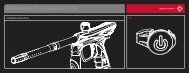
M3-A1 CIRCUIT BOARD<br />
Battery Connector<br />
Solenoid Valve Connector<br />
SW1<br />
BATT<br />
SOL<br />
EC1<br />
Power Button<br />
POWER ON<br />
SW2<br />
LED1<br />
SENSOR<br />
Micro Switch<br />
Eye Sensor<br />
Connect<br />
Press and hold until it illuminates.<br />
Release and marker is ready to fire.<br />
Fire the marker.<br />
FIRING MODE OPERATION<br />
POWER OFF<br />
Firing mode invokes programming mode at<br />
power up.<br />
Press and hold 2 seconds until board<br />
turns off. Release and marker is off.<br />
EYE CONTROL<br />
Tap to toggle eye sensor on/off.<br />
LED<br />
Green light indicates that battery level is strong.<br />
Red light indicates that the battery level is low.<br />
19
PROGRAMMING YOUR M3-A1<br />
1. POWER<br />
POWER ON<br />
● Press and hold down Button to turn on the marker with eye sensors on.<br />
● When battery voltage is lower than 7.2V, the indicator light will flash red.<br />
When battery voltage is over 7.2V then the indicator light will flash green.<br />
● When the M3-A1 eye sensors are on the indicator will blink a slow green<br />
light (1 blink/0.5 seconds). The indicator light will remain solid green when<br />
paintball is in the breech.<br />
● To turn the eye sensors off, press and release Button. When the M3-A1<br />
eye sensors are off the indicator light will blink a quick green light (1 blink/<br />
0.2 seconds).<br />
LIGHT WINDOW<br />
BUTTON<br />
POWER OFF<br />
● Press and hold down Button for 2 seconds before indicator light turns off.<br />
● The marker will shut down automatically after being idle for 20 minutes.<br />
The marker will retain the last adjusted set points whether it shutdown<br />
automatically, manually or by removing the battery.<br />
20
2. CONFIGURATION MODE<br />
SETTING OPTIONS AS BELOW<br />
Functionality<br />
Mode<br />
LED<br />
Factory<br />
Default<br />
Min / Max<br />
Rate Of Fire<br />
Red<br />
13<br />
5 / 25<br />
Firing Mode<br />
Green<br />
1<br />
1 / 5<br />
Trigger Debounce<br />
Red Flash<br />
15<br />
1 / 20<br />
Solenoid Dwell<br />
Green Flash<br />
14<br />
10 / 20<br />
ABS Dwell<br />
Yellow Flash<br />
4<br />
1 / 4<br />
21
FIRING MODE<br />
Mode<br />
Semi<br />
PSP3<br />
NXL<br />
Millennium<br />
Burst<br />
Description<br />
First 1 shot per trigger pull.<br />
Three semi shots then transitions to 3 round bursts. Returns to semi mode<br />
after 1 second of no activity.<br />
Semi for the first 3 shots, then fully automatic on the 4th shot. Resets to<br />
semi after 1 second of no activity.<br />
When triggering pull speed up to 8 BPS ramping will turn on at the 6 fire,<br />
maximum fire rate can adjust at the ROF.<br />
3 shot per trigger pull.<br />
SOLENOID DWELL<br />
This value controls the allotted time (in milliseconds) the solenoid is open. If too low, the marker will not<br />
cycle. If the value is too high, the solenoid will remain open too long therefore decreasing battery and air<br />
efficiency.<br />
ABS DWELL<br />
Adds an additional 1-3 milliseconds of dwell time to the programmed solenoid dwell setpoint on the first<br />
shot of any string of shots after a fixed 20 seconds of shooting inactivity. A value of 4 disables the ABS<br />
Dwell feature.<br />
22
RESET<br />
To reset the marker to manufacturer default settings, press and hold down the trigger then press and hold<br />
down the on/off button. Release the on/off button and hold on to the trigger for 10 seconds until yellow light<br />
appears.<br />
3. EXAMPLE SETTING FROM SEMI TO MILLENNIUM<br />
1. Turn off the marker before entering the setting mode.<br />
2. Pull and hold the trigger then press power button to turn on the marker. Release the power button then<br />
trigger, the LED will be Red which indicates the Rate of Fire setpoint.<br />
3. Pull trigger once to proceed to the next function selection mode, when the LED turns green then the<br />
functional mode will be at the firing set point. Press the POWER button once to enter the observation<br />
mode which will display the last setting. The LED will then flash the value that was previously set.<br />
● Pulling the trigger during observation mode will cycle through to the next function upon each pull.<br />
● If the original setting is at 4, the LED will flash 4 times signifying its set point.<br />
4. Follow-up to step(3), then press POWER button once (LED will blink red, green, and yellow in a second<br />
indicating access to the adjustable settings mode).<br />
5. Following steps(4), in accordance with pulling the trigger 4 times (it will set the value to 4 [Millennium<br />
Mode]). Press the power button one time to indicate the set and to leave the adjustment mode back to<br />
Step 3 observation mode. The last settings well be reflected in the blinking of the indicator light.<br />
6. The board may now be turned off, setting the mode, or cycled through to other options.<br />
23
CARE AND MAINTENANCE<br />
Routine care and maintenance for your Dangerous Power M3-A1 will ensure many years of high<br />
performance and enjoyment. When in doubt, always seek the assistance of a Dangerous Power<br />
Authorized Service Dealer, or contact Dangerous Power Customer Service.<br />
DEGASSING THE M3-A1<br />
Always be sure to completely de-gas your marker before performing maintenance or service repair.<br />
Carefully follow the instructions below in sequence to ensure that all remaining air has been removed<br />
from the entire marker.<br />
1. Twist the ASA to the “OFF” position. This disconnects the air source from the marker.<br />
2. Remove the paintball loading device and check to make sure there are no paintballs within the breech.<br />
3. Unscrew the air <strong>system</strong> from the ASA.<br />
4. Point the marker in a safe direction, and then fire 1-2 shots to remove air from the OPR. Be aware that<br />
the marker may still fire without an air <strong>system</strong> attached!<br />
5. Power OFF the marker.<br />
24
IMPORTANT NOTES BEFORE SERVICING YOUR MARKER :<br />
● DP ENGINEERS SUGGEST YOU ALWAYS USE DP-40 LUBE TO SERVICE YOUR MARKER.<br />
● DO NOT APPLY EXCESSIVE LUBRICANT.<br />
● ALWAYS INSPECT AND CLEAN YOUR MARKER AFTER EACH USE.<br />
● NEVER APPLY EXCESSIVE FORCE WHEN REMOVING OR REPLACING SCREWS. DOING SO<br />
MAY STRIP THE SCREW HEADS OR DAMAGE THREADS.<br />
● ALWAYS USE THE CORRECT SIZE AND THE APPROPRIATE TOOLS.<br />
● REFRAIN FROM SUBMERGING ENTIRE MARKER IN LIQUID. KEEP SENSITIVE ELECTRONICS<br />
SUCH AS SOLENOID AND CIRCUIT BOARD FREE FROM MOISTURE.<br />
● NEVER ALLOW SOMEONE WHO IS UNFAMILIAR WITH YOUR MARKER TO PERFORM<br />
MAINTENANCE OR REPAIR WORK. WHEN IN DOUBT, CONTACT DP ENGINEERING CUSTOMER<br />
SERVICE.<br />
25
DISASSEMBLE THE M3-A1<br />
1. Use a screwdriver to push out frame lock pin. (PIC 08)<br />
2. Remove the pin. (PIC 09)<br />
3. open up the marker body. (PIC 10)<br />
26<br />
PIC 08 PIC 09 PIC 10
BATTERY FITTING METHOD<br />
1. Open up the marker body. (Refer to page 26)<br />
2. Locate battery harness and attach 9V battery to the connector pad. Do not use force! (PIC 11)<br />
3. Place battery into available compartment in the magazine weld. (PIC 12)<br />
4. Confirm the installation is complete, reinstall body back to trigger frame. (PIC 13)<br />
PIC 11 PIC 12 PIC 13<br />
27
SOLENOID MAINTENANCE<br />
The M3-A1 solenoid is a delicate electronic component that requires minimal maintenance or service.<br />
DP Engineering does not recommend frequent cleaning of this part, or its internals.<br />
The following instructions are provided for reference and for expert airsmiths only.<br />
1. Open on the marker body. (Refer to page 26)<br />
2. Gently secure the base of the connectors and pull up to remove the plug. DO SO ONE AT A TIME.<br />
It may be helpful to use needle nose pliers. Note the location and direction of the connectors on the<br />
circuit board for reassembly. (SEE PIC 14)<br />
3. Using (5/64") allen wrench key, locate and remove both screws securing the solenoid to the marker<br />
body. (SEE PIC 15-)<br />
4. Once both screws are removed, gently lift and remove the solenoid. (SEE PIC 16)<br />
5. Place solenoid on a flat surface, with the wiring harness side facing down and solenoid disassembly<br />
screw facing up.<br />
6. Secure base of solenoid casing with an adjustable wrench (not provided). Using a slotted (flathead)<br />
screwdriver, remove screw carefully by turning it counterclockwise. Be extremely careful not to strip<br />
the screw. (SEE PIC 17)<br />
1<br />
2<br />
28<br />
PIC 14 PIC 15 PIC 16 PIC 17
6. Remove solenoid spring. (SEE PIC 18)<br />
7. With thin tweezers or needle nose pliers, carefully remove the solenoid piston by gently securing the<br />
tip and pulling it out. (SEE PIC 19)<br />
8. Carefully inspect and clean solenoid piston o-rings. Make sure the o-rings are not cracked, broken, or<br />
show signs of wear. Replace parts if necessary.<br />
9. With a cotton swab, lightly apply a small amount of DP-40 lube to the solenoid piston assembly. (SEE PIC 20)<br />
10. Replace in reverse order.<br />
Never use force when removing or reinstalling the solenoid and its sensitive<br />
Internals. Be careful not to bend, twist, or break delicate wires, as doing so<br />
may render the unit inoperative or cause it to malfunction.<br />
PIC 18 PIC 19 PIC 20<br />
29
CLEANING THE EYE-SENSOR BREAK BEAM SYSTEM<br />
1. Open on the marker body. (Refer to page 26)<br />
2. Remove the solenoid. (Refer to page 28)<br />
3. Using (5/64") allen wrench key, locate and remove both screws securing the eye-sensor break<br />
beam <strong>system</strong>. (PIC 21-)<br />
4. Remove the eye-sensor break beam <strong>system</strong>. (PIC 22)<br />
5. Using (5/64") allen wrench key, locate and remove both screws securing the eye-sensor <strong>system</strong>.<br />
(PIC 23-)<br />
6. Remove the eye-sensor <strong>system</strong>. (PIC 24)<br />
2<br />
1<br />
2<br />
1<br />
30<br />
PIC 21 PIC 22 PIC 23 PIC 24
7. With a cotton swab, gently wipe the back and front side of the eye sensor and the eye socket to<br />
remove any debris or residue. (PIC 25)<br />
8. Use (3/32") allen wrench key to remove base on both sides of the screw in order to take out spring<br />
and ball detent. (PIC 26&27)<br />
PIC 25 PIC 26 PIC 27<br />
31
9. With a cotton swab, clean the base and within the hole of dirt. (PIC 28)<br />
10. With a cotton swab, clean the spring and ball detent. (PIC 29)<br />
11. Reinstall eye sensor <strong>system</strong> in the reverse order of the removal (Be careful<br />
not to install wires in the yellow area to keep clear of the micro-switch).<br />
(PIC 30)<br />
PIC 28 PIC 29<br />
32<br />
PIC 30
REMOVING TRIGGER FROM FRAME<br />
1. Locate the two trigger adjustment screws. Use (5/64") allen key wrench to loosen and remove both<br />
screws by turning them counterclockwise. Be careful not to misplace the screws. (SEE PIC 31-)<br />
2. Locate trigger removal screw. Use (5/64") allen key wrench to loosen and remove screw by turning<br />
it counterclockwise. Carefully pull out screw. Note that the latter part of the screw is a bolt, which<br />
the trigger hinges upon. (SEE PIC 31-)<br />
3. Remove trigger assembly by lifting it up and out of M3-A1 trigger frame. (SEE PIC 32&33)<br />
Be careful not to lose the trigger return<br />
spring during maintenance.<br />
1<br />
2<br />
3<br />
PIC 31 PIC 32 PIC 33<br />
33
REMOVE THE FRAME<br />
1. Open up the marker body. (Refer to page 26)<br />
2. Use T-hex wrench key (5/32") to remove the screws. (PIC 34-&35)<br />
3. Remove the pistol grip. (PIC 36)<br />
1<br />
2<br />
34<br />
PIC 34 PIC 35 PIC 36
MAINTAINING THE DCI SYSTEM<br />
1. Open up the marker body. (Refer to page 26)<br />
2. Remove the DCI <strong>system</strong> from the body. (PIC 37)<br />
3. Unscrew the front bolt housing by twisting the front piece counter clockwise to separate from the <strong>system</strong>.<br />
(PIC 38)<br />
4. Remove bolt from bolt front. (PIC 39)<br />
5. Using (1/4") allen wrench in the Regulator set end, and using (7/32") allen wrench in the Bolt Valve end,<br />
rotate open in a counterclockwise motion. (PIC 40&41)<br />
PIC 38 PIC 40<br />
PIC 37 PIC 39 PIC 41<br />
35
6. Remove Regulator PistonRegulator Spring and Washer from Bolt Valve. (PIC 42)<br />
7. Disassemble parts down from left to right : Bolt Valve, Front Bolt, Regulator Piston, Bolt,<br />
Spring and Washer, Regulator Set. (PIC 43)<br />
8. Apply thin coating of lubricant on the bolt and bolt front O-ring parts. (PIC 44)<br />
36 PIC 42 PIC 43 PIC 44
9. Apply lubricant on the Regulator SetRegulator Piston and Bolt Valve O-ring parts. (PIC 45)<br />
10. Repeat the previous steps in reverse order for reinstallation (Be sure to properly align the velocity<br />
adjustment port, on the bolt, with the body to ensure correct instillation). (PIC 46&47)<br />
PIC 45<br />
PIC 46 PIC 47<br />
37
TROUBLESHOOTING<br />
PROBLEM<br />
M3-A1 will not<br />
turn on<br />
M3-A1 will not<br />
fire<br />
M3-A1 will not<br />
fire with sensor<br />
<strong>system</strong> on<br />
M3-A1 will not<br />
cycle completely<br />
POSSIBLE CAUSE<br />
Not activated<br />
Low battery power<br />
Battery is connected incorrectly to the<br />
PC board<br />
Low battery power<br />
Low air pressure<br />
Solenoid wiring harness may be<br />
disconnected<br />
Pressure is too low<br />
No paintball present<br />
Sensor <strong>system</strong> is unclean<br />
Broken paintball inside<br />
Ball detent is damaged<br />
Air pressure is too low<br />
Dwell time is too short<br />
Low battery power<br />
Bolt o-ring is worn<br />
Bolt O-rings lack sufficient lubricant<br />
SOLUTION<br />
Hold down operating button for more than 4<br />
seconds<br />
Replace with fresh battery<br />
Check to see if the battery cable is connected<br />
correctly to the terminal<br />
Replace with fresh battery<br />
Refill the air <strong>system</strong><br />
Open grip and press down the harness to ensure<br />
it is properly secured.<br />
Adjust pressure without paintball present<br />
Turn on the loader<br />
Remove and clean sensor eye<br />
Refer to bolt maintenance<br />
Change ball detent<br />
Adjust the operating pressure to 150 to 200 psi<br />
See ”dwell adjust <strong>system</strong>”<br />
Change battery<br />
Change o-ring<br />
Lubricate the o-ring with DP-40 lubricant<br />
38
PROBLEM<br />
Air leaking from<br />
barrel area<br />
<strong>Paint</strong>ball breaking<br />
out of the barrel<br />
<strong>Paint</strong>ball chopping<br />
internally<br />
POSSIBLE CAUSE<br />
Bolt Valve o-ring is worn<br />
Internal o-ring is worn or damaged<br />
Barrel size does not match paintball’s<br />
Ball detent is worn<br />
Sensor <strong>system</strong> is not on<br />
Low battery power<br />
Change o-ring<br />
Change o-ring<br />
SOLUTION<br />
The stock barrel size is 0.690, change if<br />
necessary<br />
Change ball detent<br />
Switch it to ON<br />
Replace with fresh battery<br />
39
STATEMENT OF LIABILITY<br />
The manufacturer assumes no responsibility for this product’s safe operation upon sale or distribution.<br />
PROPERTY DAMAGE, BODILIY INJURY, OR DEATH could occur due to misuse, abuse, or failure to<br />
follow the manufacturer’s instructions stated in this manual. The manufacturer will assume no responsibility<br />
for physical injury or property damage resulting from the use of this marker. The information in this document<br />
is subject to change without prior notice. The manufacturer assumes no responsibility for any errors that may<br />
appear in this document.<br />
DISCLAIMER<br />
Notice is hereby given that this owner’s manual is part of the article owned in whole by the manufacturer,<br />
know as indicated by this disclaimer and all illustrations within the manual. All rights for manufacturing and<br />
reproducing of such articles or any part thereof are reserved by the manufacturer. Neither said article nor<br />
any part thereof may be manufactured or reproduced in any way except by the written authorization of the<br />
manufacturer. All proprietary truths and information are the sole property of the manufacturer.<br />
40
LIMITED WARRANTY<br />
DANGEROUS POWER warrants this M3-A1 paintball marker, to the initial retail purchaser, to be free from<br />
defect in original materials and/or workmanship for twelve( 12 ) months from the original date of purchase, with<br />
the following exceptions<br />
1. Disposable parts ( batteries, o-rings, seals, micro switch, air pressure hose,rubber and/or plastic material<br />
parts,etc. ) are not included in this limited lifetime warranty.<br />
2. Electronic parts on this marker are fully warranted for 30 days from the original date of purchase.<br />
3. Bolt and striker <strong>system</strong>s of this marker are fully warranted for 6 months from the original date of purchase.<br />
4. Surface damages ( scratches and nicks ) or operation failure due to accident, neglect, modification, normal<br />
wear, operator error, maintenance by anyone other than an authorized dealer or agent, misuse, improper<br />
disassembly and reassembly, are expressly not covered under this warranty.<br />
PURCHASER IS RESPONSIBLE FOR ALL RENDERED SERVICES NOT COVERED UNDER<br />
THIS LIMITED WARRANTY, INCLUDING ANY APPLICABLE SHIPPING COSTS, LABOR AND/<br />
OR INSTALLATION.<br />
DANGEROUS POWER reserves the right to determine the legitimacy of claimed defective original parts and<br />
their eligibility for coverage under the terms of this warranty. DANGEROUS POWER, its authorized dealers,<br />
affiliates, and/or agents,will not be held liable under this warranty, state, federal, or common law for any product<br />
failure, personal injury, or property damage resulting from improper use and/or alteration of this product. Any<br />
attempt to alter the trigger assembly will instantly void your warranty and may result in serious injury. Any<br />
attempt to alter basic marker parts without prior written consent from the manufacturer will result in automatic<br />
default of all expressed warranties.<br />
This limited warranty is non-transferable and is valid only upon presentation of a completed warranty registration<br />
card and original proof of purchase. There are no other warranties or guarantees, expressed or implied, made by<br />
the manufacturer on this paintball marker.<br />
PAINTBALL MARKERS ARE NON-REFUNDABLE AND ARE NOT SUBJECT TO EXCHANGE<br />
FROM MANUFACTURER.<br />
41
90<br />
PARTS DIAGRAM<br />
59<br />
59<br />
16<br />
89<br />
88<br />
87<br />
85<br />
97<br />
17<br />
2<br />
13<br />
15<br />
4<br />
14<br />
86<br />
1<br />
6<br />
37<br />
38<br />
7<br />
5<br />
103<br />
39<br />
42<br />
82<br />
54<br />
53<br />
18
57<br />
66<br />
56<br />
83<br />
55<br />
77<br />
105<br />
83<br />
106<br />
43<br />
58<br />
84<br />
81<br />
107<br />
60<br />
108<br />
61<br />
62<br />
68<br />
67<br />
78<br />
43
NO.6<br />
9<br />
2<br />
20<br />
NO.18<br />
10<br />
11<br />
21<br />
8<br />
12<br />
19<br />
26<br />
22<br />
24<br />
25<br />
7<br />
11<br />
10<br />
23<br />
9<br />
27<br />
22<br />
28<br />
29<br />
30<br />
31<br />
32<br />
19<br />
3<br />
31<br />
19<br />
36<br />
19<br />
104<br />
33<br />
34<br />
35<br />
44
NO.38<br />
37<br />
40 41<br />
43<br />
65<br />
63<br />
43<br />
44<br />
46<br />
47<br />
48<br />
50<br />
42<br />
51<br />
49<br />
45<br />
69<br />
66<br />
64<br />
NO.68<br />
NO.62<br />
NO.78<br />
80<br />
52<br />
NO.98<br />
99<br />
100<br />
73<br />
70<br />
101<br />
72<br />
71<br />
98<br />
102<br />
76<br />
79<br />
75<br />
74 76<br />
17<br />
45
96<br />
94<br />
96<br />
95<br />
92<br />
93<br />
NO.90<br />
95<br />
92<br />
96<br />
96<br />
96<br />
92<br />
91<br />
87<br />
46
PARTS LIST<br />
No Item Number<br />
Qty Note<br />
1 20-B01305-201-PM100B 1<br />
2 20-F01730-000-PTHR7A 2 Ø17.17xØ1.78<br />
3 20-F01530-000-PFUS0A 1 Ø7.65xØ1.78<br />
4 20-W11090-000-PM100B 2 M3xP0.5-4L<br />
5 20-W11100-000-PM100B 3 #5-40-1/8”L<br />
6 20-A06270-301-PM100B 1<br />
7 20-W11020-000-PSPI0B 4 #3-56-4L<br />
8 20-W23720-000-PM100B 1<br />
9 20-W11082-000-PM100B 2 #10-32UNF-1/8”L<br />
10 20-G10360-000-PM100B 2<br />
11 20-E01190-000-PM100B 2<br />
12 20-B30983-301-PM100B 1<br />
13 20-0209T104-00-PM100B 1<br />
14 20-MA-30-03-PM100B 1<br />
15 20-0209D106-00-PM100B 1<br />
16 20-W11120-000-PM100B 1 #8-32-5/16”L<br />
17 20-W11130-000-PM100B 5 #5-40-1/4”L<br />
18 20-A40200-301-PM100B 1<br />
19 20-F01740-000-PTHR7A 6 Ø25.12xØ1.78<br />
20 20-B10452-301-PM100B 1<br />
21 20-B10472-301-PM100B 1<br />
22 20-F01720-000-PTHR7A 2 Ø13.8xØ1.9<br />
23 20-F01750-000-PTHR7A 1 Ø15.8xØ1.9<br />
24 20-F05060-000-PM100B 1 White<br />
25 20-B10442-301-PM100B 1<br />
26 20-F01510-000-PFUS0A 1 Ø14xØ1.78<br />
27 20-B10482-301-PM100B 1<br />
28 20-G10332-000-PFX00B 1<br />
29 20-H01060-000-PFX00B 1<br />
30 20-B20262-307-PFX00B 1<br />
31 20-F01520-000-PFUS0A 2 Ø5.29xØ1.78<br />
32 20-H03233-000-PG400B 1<br />
33 20-W01050-000-PXMT0A 1 Ø1/4”<br />
34 20-H01040-000-PG400B 1<br />
35 20-B10462-301-PM100B 1<br />
36 20-F01910-000-PM100B 1 Ø18.72xØ2.62<br />
No Item Number<br />
Qty Note<br />
37 20-F01780-000-PG300B 3 Ø2xØ1<br />
38 20-A06260-301-PM100B 1<br />
39 20-W11060-000-PFX00B 2 #3-56UNF-10L<br />
40 20-C20060-104-PFX00B 1<br />
41 20-F01850-000-PFX00B 1 Ø5xØ1<br />
42 20-A06230-307-PFX00B 1<br />
43 20-W10780-000-PFUS0A 3 #3-56UNF-19.8L<br />
44 20-C01052-104-PFX00B 1<br />
45 20-F01860-000-PFX00B 1 Ø5.5xØ1<br />
46 20-C20053-104-PTHR7A 1<br />
47 20-G10340-000-PFX00B 1<br />
48 20-B20313-301-PM100B 1<br />
49 20-H05480-000-PTHR7A 1<br />
50 20-F01700-000-PFUS0A 4 Ø2xØ1<br />
51 20-G10220-000-PFUS0A 1<br />
52 20-H03112-000-PFUS0A 1<br />
53 20-W23710-000-PM100B 1<br />
54 20-W10840-000-PFUS0A 3 #3-56UNF-5/32”L<br />
55 20-B05345-401-PM100B 1<br />
56 20-G10250-000-PFUS0A 1<br />
57 20-B30975-201-PM100B 1<br />
58 20-W11014-000-PFUS8A 2 #8-32UNC<br />
59 20-W10730-000-PFUS0A 2 #8-32UNC-5/16”L<br />
60 20-E01222-000-PM100B 1<br />
61 20-E01232-000-PM100B 1<br />
62 20-A60330-401-PM100B 1<br />
63 20-B30995-201-PM100B 1<br />
64 20-H05700-000-PM100B 1<br />
65 20-G10370-000-PM100B 1<br />
66 20-W10952-000-PTHR7A 2 #8-32-6.35L<br />
67 20-LZSP0008-00-PM100B 1<br />
68 20-A20340-401-PM100B 1<br />
69 20-F01930-000-PM100B 1 Ø4.47xØ1.78<br />
70 20-B05335-201-PM100B 1<br />
71 20-F01900-000-PE100B 1 Ø2.9xØ1.78<br />
72 20-D05230-000-PE100B 1<br />
No Item Number<br />
Qty Note<br />
73 20-H05670-000-PM100B 1<br />
74 20-H01070-000-PE100B 1<br />
75 20-B20304-201-PM100B 1<br />
76 20-X46450-000-PM100B 2<br />
77 20-H03170-000-PREV0B 2 #1/4”-28UNF-12.7L<br />
78 20-A30072-201-PM100B 1<br />
79 20-B31014-401-PM100B 1<br />
80 20-B31024-401-PM100B 1<br />
81 20-X30280-000-PM100B 1<br />
82 20-W23760-000-PM100B 1<br />
83 20-MA-22-00-PM100B 1<br />
84 20-LDM10008-00-PM100B 1<br />
85 20-MA-21-00-PM100B 1<br />
86 20-MA-25-00-PM100B 1<br />
87 20-MA-100-00-PM100B 1<br />
88 20-F01820-000-PSPE0B 1 Ø12.42xØ1.78<br />
89 20-B16332-401-PM100B 1<br />
90 20-A60340-201-PM100B 1<br />
91 20-MA-101-00-PM100B 1<br />
92 20-MA-102-00-PM100B 1<br />
93 20-MA-98-00-PM100B 1<br />
94 20-MA-97-03-PM100B 1<br />
95 20-MA-95-00-PM100B 1<br />
96 20-MA-94-00-PM100B 1<br />
97 20-A60320-201-PM100B 1<br />
98 20-B25744-201-PM100B 1<br />
99 20-H05560-000-PFUS0A 1<br />
100 20-B31094-201-PM100B 1<br />
101 20-C25030-104-PG300B 1<br />
102 20-H03150-000-PG300B 1<br />
103 20-F01920-000-PM100B 1 Ø7.65xØ1.78<br />
104 20-W10870-000-PG400B 1 1/4”-28UNF-6.35L<br />
105 20-MA-16-00-PM100B 1<br />
106 20-MA-27-03-PM100B 1<br />
107 20-F10240-000-PM100B 1<br />
108 20-G10390-000-PM100B 1<br />
47
Name<br />
Product Registration Card<br />
Fill out all of the information below completely. To activate your warranty.visit www.dangerouspower.com<br />
and click on “SUPPORT” to register your product within 7 days of purchase. Keep this card and your receipt<br />
or proof of purchase - you will be asked to include both when sending in your product for warranty service.<br />
Address<br />
Apt/Suite#<br />
City Sate Province<br />
Zip/Postal Code County Country<br />
Phone ( ) Fax ( )<br />
Email<br />
Name of Product Purchased<br />
Date of Purchase (dd/mm/yy) Product Color<br />
Place of Purchase<br />
Product Serial Number (if applicable)<br />
I guarantee all of the information completed above to be true and correct to the best of my knowledge.<br />
Signature<br />
Date<br />
Visit www.dangerouspower.com for more information on how to claim warranty.
Copyright © Dangerous power. The “Dangerous Power” logo and “dp”<br />
logo are registered trademarks. All rights reserved.