Create successful ePaper yourself
Turn your PDF publications into a flip-book with our unique Google optimized e-Paper software.
Customer Service:<br />
PBX Ballistix Lab LLC<br />
www.pbxlab.com<br />
126 Woodland Rd.<br />
1-800-393-4196 Madison, NJ 07940<br />
A. Contents of Package<br />
▪Manual<br />
▪<strong>mQ</strong>-<strong>Valve</strong>, consisting of:<br />
<strong>mQ</strong>-<strong>Valve</strong> <strong>Instructions</strong><br />
Gui<strong>de</strong> Rod Spacer Pilot Poppet <strong>Valve</strong> Body<br />
B. Prepare Your Marker for Installation<br />
You will need to disassemble certain parts of your Autococker before you install the <strong>mQ</strong>-<strong>Valve</strong>. This section<br />
will walk you thru each step. DE-GAS YOUR MARKER AND REMOVE THE AIR SYSTEM BEFORE<br />
BEGINNING THE INSTALLATION.<br />
STEP 1. REMOVE THE GRIP FRAME<br />
● Consult your e-grip’s product manual for instructions.<br />
● Remove the sear / solenoid and associated hardware from your e-grip. These parts are not necessary with<br />
the <strong>mQ</strong>-<strong>Valve</strong>.<br />
STEP 2. REMOVE THE HAMMER AND MAIN VALVE<br />
● Remove the following parts from your marker: valve, valve spring, jam nut, valve setscrew, and hammer<br />
assembly. You will need to remove your backblock and bolt for this process. A special tool is nee<strong>de</strong>d to<br />
remove the valve. Save the IVG, valve setscrew, and cocking rod for reassembly. Consult your marker’s<br />
manual for additional help.<br />
C. <strong>mQ</strong>-<strong>Valve</strong> Installation<br />
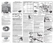
STEP 1. INSERT VALVE BODY<br />
● Push poppet back and forth in the valve<br />
body to ensure it is not stuck.<br />
● Insert the <strong>Valve</strong> body with the Poppet<br />
and Spring in place as shown in the<br />
picture. Make sure the o-ring at the rear of<br />
the valve body and spring stay in place<br />
after dropping into the body.<br />
● Align the hole of the valve body with<br />
the hole in the gun body<br />
STEP 2. INSERT PILOT<br />
● Feed the wire of the solenoid thru the body and out<br />
the slot where the sear lug would normally be.<br />
● Gently insert the solenoid into the marker body while<br />
pulling the remain<strong>de</strong>r of the wire thru the slot.<br />
● Align the wire and the slot in the solenoid spacer<br />
with the slot in the body.
STEP 3. INSERT GUIDE ROD SPACER<br />
● Insert the gui<strong>de</strong> rod spacer with the hollow end toward the IVG.<br />
STEP 4. TIGHTEN IVG<br />
● Use an allen key to keep<br />
the solenoid spacer from<br />
rotating while threading<br />
IVG back into the marker.<br />
The IVG needs to be as<br />
tight as the original valve<br />
jam nut in or<strong>de</strong>r to seal the<br />
front of the <strong>mQ</strong>-<strong>Valve</strong>. IF<br />
THE PILOT ROTATES,<br />
THE WIRES COULD BE SHEARED OFF!<br />
STEP 5. INSPECT VALVE<br />
● The valve should appear as shown in the picture. Be sure the hole in<br />
the valve body is aligned with the hole in the gun and that the wires<br />
are not pinched.<br />
D. Reassemble Your Marker<br />
STEP 1. REASSEMBLE BODY<br />
● Reinstall the valve setscrew flush with the bottom of the body. Do not thread in more than necessary.<br />
● Reinstall bolt and backblock<br />
● Thread your cocking rod thru the back block and into the rod gui<strong>de</strong>. This is only to stabilize your back<br />
block so it does not rotate and snap your pump arm. The cocking rod may be shortened if <strong>de</strong>sired.<br />
STEP 2. RE-ASSEMBLE THE GRIP FRAME<br />
● Consult your e-grip’s product manual for instructions<br />
● Thread the wires through the opening left by the sear components. Avoid pinching the wires when installing<br />
the grip frame. Plug the <strong>mQ</strong>-<strong>Valve</strong> solenoid into the board where the sear tripper solenoid used to be.<br />
E. Tuning Your Marker<br />
STEP 1. MQ-VALVE<br />
● Set the solenoid dwell time to 4 ms (this is controlled by the sear tripper solenoid dwell time, consult your<br />
grip frame manual for that procedure). Race frame users will need around 7ms due to their lower voltage.<br />
● Set your marker’s pressure to between 250 and 320 psi. You will want to run at as high a pressure as<br />
possible. If you over pressurize the valve a pressure release seal will start to hiss. Lower the pressure and the<br />
seal will re-seat.<br />
● Chronograph your gun to the <strong>de</strong>sired speed by adjusting the input pressure to your marker (via your main<br />
regulator). If your <strong>de</strong>sired velocity is not reached by increasing your pressure, ie, the relief valve starts<br />
hissing, then lower the pressure a little bit and raise the solenoid dwell by 1 ms.<br />
STEP 2. FIRE RATE<br />
● With no hammer and spring to re-cock, the system should open the bolt faster, allowing a ball to drop in<br />
faster. It will automatically re-adjust if you are using the eye. If not, you can lower your “bolt open time”.<br />
● Due to the <strong>mQ</strong>-<strong>Valve</strong>’s fast response time, the time allowed for the bolt to close should be increased<br />
slightly. The time between activating the valve and activating the cocking solenoid should be <strong>de</strong>creased as<br />
well.<br />
● You can re-adjust the cocking pressure of you marker to your <strong>de</strong>sired settings.<br />
See our website at www.pbxlab.com for additional help.<br />
© 2005 PBX Ballistix Lab LLC | rev 1.2