You also want an ePaper? Increase the reach of your titles
YUMPU automatically turns print PDFs into web optimized ePapers that Google loves.
INSTRUCTION MANUAL<br />
Suction Unit for Sample <strong>Volume</strong> Flow Rates<br />
ISOK 4 - F<br />
Isokinetic Sampling in Gas Streams<br />
According to VDI 2066 and EN 13284-1<br />
<strong>Paul</strong> <strong>Gothe</strong> <strong>GmbH</strong><br />
Seit 1924<br />
______________________________________________________________________________________<br />
SVEN LECKEL <strong>GmbH</strong><br />
Leberstraße 63, D-10829 Berlin<br />
<strong>Paul</strong> <strong>Gothe</strong> <strong>GmbH</strong><br />
Wittener Straße 82, D-44789 Bochum<br />
Telephone +49 (0)30 – 78 95 50 11 Telephone +49 (0)234 – 33 51 80<br />
Fax +49 (0)30 – 78 95 50 12 Fax +49 (0)234 – 30 82 17<br />
Internet http://www.leckel.de Internet www.paulgothe.de<br />
E-Mail info@leckel.de E-Mail info@paulgothe.de
Contents<br />
1. Technical data 2<br />
2. Principle 3<br />
3. Mode of function 3<br />
3.1 Modes of operation 3<br />
3.2 Application 4<br />
3.3 Sampling 5<br />
3.4 Laboratory test 7<br />
3.5 Report 8<br />
3.6 Downloading of data by PC 9<br />
4. Operating 10<br />
4.1 Menu-guided operation 10<br />
4.2 Selecting a language 23<br />
5. Safety advice 25<br />
6. Guarantee 25<br />
7. Generally Notes 25<br />
This documentation contains trade secrets and confidential information<br />
proprietary to LECKEL <strong>GmbH</strong>. Therefore, this documentation and any<br />
information contained therein may not be used, duplicated or disclosed to<br />
anyone, in whole or in part, other than as with the permission of<br />
LECKEL <strong>GmbH</strong>.<br />
Ed. 46/07<br />
ISOK4-engl. 1
1. Technical data<br />
<strong>Volume</strong> measurement:<br />
<strong>Volume</strong> <strong>flow</strong> <strong>rate</strong>:<br />
Modes of operation:<br />
Orifice plate (abs. 400 .. 1070 mbar)<br />
Orifice plate<br />
Orifice plate 1: circa 0.9 – 4 m³/h<br />
Orifice plate 2: circa 0.5 – 1.5 m³/h<br />
(related to the conditions at the<br />
orifice plate)<br />
Isokinetic sampling with gas velocity<br />
measuring device<br />
Isokinetic sampling with zero<br />
pressure tube<br />
Constant sample volume <strong>flow</strong> <strong>rate</strong><br />
Additional volume <strong>flow</strong> <strong>rate</strong><br />
Number of measuring points: 1 - 35<br />
Sampling duration:<br />
Nozzle diameter:<br />
1 – 1500 min per measuring point<br />
1 – 40 mm<br />
Additional volume <strong>flow</strong> <strong>rate</strong>: -2 – 2 m³/h<br />
(standard conditions: 0 °C and<br />
1013 mbar respectively 760 mm Hg)<br />
Power supply:<br />
Dimensions:<br />
Weight:<br />
230 V, 50/60 Hz<br />
Width 360 mm<br />
Height 440 mm<br />
Depth 360 mm<br />
approx. 16 kg<br />
Operating condition: 0 – 50°C<br />
Subject to alterations<br />
ISOK4-engl. 2
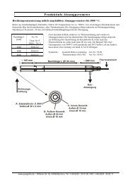
2. Principle<br />
The suction unit for sample volume <strong>flow</strong> <strong>rate</strong>s ISOK4 serves the<br />
isokinetic sampling in gas streams.<br />
The sample volume <strong>flow</strong> <strong>rate</strong> is sucked through the entry nozzle (with a<br />
filter following downstream) from the gas stream by a frequency<br />
controlled gas-tight rotary vane vacuum pump. The sample volume <strong>flow</strong><br />
<strong>rate</strong> is measured between the filter and the pump by means of an orifice<br />
plate and controlled by a frequency converter. If the static pressure of the<br />
orifice is below 400 mbar, the pump must be installed in front of the<br />
ISOK.<br />
The orifice plate can be calib<strong>rate</strong>d and checked in the laboratory or<br />
at the measuring site, e.g. by means of a rotameter connected to the<br />
entry of the orifice plate’s housing.<br />
3. Mode of function<br />
3.1 Modes of operation<br />
The unit is designed for the following modes of operation:<br />
1. Isokinetic sampling with gas velocity measuring device<br />
For this mode of operation, the velocity of the gas stream must be<br />
continuously measured by means of a gas velocity measuring<br />
device (e.g. Brandtl or Pitot tube). The sample volume <strong>flow</strong> <strong>rate</strong><br />
is automatically controlled in such a way that the entry nozzle<br />
always sucks off the sample volume <strong>flow</strong> <strong>rate</strong> over-isokinetical<br />
by about 5 %. Hence, the actual sample volume <strong>flow</strong> <strong>rate</strong> is in the<br />
middle of the range from – 5 % up to + 15 % deviation from the<br />
isokinetic sampling as prescribed in the EN 13284-1 for valid<br />
sampling in gas streams.<br />
2. Isokinetic sampling with zero pressure tube<br />
In this mode of operation, the sample volume <strong>flow</strong> <strong>rate</strong> is<br />
controlled in such a way that the pressure drop measured by the<br />
zero pressure tube is always equal to zero.<br />
ISOK4-engl. 3
3. Sampling with constant sample volume <strong>flow</strong> <strong>rate</strong><br />
In this mode of operation, the pre-selected sample volume <strong>flow</strong><br />
<strong>rate</strong> is kept constant during sampling.<br />
4. Additional volume <strong>flow</strong> <strong>rate</strong><br />
Furthermore, the sampling train can be ope<strong>rate</strong>d with an<br />
additional volume <strong>flow</strong> <strong>rate</strong> (negative and positive). This<br />
additional volume <strong>flow</strong> <strong>rate</strong> is to be branched off in front of the<br />
unit’s orifice plate and to be maintained constant by a sepa<strong>rate</strong><br />
pump (see chapter 3.3 Sampling). When entering “ + “ , a part of<br />
the sample volume <strong>flow</strong> will be taken of, when entering “ - “ a<br />
<strong>flow</strong> will be added. For the calculation of the total sample<br />
volume <strong>flow</strong> <strong>rate</strong> the additional volume <strong>flow</strong> <strong>rate</strong> is taken into<br />
consideration as follows:<br />
Flow <strong>rate</strong> through orifice plate (controlled) +/- additional<br />
volume <strong>flow</strong> <strong>rate</strong> (constant) = total sample volume <strong>flow</strong> <strong>rate</strong>.<br />
Furthermore, the unit can be also ope<strong>rate</strong>d with a fixed gas<br />
temperature and a fixed static pressure of the gas, if these<br />
parameters are not measured in the gas stream during sampling.<br />
These parameters must be entered into the system prior to<br />
sampling (see chapter 3.3 Sampling).<br />
3.2 Application<br />
The unit has to be set up rainproof at the measuring site. The unit<br />
can be also set up on the legs mounted at its back. This way, the<br />
display can be read from above without difficulty.<br />
When using the unit, attention must be paid that all hoses and<br />
electrical lines are correctly connected (orifice plate, gas<br />
velocity measuring device, zero pressure tube, sensor for the<br />
temperature of the gas stream, motor of the bypass control<br />
valve).<br />
The unit is designed for volume <strong>flow</strong> <strong>rate</strong>s passing the orifice plate<br />
from about 0.4 up to 4 m³/h. These <strong>flow</strong> <strong>rate</strong>s are related to the<br />
conditions at the orifice plate (temperature and pressure). You have<br />
to pay attention that the sample volume <strong>flow</strong> <strong>rate</strong> sucked up directly<br />
from the gas stream can be considerably higher than the volume<br />
<strong>flow</strong> <strong>rate</strong> passing the orifice plate, e.g. due to the high temperature<br />
of the gas stream and/or a high additional volume <strong>flow</strong> <strong>rate</strong>.<br />
In order to cover the complete range from 0.4 up to 4 m³/h two<br />
orifice plates with bores of different sizes are needed. These orifice<br />
ISOK4-engl. 4
plates are to be put in the housing of the orifice plate mounted at the<br />
unit’s back. For that purpose, the left part of the housing (viewed<br />
from the back of the unit) is to be screwed off and the appropriate<br />
orifice plate is to be put in with the expand of the bore facing the<br />
back.<br />
- Orifice plate No. 1 (big bore)<br />
volume <strong>flow</strong> <strong>rate</strong> about 0.9 – 4 m³/h<br />
- Orifice plate No. 2 (small bore)<br />
volume <strong>flow</strong> <strong>rate</strong> about 0.5 – 1.5 m³/h<br />
Orifice plates for other ranges can not use.<br />
It is important for the correct operation of the unit to use the<br />
appropriate orifice plate for the wanted sample volume <strong>flow</strong><br />
<strong>rate</strong> and to enter the number of the inserted orifice plate into<br />
the system as described under the menu feature<br />
4) SAMPLING (see chapter 4.1 Menu-guided operation).<br />
Furthermore, the sample volume <strong>flow</strong> <strong>rate</strong> is determined by the<br />
entry nozzle’s diameter. The diameter of the nozzle is also to be<br />
entered into the system as described under menu feature<br />
4) SAMPLING <br />
If the pressure drop across the orifice plate of 90 mbar (67.5 mm<br />
Hg) is exceeded or a pressure drop of about 0 mbar is reached or the<br />
static pressure in front of the orifice falls below 400 mbar (300 mm<br />
Hg), the unit is out of its controlling range. In this case the display<br />
shows crosses (xxx) for the sample volume <strong>flow</strong> <strong>rate</strong>.<br />
It is recommended to switch on the unit by means of the red main<br />
power switch about 20 minutes before operation in order to warm<br />
up the electronics.<br />
3.3 Sampling<br />
By means of the potentiometer (adjusting knob under the red main<br />
power switch) the parameters measured in the gas stream can be<br />
damped by averaging these values. It is recommended to turn the<br />
potentiometer completely to the right (maximum damping).<br />
Intermediate positions should be tested at the site.<br />
For sampling the following parameters are to be entered into the<br />
system (see chapter 4.1 Menu-guided operation):<br />
ISOK4-engl. 5
Menu feature 3) STACK VALUES <br />
- Standard density of the gas in kg/m³<br />
related to standard conditions<br />
(0 °C and 1013 mbar resp. 760 mm Hg)<br />
- Humidity of the gas in kg/m³<br />
- Fixed static pressure of the gas in mbar (if wanted)<br />
- Fixed temperature of the gas in °C (if wanted)<br />
Menu feature 4) SAMPLING <br />
- Orifice plate no. 1 or no. 2<br />
- Number of measuring points<br />
- Sampling duration in min<br />
- Nozzle diameter in mm<br />
- Factor for velocity measuring device<br />
(isokinetic sampling)<br />
- Additional volume <strong>flow</strong> <strong>rate</strong> in m³/h<br />
related to standard conditions<br />
(0 °C and 1013 mbar resp. 760 mm Hg)<br />
Menu feature 5) CONTROL <br />
- Isokinetic sampling with gas velocity measuring device<br />
- Isokinetic sampling with zero pressure tube<br />
- Sampling with constant sample volume <strong>flow</strong> <strong>rate</strong><br />
Menu feature 6) SET CLOCK <br />
- Current time (system time)<br />
- Current date<br />
(if not already entered into the system)<br />
If necessary, the orifice plates and the sensors are to be calib<strong>rate</strong>d<br />
according to the following menu features:<br />
7) CALIBRATING ORIFICE PLATE <br />
and<br />
8) CALIBRATING SENSORS <br />
These calibrations can be also done e.g. in the laboratory (see<br />
chapter 3.4 Laboratory test).<br />
The course of sampling is comprehensively described under menu<br />
feature<br />
1) START <br />
ISOK4-engl. 6
The entered parameters are stored in the unit’s memory and are<br />
preserved also after switching off the unit.<br />
In case of changing the measuring task other related parameters<br />
have to be entered under the menu features mentioned above<br />
prior to starting the sampling process according to the menu<br />
feature<br />
START <br />
The sample volume <strong>flow</strong> <strong>rate</strong> sucked up from the gas stream is<br />
shown on the display and recorded in m³/h (related to the conditions<br />
in the gas stream). All further measuring data for each measuring<br />
point are recorded as well. The additional volume <strong>flow</strong> <strong>rate</strong> preselected<br />
in terms of m³/h related to standard conditions is also<br />
converted to m³/h related to the operating conditions in the gas<br />
stream and is taken into consideration in these units for the<br />
calculation of the total sample volume <strong>flow</strong> <strong>rate</strong>.<br />
Every measurement can be stopped by pressing down the grey<br />
cursor key for a while.<br />
3.4 Laboratory test<br />
In order to test the unit with connected gas velocity measuring<br />
device or zero pressure tube in the laboratory, a small <strong>flow</strong> channel<br />
consisting of a fan blower (adjustable by the voltage supply) with a<br />
tubing at its exhaust is needed. Both probes can be placed upstream<br />
in this tubing.<br />
For the laboratory test, the corresponding parameters are also to be<br />
pre-selected, as described under chapter 3.3 Sampling. Instead of<br />
the standard density of the gas the standard density of the air (1.293<br />
kg/m³) and for the humidity the value 0.00 kg/m³ is to be entered.<br />
When using the orifice plate no. 1 (big bore), it is recommended to<br />
pre-select a big nozzle diameter, and for the orifice plate no. 2 (small<br />
bore) a small nozzle diameter should be pre-selected.<br />
After pre-selecting the menu features<br />
7) CALIBRATING ORIFICE PLATE <br />
and<br />
8) CALIBRATING SENSORS <br />
all necessary calibrations can be done.<br />
ISOK4-engl. 7
3.5 Report<br />
After finishing the samplings, all measured parameters and results<br />
can be printed respectively stored in a Memory Stick. All<br />
parameters and results are internally stored and saved against power<br />
break down.<br />
For printing the results please proceed as follows:<br />
1. Connect the serial interface RS232 of the unit (below the display)<br />
with the printer by means of the printer cable.<br />
Please note: Remove cable during the measurements,<br />
as otherwise data can be falsified.<br />
2. Go to menu feature 10) REPORT by using the white keys<br />
(see chapter 4.1 Menu-guided operation).<br />
3. The display shows:<br />
Line 1: REPORT<br />
Line 2: PRINT? NO <br />
By using the upper white key<br />
YES <br />
can be pre-selected.<br />
After pressing the grey key the measured parameters and results<br />
will be printed:<br />
Section 1: Ident.No. of the unit<br />
Date<br />
Time<br />
Section 2: Mode of operation<br />
Further e.g.:<br />
Pre-selected <strong>flow</strong> <strong>rate</strong><br />
Number of measuring points<br />
Gas density<br />
Gas humidity<br />
etc.<br />
Section 3: Mean values during sampling, e.g.:<br />
Damping<br />
Temperature at the gas meter<br />
(additional volume <strong>flow</strong> <strong>rate</strong>)<br />
Sample volume <strong>flow</strong> <strong>rate</strong><br />
ISOK4-engl. 8
Gas temperature<br />
Gas pressure<br />
etc.<br />
For storing the data in a Memory Stick previously stuck in the<br />
lower connector please proceed as follows:<br />
Please confirm<br />
PRINT? NO (see item 3/page 8)<br />
by pressing the grey key. The display shows:<br />
Line 1: REPORT<br />
Line 2: STICK? NO <br />
By pressing the upper white key<br />
YES <br />
can be again pre-selected.<br />
After that the display shows:<br />
Line 1: REPORT<br />
Line 2: PLEASE WAIT X %<br />
The information behind PLEASE WAIT shows the percentage of<br />
the data already taken over of the Memory Stick.<br />
After PLEASE WAIT is not shown in the display anymore the<br />
stick can be removed and a new stick can be stuck in. The stored<br />
data can be downloaded from the stick in a PC via a Docking<br />
Station and the attached special software ISOKVIEW.<br />
Afterwards the data can be imported into an Excel table.<br />
3.6 Downloading of data by PC<br />
Instead of a printer also a PC or laptop can be connected to the<br />
unit’s serial interface. By means of the special software<br />
ISOKVIEW all data can be downloaded in the computer. This<br />
communication is only possible in the main menu.<br />
Please note: Remove the cable during the measurements,<br />
as otherwise data can be falsified.<br />
ISOK4-engl. 9
4. Operation<br />
4.1 Menu-guided operation<br />
The menu operation is self-explanatory.<br />
Switching on: Press the red main power switch.<br />
Display shows:<br />
After that:<br />
ISOK 4 SAMPLER<br />
1) START <br />
2) VACUUM CHECK<br />
Following menu features<br />
can be selected:<br />
upper white cursor key<br />
3) STACK VALUES<br />
4) SAMPLING<br />
5) CONTROL<br />
6) SET CLOCK<br />
7) CAL. ORIFICE<br />
8) CAL. SENSORS<br />
9) INFORMATION<br />
10) REPORT<br />
menu forward<br />
lower white cursor key<br />
menu backward<br />
When using the white cursor keys the following principle applies:<br />
Press down the keys: Display will continuously advance: first<br />
slowly, then rapidly.<br />
The menu feature currently selected is marked by an arrow <br />
1) START <br />
Press the grey key.<br />
Display Line 1:<br />
Line 2:<br />
MEMORY RESET?<br />
NO <br />
If the stored data of the previous<br />
measurements shall not be cancelled,<br />
e.g. when in transition of a sampling<br />
from one cross-section measurement to<br />
another, the grey key has to be pressed<br />
again.<br />
If the stored data of the previous<br />
measurements shall be cancelled, the<br />
upper white key is to be pressed.<br />
ISOK4-engl. 10
Line 2:<br />
YES <br />
After that, press the grey key.<br />
Display Line 1:<br />
Line 2:<br />
Then:<br />
Display Line 1:<br />
Line 2:<br />
MEMORY RESET?<br />
PLEASE WAIT<br />
MOVE PROBE<br />
ACKNOWLEDGEMENT<br />
Now press the grey key again.<br />
Display Line 1:<br />
Line 2:<br />
SELECT MEASURE<br />
01 <br />
By pressing the white keys the preselected<br />
measuring points or STOP of<br />
the measurement can be set.<br />
If the previously set operating parameters shall not be changed<br />
any- more, the unit can be put into operation by pressing the<br />
grey key.<br />
When the unit is running, the following parameters are displayed<br />
depending on the mode of operation:<br />
Isokinetic sampling:<br />
Display Line 1:<br />
Line 2:<br />
Velocity of the gas stream vK in m/s<br />
Temperature of the gas stream TK in ° C<br />
Sample volume <strong>flow</strong> <strong>rate</strong> VK in m³/h (related<br />
to the conditions prevailing in the<br />
gas stream)<br />
Deviation from isokinetic sampling in %<br />
Zero pressure tube<br />
Display Line 1:<br />
Line 2:<br />
Zero pressure Z in mbar<br />
Temperature of the gas stream TK in ° C<br />
Sample volume <strong>flow</strong> <strong>rate</strong> VK in m³/h<br />
(related to the conditions prevailing in<br />
the gas stream)<br />
ISOK4-engl. 11
Constant sample volume <strong>flow</strong> <strong>rate</strong><br />
Display Line 1:<br />
Line 2:<br />
Ambient temperature Ta in ° C<br />
Sample volume <strong>flow</strong> <strong>rate</strong> Va in m³/h<br />
(related to conditions in the gas stream)<br />
By activation the unit, recording of the measuring data for the<br />
current measuring point is also started.<br />
By pressing the lower white key during operation the display will<br />
show:<br />
Display Line 1:<br />
Line 2:<br />
Pre-selected volume <strong>flow</strong> <strong>rate</strong> Vb<br />
passing the orifice plate in m³/h<br />
(related to the conditions at the orifice<br />
plate)<br />
No. of the current measuring point<br />
Static pressure pK in the gas stream in<br />
mbar<br />
Adjustment of the potentiometer POT<br />
(at the front) for damping of currently<br />
measured parameters by averaging<br />
these values<br />
After finishing the sampling at each measuring point, the display<br />
shows:<br />
Display:<br />
MOVE PROBE<br />
ACKNOWLEDGEMENT<br />
Hereby recording of the measuring data of this measuring point<br />
is finished.<br />
Press the grey key.<br />
Display Line 1: SELECT MEASURE<br />
Line 2:<br />
e.g. 02 <br />
By pressing the white keys a different<br />
measuring point can also be set.<br />
The nozzle is to be moved to the next wanted measuring point.<br />
(While moving the nozzle, the pump is continuously running in<br />
the controlled mode.)<br />
Press the grey key.<br />
ISOK4-engl. 12
The next measurement and recording of the related parameters<br />
start.<br />
Depending on the mode of operation, the display shows again the<br />
parameters for isokinetic sampling, for the operation using the<br />
zero pressure tube or for the operation at constant sample volume<br />
<strong>flow</strong> <strong>rate</strong>.<br />
After finishing the sampling at the last pre-selected measuring<br />
point the display shows:<br />
Display:<br />
Press the grey key.<br />
MOVE PROBE<br />
ACKNOWLEDGEMENT<br />
Display Line 1: SELECT MEASURE<br />
Line 2:<br />
e.g. 01 <br />
Now the unit can be shut down by pressing down the grey key.<br />
Display Line 1: 1) START <br />
Line 2: 2) VACUUM CHECK<br />
If the unit shall be ope<strong>rate</strong>d with an additional constant volume<br />
<strong>flow</strong> <strong>rate</strong>, this volume <strong>flow</strong> <strong>rate</strong> is to be branched off before the<br />
orifice plate.<br />
2) VACUUM CHECK <br />
The vacuum check tests, whether there are leakages in the<br />
tubings between the entry and the outlet of the gas-tight vacuum<br />
pump. For this test must installed the pump behind the ISOK and<br />
a shut off valve in front of the pump.<br />
Press the grey key.<br />
The unit starts.<br />
Display Line 1: VACUUM CHECK<br />
Line 2:<br />
Current pressure Pb in mbar<br />
at the orifice plate<br />
Seal the hose connected to the entry of the orifice plate’s housing<br />
respectively the entry of the system.<br />
ISOK4-engl. 13
Adjust the <strong>flow</strong> <strong>rate</strong> of pump by pressing the white keys in such<br />
a way that the static pressure Pb at the orifice plate reaches the<br />
wished value [mbar].<br />
After that, control the wrong air <strong>flow</strong> at the gas meter. The leak<br />
test is successfully if the wrong air <strong>flow</strong> is below 2% of the<br />
sampling gas <strong>flow</strong>.<br />
After that, close the shut off valve and press the grey key.<br />
After that, the automatic vacuum check starts. It is an additional<br />
check and not necessary according to EN 13284-1, The results of<br />
this test is secondarily to the result of the gas meter test. After<br />
finishing this check the display shows:<br />
Display:<br />
VACUUM CHECK OKAY<br />
or<br />
LEAKAGE<br />
After that, this menu feature is automatically exited.<br />
It should be noted that after switching off the unit and therefore<br />
the pump, firstly an increase in the static pressure occurs due to<br />
the pressure balance with the gas in the tubings behind the pump.<br />
By adjusting the static pressure it is achieved that the pressure<br />
does not exceed the value of 750 mbar after switching off the<br />
pump.<br />
3) STACK VALUES <br />
The standard density and the water content of the gas must be<br />
known and entered into the system.<br />
Press the grey key.<br />
1. Enter the standard density (0 °C and 1013 mbar resp. 760 mm<br />
Hg) of the gas in the range from 1.200 up to 2.000 kg/m³ by<br />
pressing the white keys.<br />
Confirm input by pressing the grey key.<br />
2. Enter the humidity of the gas in the range from 0.00 up to<br />
8.00 kg/m³ by pressing the white keys.<br />
Confirm input by pressing the grey key.<br />
Afterwards, the display shows:<br />
Line 2: pK FIXED? NO <br />
ISOK4-engl. 14
Line 2:<br />
If the static pressure pK of the gas stream is not<br />
measured during sampling, a constant (fixed) gas<br />
pressure can be pre-selected. If you want to ope<strong>rate</strong><br />
the unit with a fixed value for the static gas pressure,<br />
press the upper white key.<br />
pK FIXED? YES <br />
Enter a pressure value in the range from 700 up to<br />
1050 mbar by using the white keys.<br />
Confirm input by pressing the grey key.<br />
Afterwards, the display shows:<br />
Line 2:<br />
Line 2:<br />
TK FIXED? NO <br />
If the temperature TK of the gas stream is not<br />
measured during sampling, a constant (fixed) gas<br />
temperature can be pre-selected. If you want to<br />
ope<strong>rate</strong> the unit with a fixed value for the gas<br />
temperature, press the upper white key.<br />
TK FIXED? YES <br />
Enter a temperature value in the range from 0 up to<br />
500 °C by pressing the white keys.<br />
Confirm input by pressing the grey key.<br />
It will automatically exit this menu feature.<br />
Note: For operating the unit at ambient conditions, e.g. in the<br />
laboratory, the standard density of the air of 1.293 kg/m³ and<br />
for the humidity the value 0.00 kg/m³ is to be entered into the<br />
system. Please note that the water content of the air is<br />
negligible under ambient conditions.<br />
4) SAMPLING <br />
Press the grey key.<br />
1. Enter the number of the orifice plate by pressing the white<br />
keys:<br />
- Orifice plate 1<br />
<strong>Volume</strong> <strong>flow</strong> <strong>rate</strong> from about 0.9 up to 4 m³/h<br />
(related to the conditions at the orifice plate)<br />
ISOK4-engl. 15
- Orifice plate 2<br />
<strong>Volume</strong> <strong>flow</strong> <strong>rate</strong> from about 0.5 up to 1.5 m³/h<br />
(related to the conditions at the orifice plate)<br />
Confirm input by pressing the grey key.<br />
2. Enter the number of measuring points (01 – 35) by pressing<br />
the white keys.<br />
Confirm input by pressing the grey key.<br />
3. Enter the sampling duration per measuring point in the<br />
range from 01 up to 1500 min with the white keys.<br />
Confirm input by pressing the grey key.<br />
4. Enter the diameter of the entry nozzle in the range from 1.0<br />
up to 40.0 mm with the white keys.<br />
Confirm input by pressing the grey key.<br />
5. Enter the factor for the gas velocity measuring device in the<br />
range from 0.80 up to 1.10 with the white keys.<br />
Confirm input by pressing the grey key.<br />
6. Enter the additional volume <strong>flow</strong> <strong>rate</strong> in the range from<br />
–2.00 up to 2.00 m³/h (related to the standard conditions,<br />
0 °C and 1013 mbar resp. 760 mm Hg) with the white<br />
keys.<br />
Confirm input by pressing the grey key.<br />
It will automatically exit this menu feature.<br />
ISOK4-engl. 16
5) CONTROL <br />
Press the grey key.<br />
1. Call up of isokinetic sampling with gas velocity measuring<br />
device:<br />
Display Line 2: NO <br />
If the unit shall be used in this operating<br />
mode, the upper white key is to be<br />
pressed.<br />
Line 2: YES <br />
Confirm input by pressing the grey key.<br />
2. Call up of isokinetic sampling with zero pressure tube:<br />
Display Line 2:<br />
Line 2:<br />
NO <br />
If the unit shall be used in this operating<br />
mode, the upper white key has to be<br />
pressed.<br />
YES <br />
Confirm input by pressing the grey key.<br />
3. Call up of sampling with constant sample volume <strong>flow</strong> <strong>rate</strong>:<br />
Display Line 2: NO <br />
If the unit shall be used in this operating<br />
mode, the upper white key is to be<br />
pressed.<br />
Line 2: YES <br />
The gas <strong>flow</strong> is the <strong>flow</strong> according to condition of the<br />
actual measured static pressure and of the actual measured<br />
temperature. It must install the NiCr-Ni thermocouple, apart<br />
from that the gas <strong>flow</strong> will be set to the condition at 500°C.<br />
Confirm input by pressing the grey key.<br />
If NO has been entered for all 3 operating modes, the sampling<br />
will take place in the previous operating mode.<br />
After entering YES and pressing the grey key, this menu<br />
feature will be automatically exited without any further queries.<br />
ISOK4-engl. 17
6) SET CLOCK <br />
Under this menu feature the current time (system time) and the<br />
current date can be entered into the system, if the system time and<br />
date have not already been entered previously.<br />
Press the grey key.<br />
1. Enter the current time with the white keys.<br />
Confirm input by pressing the grey key.<br />
2. Enter the current year with the white keys.<br />
Confirm input by pressing the grey key.<br />
3. Enter the current day/month with the white keys.<br />
Confirm input by pressing the grey key.<br />
Afterwards, the display shows:<br />
Line 1:<br />
Line 2:<br />
Line 2:<br />
SAVE VALUES?<br />
NO <br />
If the entered data shall be saved, the upper white key is<br />
to be pressed.<br />
YES <br />
Confirmation of the input and exit of this menu feature by pressing<br />
the grey key.<br />
7) CALIBRATING ORIFICE <br />
The orifice plate can be calib<strong>rate</strong>d under ambient conditions, e.g. in<br />
the laboratory or at the site. For that result, only the number of the<br />
orifice plate that shall be calib<strong>rate</strong>d is to be entered into the system<br />
under menu feature<br />
4) SAMPLING <br />
- Orifice plate 1<br />
<strong>Volume</strong> <strong>flow</strong> <strong>rate</strong> about 0.9 – 4 m³/h<br />
ISOK4-engl. 18
- Orifice plate 2<br />
<strong>Volume</strong> <strong>flow</strong> <strong>rate</strong> about 0.5 – 1.5 m³/h<br />
For calibrating the orifice plate, a laboratory-rotameter (measuring<br />
uncertainty < 2 %) with filter at the outlet (e.g. gas-tight filter<br />
holder with 47 mm or 50 mm glas fibre filter) must be connected to<br />
the entry of the orifice plate’s housing, e.g. using a hose. The<br />
NiCr-Ni thermocouple must plug in the ISOK and be sure that the<br />
pump don’t influence the orifice!<br />
When using a rotameter, please remember that its readings<br />
must be related to the current parameters (temperature,<br />
pressure) of the ambient air.<br />
Conversion of the rotameter reading into the volume <strong>flow</strong> <strong>rate</strong><br />
under current ambient conditions:<br />
.<br />
[ T a p cal ] ½<br />
.<br />
V a = V R [ ¯¯¯¯¯¯¯¯¯¯¯¯¯¯¯¯¯ ]<br />
.<br />
[ T cal p a ]<br />
Conversion of the volume <strong>flow</strong> <strong>rate</strong> under current ambient<br />
conditions into the rotameter reading:<br />
.<br />
. . [ T cal p a ] ½<br />
.<br />
V R = V a [ ¯¯¯¯¯¯¯¯¯¯¯¯¯¯¯¯¯ ]<br />
[ Ta . p cal ]<br />
.<br />
V a<br />
.<br />
V R<br />
T a<br />
p a<br />
T cal<br />
P cal<br />
Flow <strong>rate</strong> under current ambient conditions<br />
Flow <strong>rate</strong> indicated at the rotameter<br />
Absolute ambient temperature:<br />
273K + ambient temperature in °C<br />
Ambient barometric pressure in mbar or mmHg<br />
Rotameter calibration condition (absolute) temperature<br />
(commonly: 293K or 273K)<br />
Rotameter calibration condition barometric pressure<br />
(commonly: 1000 mbar resp. 750 mmHg)<br />
Before calibrating the orifice plate, the unit’s electronics shall be<br />
ISOK4-engl. 19
warmed up by switching on the red main power switch about 20<br />
minutes before calibration.<br />
Press the grey key.<br />
Display Line 1: CAL. ORIFICE?<br />
Line 2: NO <br />
Display Line 2: YES <br />
Press the grey key.<br />
After that the display shows in line 2:<br />
Left:<br />
Actual volume <strong>flow</strong> <strong>rate</strong><br />
If the orifice plate shall be calib<strong>rate</strong>d,<br />
the upper white key is to be pressed.<br />
Right: Set point<br />
for orifice plate 1: 3.50 m³/h<br />
for orifice plate 2: 1.20 m³/h<br />
The actual volume <strong>flow</strong> <strong>rate</strong> has to be adjusted with the white keys<br />
in such a way that the rotameter connected to the entry of the orifice<br />
plate shows the value of 3.50 m³/h respectively 1.20 m³/h. The<br />
actual volume <strong>flow</strong> <strong>rate</strong> shown on the display (left side) will also<br />
show the value of 3.50 m³/h respectively 1.20 m³/h after exact<br />
adjustment.<br />
Afterwards press the grey key.<br />
The display shows:<br />
Line 1:<br />
Line 2:<br />
Line 2:<br />
SAVE VALUES?<br />
NO <br />
If the calibration data shall be saved, the upper white key<br />
is to be pressed.<br />
YES <br />
Confirmation of the input and exit of this menu feature by pressing<br />
the grey key.<br />
Note:<br />
The actual volume <strong>flow</strong> <strong>rate</strong> shown on the display can<br />
occasionally differ from the rotameter reading. The new<br />
ISOK4-engl. 20
calibration data will be only entered into the system after<br />
pressing the grey key and will not be updated<br />
automatically. The shown value is in relation to the<br />
temperature of the NiCr-Ni Thermocouple (if no NiCr-Ni:<br />
reference: 500°C).<br />
8) CALIBRATING SENSORS <br />
The sensors can also be calib<strong>rate</strong>d under ambient conditions, e.g. in<br />
the laboratory or at the site.<br />
Press the grey key.<br />
Display Line 1: CAL. SENSORS<br />
Line 2:<br />
Display: Line 2: YES <br />
Afterwards press the grey key.<br />
The display shows:<br />
CAL: SENSORS<br />
PLEASE WAIT<br />
Now the display shows in line 2:<br />
NO <br />
If the sensors shall be calib<strong>rate</strong>d, the<br />
upper white key is to be pressed.<br />
Left:<br />
The offset for the zero point of the pressure drop PK of the<br />
gas velocity measuring device and the zero pressure tube<br />
For calibration neither of the two probes may be connected<br />
to the unit, as differences from the zero point can occur<br />
otherwise.<br />
Right:<br />
The pressure drop for the gas velocity measuring device<br />
and the zero pressure tube<br />
The offset (left side) has to be changed with the white keys<br />
until the value 0.00 (right side) is shown for the pressure<br />
drop.<br />
Confirm calibration by pressing the grey key.<br />
ISOK4-engl. 21
After that the display shows in line 2:<br />
Left:<br />
Right:<br />
The offset for the static pressure pK in the gas stream<br />
The static pressure pK in mbar<br />
The offset (left side) is to be changed with the white keys<br />
until the pressure value shown on the right side<br />
corresponds to the current static pressure. If the calibration<br />
is done, e.g. in the laboratory or in the ambient air, the<br />
pressure value has to be adjusted to the current ambient<br />
pressure. If the static pressure of the gas stream is<br />
measured at the site (e.g. by means of a gas velocity<br />
measuring device connected to the unit), the pressure value<br />
has to be adjusted to the static pressure in the gas stream.<br />
Confirm calibration by pressing the grey key.<br />
After that the display shows in line 2:<br />
Left:<br />
The offset for the temperature TK of the gas stream<br />
Right: The temperature TK in °C of the gas stream<br />
The offset (left side) is to be changed with the white keys<br />
until the value displayed on the right side corresponds to<br />
the current temperature. If the calibration is done in the<br />
laboratory or in the ambient air, the temperature value is to<br />
be adjusted to the current ambient temperature. If the<br />
temperature of the gas stream is measured at the site (e.g.<br />
by means of a temperature sensor connected to the unit),<br />
the temperature value is to be adjusted to the temperature<br />
in the gas stream.<br />
Confirm calibration by pressing the grey key.<br />
After that the display shows:<br />
Line 1: SAVE VALUES?<br />
Line 2: NO <br />
If the calibration data shall be saved, the upper white key<br />
has to be pressed.<br />
ISOK4-engl. 22
Confirm input and exit of this menu feature by pressing the<br />
grey key.<br />
9) INFORMATION <br />
Press the grey key.<br />
Afterwards the display shows:<br />
1. Date of the last calibration of the orifice plate.<br />
Press the lower white key.<br />
2. Software<br />
Press the lower white key.<br />
3. Hardware<br />
Press the lower white key.<br />
4. Identification number of the unit<br />
Press the lower white key.<br />
By pressing the grey key the menu feature will be exited.<br />
10) REPORT <br />
(see chapter 3.5 Report)<br />
4.2 Selecting a language<br />
The unit language is installed on the EPPROM and can not change.<br />
A new language can only installed by overwriting the EPPROM.<br />
Selected can between:<br />
English<br />
German<br />
France<br />
ISOK4-engl. 23
5. Safety Advice<br />
The electronics of the unit may only be opened by a specialised expert.<br />
Before opening the electronics pull out the plug. Repair of the<br />
electronics or mechanics without the aid or advice of the manufacturer<br />
excludes any sort of warranty.<br />
For safety reasons, the unit may only be ope<strong>rate</strong>d in connection with<br />
grounded safety contacts.<br />
This equipment is classified as class A. This equipment can cause<br />
radio interference in residential buildings. In this case ask for<br />
assistance. It is not allowed to install this equipment close to life saving<br />
systems.<br />
The seller cannot foresee all possible modes of operation in which the<br />
instrument may be used. Therefore the user assumes all liability<br />
associated with the use of this instrument. The seller further disclaims<br />
any responsibility for consequential damages.<br />
6. Guarantee<br />
If putting the appliance to improper use, the guarantee will expire. The<br />
ISOK is only developed for the standard environmental sampling. The<br />
ISOK is not for extreme situations like no difference pressure of the<br />
pitot tube, very high humidity and high working place temperatures.<br />
7. Generally Notes<br />
7.1<br />
Each pump (whether membrane- or rotary van pump) caused a<br />
pulsation <strong>flow</strong>. This pulsation can influenced <strong>flow</strong> meter and orifice.<br />
To be sure, that the orifice of the ISOK and the <strong>flow</strong>meter shows the<br />
correct value, must installed pulsation dumper between pump and<br />
orifice/<strong>flow</strong>meter. In the delivery capacity from the ISOK and from the<br />
pump is a pulsation dumper with hoses. Only if the pulsation dumper is<br />
installed between the pump and the ISOK as delivered, we can<br />
guarantee a faultless working. (see installation note).<br />
In principle, we recommend to use the ISOK only at the vacuum side of<br />
the suction pump, especially when volume <strong>flow</strong> <strong>rate</strong> is below 1 m³/h. If<br />
the ISOK installed the exit of the pump, pressure side connected,<br />
faulty-measurements on the basis of the pump pulsation can appear<br />
particularly at low volume <strong>flow</strong> <strong>rate</strong>.<br />
ISOK4-engl. 24
7.2<br />
The display can be cancelled through electromagnetic disturbances and<br />
voltage-inductions of unstable power supplies. The controlling function<br />
remains independent from it. An initialization of the display is reached<br />
by a menu-change. During a measurement, the display can through<br />
short pressing of the white (middle) button again initialized. The ad<br />
appears after it like accustomed.<br />
7.3<br />
Please connect only indirect thermocouples, otherwise the ground loop<br />
makes galvanic connections and destroy the electronics.<br />
By indirect thermocouples is the coat galvanic sepa<strong>rate</strong>d from the<br />
thermo-wire.<br />
Moreover, the protection-tube of the thermocouple must always be<br />
grounded. Especially if used closed to electrostatic precipitator. In case<br />
that the over-voltage from the protection tube cannot drain off to the<br />
grounding and will be drain off through the ISOK, no guarantee exists<br />
for damages resulting from it (NiCr-Ni-transmitter and main-circuit<br />
board will be destroyed). Expressly, we point that the thermocouple<br />
inside the cooled and not heated combination-probes has no grounding!<br />
Please provide over-voltage protection for the ISOK power supply and<br />
for the thermocouple if it is connected with the ISOK and has no<br />
ground through a probe.<br />
ISOK4-engl. 25
<strong>Paul</strong> <strong>Gothe</strong> - Bochum<br />
Informationen zu den ISOK-View Einzeldaten.<br />
Der ISOK versucht seinen Speicher so optimal wie möglich zu nutzen. Dazu berechnet er die<br />
kürzeste Zeit zwischen zwei Datenspeicherungen, die innerhalb der Messzeit möglich ist,<br />
ohne den Datenspeicher zu überfüllen.<br />
Folgendes ist dabei zu beachten:<br />
1. Nach dem Ablauf einer Messzeit eines Messpunktes, werden keine weiteren Daten zu<br />
dem Messpunkt gespeichert. Der Impulszähler arbeitet aber weiter. Die Regelung ist<br />
aktiv.<br />
2. Wird eine sehr kurze Zeit zwischen zwei Speicherereignissen gesetzt, kann es<br />
vorkommen, dass einzelne Speicherungen nicht stattfinden, weil die Steuerung zur<br />
Isokinetik die Datenspeicherung blockierte. Am Ende eines Messpunktes werden die<br />
nicht genutzten Speicherereignisse als Striche gekennzeichnet. Unterschiedliche Anzahl<br />
an Strichen resultiert aus unterschiedlichen Querstörungen. Die Gesamtzahl der<br />
möglichen Messereignisse pro Messpunkt ist aber immer gleich.<br />
3. Die Summe aller möglichen Speicherdaten beträgt 1000 Sätze. Je nach Menge der<br />
einzelnen Messsätze, können letztendlich zwischen 800 und 900<br />
Datensatzspeicherungen erfolgen.<br />
Information to the ISOK-View single-data.<br />
The ISOK try to storage as optimal as possibly. He calculates the shortest time between two<br />
data-storages which are possible within the sampling time per point, without overfilling the<br />
data-storage.<br />
Following is to be heeded:<br />
1. After the end of the sampling time from one measuring point, no more data are stored<br />
from this measuring point. However, the impulse-counter works on. The regulation is<br />
active.<br />
2. If a very short time is set between two storage-events, it can occur that single storages<br />
don't take place, because the controlling of the isokinetic blocked the data-storage. In<br />
the report of one measuring point, you can see the not used storage-space are marked as<br />
lines. Different number of lines results from different cross-disturbances. However, the<br />
total number of the possible measuring events per sampling point is always the same.<br />
3. The sum of all possible storage-data amounts to 1000 events. Depending of the quantity<br />
of the single data, the amount of data events can alternate ultimately between 800 and<br />
900.