Dust-Measurement - Paul Gothe GmbH
Dust-Measurement - Paul Gothe GmbH
Dust-Measurement - Paul Gothe GmbH

You also want an ePaper? Increase the reach of your titles
YUMPU automatically turns print PDFs into web optimized ePapers that Google loves.
<strong>Dust</strong>-<strong>Measurement</strong><br />
Stationary source emissions - Determination of mass<br />
concentration of dust - Manual gravimetric method<br />
<strong>Paul</strong> <strong>Gothe</strong> <strong>GmbH</strong><br />
1
1 Start<br />
This manual specifies a method for the measurement of low dust concentration in ducted<br />
gaseous streams in the concentrations below 50 mg/m 3 standard conditions. This method has been validated with special<br />
emphasis around 5 mg/m 3 on an average half hour sampling time.<br />
This Standard is primarily developed and validated for gaseous streams emitted by waste incinerators. More<br />
generally, it may be applied to gases emitted from stationary sources, and to higher concentrations.<br />
If the gases contain unstable, reactive or semi-volatile substances, the measurement depend on the sampling and filter<br />
treatment conditions.<br />
2 References<br />
This manual referred to the EN 13284-1.<br />
ISO 3966:1977, <strong>Measurement</strong> of fluid flow in closed conducts – Velocity area method using Pitot static<br />
tubes.<br />
ISO 5725-2, Accuracy (trueness and precision) of measurement methods and result – Part 2: Basis<br />
method for the determination of repeatability and reproducibility of a standard measurement method.<br />
standard conditions<br />
reference values for a dry gas at a pressure of 101,325 kPa rounded to 101,3 kPa and a temperature of 273,15 K rounded to<br />
273 K<br />
3 Principle<br />
A sample stream of the gas is extracted from the main gas stream at representative sampling points for a measured<br />
period of time, with an isokinetically controlled flow rate and a measured volume. The dust entrained in the gas sample is<br />
separated by a pre-weighed plane filter, which is then dried and re-weighed. Deposits upstream of the filter in the sampling<br />
equipment are also recovered and weighed. The increase of mass of the filter and the deposited mass upstream the filter<br />
are attributed to dust collected from the sampled gas, which allows the dust concentration to be calculated.<br />
Two different configurations of the sampling equipment may be used depending on the characteristics of gases to be<br />
sampled (see 6.2.2).<br />
Valid measurements can be achieved only when:<br />
a) the gas stream in the duct at the sampling location has a sufficiently homogeneous and steady velocity<br />
profile;<br />
b) sampling is carried out without disturbance of the gas stream with a sharp edged nozzle facing into the stream under<br />
isokinetic conditions;<br />
c) samples are taken at a pre-selected number of stated positions in the sampling plane, to allow for a non uniform<br />
distribution of dust in the duct;<br />
d) the sampling train is designed and operated to avoid condensation, chemical reactions and to minimise dust<br />
deposits upstream of the filter and to be leak free;<br />
e) dust deposits upstream of the filter are taken into account;<br />
f) the overall blank value does not exceed 10 % of the daily limit value set for the process;<br />
g) the sampling and weighing procedures are adapted to the expected dust quantities.<br />
2
4 Sampling points<br />
The sampling plane shall be situated in a length of straight duct, (preferably vertical) and with constant shape and crosssectional<br />
area. Where possible, the sampling plane shall be as far downstream and upstream from any disturbance,<br />
which could produce a change in direction of flow (e.g. disturbances can be caused by bends, fans or partially closed<br />
dampers).<br />
<strong>Measurement</strong>s at all the sampling points shall prove that the gas stream at the sampling plane meets the following<br />
requirements:<br />
a) angle of gas flow less than 15° with regard to duct axis no local negative flow;<br />
c) minimum velocity depending on the flow rate measuring method used (for Pitot tubes a differential pressure larger<br />
than 5 Pa);<br />
d) ratio of the highest to lowest local gas velocities less than 3:1.<br />
The above requirements are generally fulfilled in sections of duct with at least five hydraulic diameters of straight duct upstream of the<br />
sampling plane and two hydraulic diameters downstream (five hydraulic diameters form the top of a stack. Therefore, it is strongly<br />
recommended to design sampling locations accordingly.<br />
5 Minimum number and location of sampling points<br />
The dimensions of the sampling plane dictate the minimum number of sampling points. This number increases as the<br />
duct dimensions increase.<br />
Tables 1 and 2 give the minimum number of sampling points to be used for circular and rectangular ducts respectively. The<br />
sampling points to be used shall be located at the centre of equal areas in the sampling plane.<br />
Sampling points shall be located either more than 3 % of the sampling line length or more than 5 cm whichever is the<br />
greater value from the inner duct wall. This may arise when selecting more than the minimum numbers of sampling<br />
points presented in Tables 1 and 2, for example in cases of unusual duct shape.<br />
NOTE When the requirements for the sampling plane (see 5.2) cannot be met it may be possible to improve representative sampling by<br />
increasing the number of sampling points above those specified in Tables 1 and 2.<br />
3
Table 1 — Minimum number of sampling points for circular ducts<br />
Range of sampling<br />
plane areas<br />
Range of ducts<br />
diameters<br />
Minimum number of sampling lines<br />
(diameters)<br />
m²<br />
m²<br />
Minimum number of<br />
sampling points per<br />
plane<br />
< 0,1 < 0,35 – 1 a<br />
0,1 to 1,0 0,35 to 1,1 2 4<br />
1,1 to 2,0 1,1 to 1,6 2 8<br />
> 2,0 > 1,6 2 at least 12<br />
and 4 per m²²b<br />
a Using only one sampling point may give rise to errors greater than those specified in this standard.<br />
b For large ducts, a number of 20 sampling points is generally sufficient.<br />
Table 2 — Minimum number of sampling points for rectangular ducts<br />
Range of sampling plane<br />
areas<br />
Minimum number of side<br />
divisions a<br />
Minimum number of<br />
sampling points<br />
m2<br />
< 0,1 - 1 b<br />
0,1 to 1,0 2 4<br />
1,1 to 2,0 3 9<br />
> 2,0 ~3 at least 12<br />
and 4 per m2 c<br />
a Other side divisions may be necessary, for example if the longest duct side length is<br />
more than twice the length of the shortest side (see C.3).<br />
b Using only one sampling point may give rise to errors greater than those specified in<br />
this standard.<br />
c For large ducts, a number of 20 sampling points is generally sufficient.<br />
6. Gas velocity, temperature, pressure and composition measurement devices<br />
Velocity measurements shall be carried out using standardised Prandtl Pitot tubes.<br />
4
Alternatively, other measurement devices (e.g. type S Pitot tube) may also be used, provided that they are calibrated against<br />
standardised Pitot tubes.<br />
The temperature and the pressure in the duct shall be measured in order to calculate the actual density of the gas within<br />
±0,05 kg/m 3 , also taking the gas composition into account.<br />
When expressing dust concentrations on a dry basis, and/or where the concentrations shall be expressed in relation<br />
to a reference oxygen concentration, humidity (moisture) and/or oxygen measurements shall be carried out in the<br />
vicinity of the sampling plane.<br />
The filtration device is either located in the duct ("in-stack filtration") or placed outside the duct ("out-stack filtration"):<br />
a) "in-stack" filtration devices, the part of the tubing between nozzle and filter – should be very short, thereby minimising<br />
dust deposits upstream of the filter. Due to available access port dimensions on ducts, the filter diameter is then typically<br />
limited to 50 mm, with a sample flow rate of approximately 1 m 3 /h to 4 m 3 /h. Since the filtration temperature is generally<br />
identical to that of the gas in the duct, filter clogging may occur if the stack gas contains water droplets.<br />
To allow access to all sampling points in the duct, a leak free rigid tube of sufficient length (support tube) is used<br />
downstream of the filter housing for mechanical support of the nozzle and filter housing.<br />
b) "out-stack" filtration devices the part of tubing between the nozzle and the filter (suction tube) shall be of sufficient<br />
length to allow access to all sampling points in the duct. The suction tube and the filter holder shall be temperature<br />
controlled, which provides evaporation of possible water droplets or avoids filtration difficulties related to high acid dew<br />
point gases. Filter diameters between 45 mm and 50 mm are generally used, with associate flow rate of 1 m 3 /h to 4<br />
m 3 /h.<br />
5
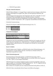
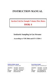
Key<br />
1 Entry nozzle 7 Dynamic pressure measurement<br />
2 Filter holder 8 Support tube („in stack“ device)<br />
3 Pitot tube 9 Cooling and drying system<br />
4 Temperature sensor 10 Suction unit and gas metering device<br />
5 Temperature indicator 11 Pressure gauge<br />
6 Static pressure measurement<br />
Figure 3 — Example of "in-stack" filter sampling system<br />
6
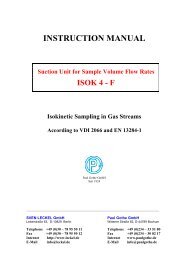
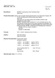
Key<br />
1 Entry nozzle 7 Dynamic pressure measurement<br />
2 Filter holder 8 Suction tube („out-stack“ device)<br />
3 Pitot tube 9 Cooling and drying system<br />
4 Temperature sensor 10 Suction unit and gas metering device (see Figure 5)<br />
5 Temperature indicator 11 Pressure gauge<br />
6 Static pressure measurement<br />
Figure 4 — Example of "out-stack" filter sampling system<br />
7
The sampling parts of the system have to be made of corrosion resistant and, if necessary, heat resistant material, e.g.<br />
stainless steel, titanium, quartz or glass.<br />
The surfaces of parts upstream the filter shall be smooth and well polished and the number of joints shall be kept to a<br />
minimum.<br />
Any changes in bore diameter shall be smoothly tapered and not stepped.<br />
The sampling equipment shall also be designed in order to facilitate the cleaning of internal parts upstream the filter.<br />
All parts of the equipment which come in contact with the sample shall be protected from contamination during<br />
handling, transportation, etc.<br />
Entry nozzle<br />
The sample gas stream to be measured enters the sampling equipment via the nozzle. The nozzle is connected either<br />
to the suction tube or to the filter holder.<br />
In order to allow isokinetic sampling of gases flowing at a wide range of velocities (e.g. 3 m/s to 50 m/s) without major<br />
change of the sampled flow rate, the sampling equipment shall be supplied with a set of nozzles of different diameters.<br />
The entry nozzle shall be sharp in order not to disturb the main gas flow.<br />
For this reason, it is recommended to use nozzles of inside diameter exceeding 8 mm, and diameters less than 6 mm<br />
shall be avoided.<br />
Filter holder<br />
The filter holder is a casing in which the filter support and the filter are mounted. When the filter holder is placed "outstack"<br />
it shall be temperature controlled to maintain filtration conditions and to avoid condensation.<br />
The filter holder and the filter support shall be designed in such a way that no gas turbulence will occur near the joints.<br />
To reduce the filter pressure drop and to improve the distribution of dust on the filter, a coarse grain filter support (e.g. fibre<br />
mesh) should be used.<br />
Filters<br />
The filters to be used shall comply with the following minimum requirements:<br />
a) plane filter efficiency better than 99,5 % on a test aerosol with a mean particle diameter of 0,3 µm, at the maximum<br />
flow rate anticipated, (or 99,9 % on a test aerosol of 0,6 µm mean diameter). This efficiency shall be certified by the<br />
filter supplier;<br />
b) the filter material shall not react with or adsorb gaseous compounds contained in the gas to be sampled, and shall<br />
be thermally stable, taking into account maximum temperature anticipated (conditioning, sampling etc.).<br />
The choice of the filter should also take into account the following considerations:<br />
a) the pressure drop of the filter, and increase due to the collection of the dust while sampling. This depends on the kind of<br />
filter. As an example the pressure drop can be between from 3 kPa to 10 kPa for a filtration velocity in the range of 0,5 m/s;<br />
b) when using filters with organic binders, care shall be taken of possible weight variations due to binder losses by<br />
8
evaporation when heating;<br />
c) glass fibre filters may react with acidic compounds such as SO3, which leads to an increase in weight; their use is not<br />
recommended;<br />
d) despite their weak mechanical properties quartz fibre filters are proven to be efficient in most cases;<br />
e) PTFE filters are also proven to be efficient, however the maximum allowable temperature of the gas passing through<br />
the filter shall not exceed 230 °C (refer to filter suppliers information).<br />
Suction unit and gas metering devices<br />
The suction unit shall be tight, corrosion-proof and shall be capable of extracting the maximum rated flow rate in the sampling<br />
conditions (vacuum of the suction side up to e.g. 40 kPa). Wide adjustments of sampled flow rate shall be controlled by a<br />
regulating valve and/or by-pass. A shut off valve shall also be available to shut-off the gas flow through the sampling train.<br />
Examples of two kinds of gas metering systems that may be used are as follows:<br />
flow rate measurements on a dry basis<br />
1) condenser and/or gas drying tower providing a residual humidity less than 10 g/m 3 at the maximum flow rate;<br />
2) gas-tight pump;<br />
3) flow meter, in order to facilitate the flow rate adjustment, calibrated against the dry gas volume meter;<br />
4) dry gas volume meter (uncertainty less than 2 % at the anticipated flow rate) with associated absolute pressure<br />
and absolute temperature measurement<br />
7. Equipment for weighing<br />
a) weighing containers for the drying procedure of the rinsing solutions. The mass shall be in accordance with the<br />
balance to be used. Glass and ceramic have proven to be suitable materials. Plastic materials are not recommended;<br />
b) desiccators: located in the weighing room, with a desiccating agent (silica gel, calcium chloride);<br />
c) drying oven: laboratory drying oven, thermally controlled within ± 5 °C;<br />
d) balance: resolution from 0,01 mg to 0,1 mg, the range is to be compatible with the mass of parts to be weighed (see<br />
6.2.6). Depending on the balance room location, specific care shall be required to avoid reading instability related to<br />
vibrations, air draughts and temperature variations;<br />
8 Weighing procedure<br />
Depending on the kind of sampling device to be used, the parts to be weighed can be the filter with or without its support,<br />
or may also include all upstream parts from the filter.<br />
9
Depending on the procedure to be used the rinsing solutions can be evaporated and weighed in the same container or<br />
transferred to a smaller container for weighing.<br />
Pre-sampling conditioning<br />
Weighed parts shall be dried in a drying oven for at least 1 h, at a minimum of 180 °C.<br />
The filters and/or the weighing containers are cooled down to ambient temperature in a desiccator located in the weighing<br />
room for at least 4 h. For larger parts e.g. weighing containers up to 12 h may be necessary. If the humidity is controlled and<br />
dust is not hygroscopic the filters and/or the weighing containers may be equilibrated in the weighing room.<br />
Weighing<br />
Since dust concentration is determined by difference between weights often obtained at one or two weeks interval,<br />
special care is required in order to avoid weighing errors related to balance drift, to insufficient temperature equilibrium of parts<br />
to be weighed, and to climatic changes. Therefore, before performing any measurement, the user shall validate their weighing<br />
procedure. It is strongly recommended to use the same balance for both pre-weighing and past weighing.<br />
Before each weighing series:<br />
a) the balance shall be checked against standard weights;<br />
b) additional check shall be carried out by weighing control parts, identical to the parts to be used in the<br />
measurement, pre-treated in the same temperature and humidity control conditions and kept free from<br />
contamination;<br />
c) record the climatic conditions in the room.<br />
When weighing large volume parts (e.g. beakers), the temperature and barometric pressure may influence the apparent<br />
weight, this may be detected using the reference weight of the control parts. In these conditions, weighing corrections shall<br />
be applied, based on the apparent weight modification of three identical control parts of each type (filter incl. support, container<br />
etc.).<br />
Attention has also to be drawn on an increase or decrease in weighing due to:<br />
a) electrostatic charges, which give erratic readings and which may have to be discharged/neutralised (metallic plate, ion<br />
gun);<br />
b) hygroscopic characteristics of the filter material and/or dust. Weighing shall be carried out within 3 min after removal<br />
from the desiccator. Three readings shall be taken at 1 min, 2 min and 3 min. If a significant increase is detected, the<br />
sample shall be put back into the desiccator for at least 4 h and then the weighing procedure shall be repeated.<br />
The dry reference weight shall then be calculated by extrapolation to zero time;<br />
c) small differences in temperature between the part to be weighed and the environment may disturb the balance.<br />
Post-sampling treatment of weighed parts<br />
Weighed parts shall be dried in an oven for at least 1 h at 160 °C.<br />
Afterwards they will be equilibrated to ambient temperature as described.<br />
All the rinsing solutions (water and acetone) from all parts upstream of the filter are taken to the laboratory for the further<br />
treatment. Care shall be taken that no contamination occurs.<br />
10
The solutions are transferred carefully to the dried and pre weighed containers. During the evaporation the solvent mixture<br />
shall not be boiled. As the volume of solution is reduced through the evaporation process, small vessels may be used before<br />
the final weighing container.<br />
9. Sampling procedure<br />
For sampling times limited to 30 min, required for certain trial or regulatory purposes, the uncertainty of measurement is<br />
in the range of 2 mg/m 3 . Furthermore, completion of sampling along two diameters within 30 min necessitates, even for<br />
medium size ducts, simultaneous sampling with two teams, one on each sampling line.<br />
Where possible, the sampling time can be extended, which decreases the detection limit to more practicable conditions .<br />
The sampling time should be determined, to minimize the effect of non steady state conditions of the stationary source<br />
and chemical reactions on collected dust on the filter.<br />
Preparation<br />
The equipment shall be cleaned, prepared and checked before moving to site. Care shall be taken not to reuse any part of<br />
a sampling train previously used for high dust concentration sampling without dismantling and thorough cleaning.<br />
The equipment shall be mechanical cleaned and rinsed before the measuring series.<br />
Depending on the measurement programme, filters and associated parts to be weighed shall be prepared for each<br />
measurement series. This includes the parts for the overall blank tests and spare parts e.g. filters, filter holder, nozzles,<br />
etc., to cope with process and equipment malfunctions.<br />
All the weighed parts, the suction tube and the other parts of the equipment which will come in contact with the<br />
sample (and will be rinsed later) shall be protected from contamination during transportation and storage.<br />
Measure the temperatures and velocities of the gas at the selected points in the duct, checking also for possible<br />
deviations of gas flow with regard to duct axis; verify that the requirements are fulfilled.<br />
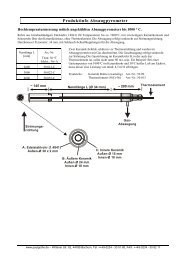
In order to check for possible flow rate variations in the duct while sampling, install a Pitot tube or another suitable<br />
measurement device at a relevant fixed point of the sampling plane for the monitoring of the velocity.<br />
The monitoring of the temperature in the duct and/or CO2/O2 concentration (or other relevant parameter) may provide additional information<br />
on the steadiness of the stationary source. The flue gas composition, especially the concentration of oxygen, CO2 and water shall<br />
be determined.<br />
Taking into account the preliminary calculations and the measured velocities, select a suitable entry nozzle diameter which<br />
shall fulfil isokinetic conditions for all the sampling points.<br />
Sampling procedure<br />
a) Assemble the sampling equipment, and check for possible leak by sealing the nozzle and starting the suction device.<br />
The leak flow e.g. measured by pressure variation after evacuation of the train at the maximal under pressure reached<br />
during sampling shall be below 2 % of the normal flow rate. During sampling, a leak check can be monitored by measuring<br />
continuously the concentration of a relevant gas component (CO2, O2, etc.) directly in the duct and downstream the<br />
sampling train; any detectable difference between those concentrations indicates a leak in the sampling equipment parts<br />
located out of the stack. This leak shall be then be investigated and rectified;<br />
b) preheat the relevant parts of the sampling train to the selected filtration temperature, e.g. stack temperature or<br />
recommended temperature of 160 °C ± 5 °C. Insert it into the duct with the nozzle, if possible, facing downstream<br />
avoiding contact with any parts of the duct;<br />
11
Seal up the opening of the access port in order to minimise air ingress in the duct or exposure of operators to toxic<br />
gases;<br />
c) turn the sampling probe until the entry nozzle is facing upstream within ± 10°, open the shut off valve, start the suction<br />
device and adjust the flow rate in order to obtain isokinetic sampling within –5 % and +15 %;<br />
d) the sampling duration at each selected point shall be identical;<br />
e) the total sampling duration shall be at least 30 min;<br />
f) during sampling, check at least every 5 min and adjust the flow rate for isokinetic sampling within –5 % and + 15 %.<br />
Continuously monitor, or record at least every 5 min, the dynamic pressure measured by the Pitot tube or another<br />
suitable measurement system either installed at the fixed point or mounted on the sampling equipment;<br />
g) do not stop sampling when moving the sampling train to the following sampling point, and immediately adjust the flow<br />
rate for isokinetic conditions;<br />
h) record the sampling time and sampled volume or flow rate at each sampling point;<br />
i) on completion of sampling at all the selected points of the sampling line, close the shut off valve and suction device,<br />
remove the sampling train from the duct and reposition it on the next sampling line;<br />
j) on completion of sampling run at all points:<br />
1) remove the sample train after closing the shut off valve and suction device;<br />
2) leak check the equipment if leakage has not been monitored during sampling;<br />
3) dismantle the sampling equipment and check visually the filter and the filter holder, for signs of breakage or stains<br />
due to pressure or to the concentration of moisture (sampling equipment operated below or too close the dew<br />
point). In such cases, the test is not valid. Check also non uniform distribution of dust on the filter.<br />
k) measure and record the barometric pressure.<br />
l) put the parts to be weighed in a closed electrostatic free container for transport to laboratory for weighing.<br />
Recovery of deposits upstream of the filter<br />
All the non weighed parts upstream of the filter which are in contact with the gas sample shall be rinsed to recover the<br />
deposits unless the quantification of possible deposits is not required.<br />
Special care has to be taken to avoid contamination if the rinsing is done on site. Rinsing shall be done in<br />
accordance with the following procedure:<br />
a) rinse the nozzle, elbow and the other parts upstream of the filter carefully with water into a storage container, taking<br />
care that nothing from the outside may fall into the container. The procedure is repeated with a second rinsing of<br />
water followed by acetone into the same container;<br />
b) to rinse the suction tube seal one end and fill enough water to wet and clean the inner surface (1/3 to 1/2 of the volume<br />
of the suction tube) and then seal the other end. The tube is cleaned by rotating and tilting several times. Transfer the<br />
solution to the transport storage container. The procedure is repeated with a second rinsing of water followed by<br />
acetone into the same container.<br />
12
No mechanical cleaning shall be applied to recover dust deposits upstream of the filter.<br />
The upstream parts shall be rinsed at least after each measurement series on the same sampling plane and at least once a<br />
day. The recovered mass shall be attributed to individual tests in proportion to the mass collected on each filter.<br />
Overall blank sample<br />
An overall blank sample shall be taken after each measurement series or at least once a day, following the sampling<br />
procedure without starting the suction device. This leads to an estimation of the dispersion of results related to the<br />
whole procedure as carried out by the operators for a near zero dust concentration i.e. contamination of filters and<br />
of rinsing solutions during handling on site, transport, storage, handling in the laboratory and weighing procedures.<br />
All overall blank values shall be reported individually.<br />
Thermal behaviour of dusts<br />
Emitted dusts are generally thermally stable. However, on some processes the gases to be sampled contain unstable or<br />
semi-volatile compounds (i.e. in particulate form at low temperature, in gaseous form at higher temperature). In such a case<br />
the measured concentration depends on the filtration temperature and/or on the drying temperature before final weighing.<br />
Differences in the measured dust concentrations (up to factor 10) have been experienced and therefore in such cases the<br />
measured results shall be associated with a stated temperature (i.e. the highest temperature sustained by the sampled<br />
dust before weighing).<br />
Because of the extreme variety of the situations, which may be encountered, it is not possible to find a conventional<br />
temperature which can be relevant in all the cases.<br />
However, since the complete trapping of volatile compounds would necessitate a very low filtration temperature and special<br />
care during sampling, more reproducible results may be achieved if these compounds are not trapped or are further<br />
evaporated when drying. It is the reason why a conventional temperature of 160 °C, which leads to avoid trapping of most<br />
volatile compounds and to decompose most of hydrates is generally convenient.<br />
In accordance with this convention, parts of the sampling train to be weighed should therefore be:<br />
a) conditioned at 180 °C before sampling;<br />
b) set at any temperature equal or less than 160 °C during sampling;<br />
c) conditioned at 160 °C after sampling.<br />
Depending on eventual regulatory requirements and plant authorisation, or on special kind of effluent or on specific objective<br />
of the measurement, other conventional temperature can be adopted: e.g. the temperature should be reduced during postsampling<br />
treatment if aerosols or condensable compounds are to be taken into account.<br />
In any case:<br />
a) the weighed parts shall be conditioned before sampling at a temperature at least 20 °C above the maximum<br />
temperature reached during sampling and post-sampling treatment;<br />
b) the temperature used while sampling and while conditioning before weighing shall be indicated in the test report.<br />
13
Isokinetic rate<br />
If the mean actual isokinetic rate during the sampling at the sampling plane differs for more than –5 % to +15 %, the<br />
measurement is not valid.<br />
If this criterion is not fulfilled due to frequent variation of the flow rate in the duct, see 10.2. 10.5<br />
Deposits of dust on non-weighed parts upstream the filter<br />
Experimental work carried out when preparing this Standard proved that dust deposits upstream of the<br />
filter are often in the range of 10 % to 30 % of the total dust when sampling gases from waste incinerators at<br />
concentration around 5 mg/m 3 .<br />
These deposits depend probably on the design of the sampling equipment, and on the kind of dust to be sampled, but no<br />
efficient means was found to keep them at a negligible level. For this reason all non weighed parts of the sampling<br />
equipment prior to the filter shall be rinsed. The mass of dust on non-weighed parts upstream of the filter shall be<br />
indicated in the test report, besides the mass on the filters used during the same measurement series.<br />
When sampling with in-stack filtration devices with no bends between the nozzle and filter holder on non saturated gases, with<br />
a temperature well above the stack gas dew point, the upstream deposits do not have to be quantified provided that<br />
validation has been carried out at similar conditions as the process to prove that the deposits, expressed in the same<br />
units as the measurement results (e.g. in milligrams per cubic metre) do not exceed 10 % of the daily average limit value<br />
set for the process.<br />
Calculation<br />
See our formula sheet or ask for our excel file.<br />
14
10. Determination of flow direction with Pitot tubes<br />
Type Prandtl-Pitot tube<br />
The type Prandtl Pitot tube provides an accurate measure of gas velocity when the Pitot tube is aligned (yawed) within<br />
15° of the direction of the gas flow. However, the pressure difference between the two pressure-sensing orifices decreases<br />
sharply when misalignment exceeds 15°, until a negative response occurs when the head is at 90° to the gas flow. This<br />
provides a simple method for estimating gas flow direction and may be used to test for the presence of swirling flow within<br />
the duct.<br />
Type S Pitot tube<br />
The type S Pitot tube accurately measures the gas velocity to within 4 % when the Pitot tube is aligned (yawed) within 15°<br />
of the direction of the gas flow. However, when the planes of the Pitot tube pressure-sensing orifices are parallel to the stack<br />
flow, a null (zero) reading is obtained. Thus, the direction of swirling flow can be determined by rotating the type S Pitot tube<br />
(with the manometer properly zeroed and levelled) until a null reading is obtained. The direction of flow shall be parallel to<br />
the pressure-sensing orifice planes.<br />
15
11. Sampling points in circular and rectangular ducts<br />
Circular ducts<br />
There are two methods for determining the position of sampling points in circular ducts as described in C.1.2 and C.1.3.<br />
Both methods are considered equivalent.<br />
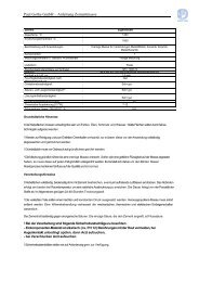
In the "general method" applicable to circular ducts, the sampling plane is divided into equal areas. The sampling<br />
points, one at the centre of each area, are located on two or more diameters (sampling lines), and one point at the<br />
centre of the duct (see Figure C.1).<br />
Figure C.1 — Sampling point positions in circular ducts - General method<br />
(showing positions for ducts over 2 m in diameter -<br />
The shaded positions are of equal area)<br />
The locations of the sampling points are dependant on the number of sample points chosen.<br />
For circular ducts two sampling lines (diameters) are sufficient, the distance can calculate by the formula shown in our<br />
data sheet<br />
16
Table C.1 gives values of Ki as a percentage, where nd is the number of sampling points per sampling line<br />
(diameter) and i is the number of individual sampling points along the diameter.<br />
i<br />
Table C.1 — Values of Ki as a percentage - General method for circular ducts<br />
Ki<br />
nd = 3 nd = 5 nd = 7 nd = 9<br />
1 11,3 5,9 4,0 3,0<br />
2 50,0 21,1 13,3 9,8<br />
3 88,7 50,0 26,0 17,8<br />
4 78,9 50,0 29,0<br />
5 94,1 74,0 50,0<br />
6 86,7 71,0<br />
7 96,0 82,2<br />
8 90,2<br />
9 97,0<br />
For circ ular ducts where it is necessary to increase the number of sampling lines (diameters) or the number of sampling<br />
points (because of adverse flow conditions for instance), the general formulae (see our data sheet.<br />
17
Tangential method for circular ducts<br />
In the "tangential method" applicable to circular ducts, the sampling plane is divided into equal areas. The sampling points, one at<br />
the centre of each area, are located on two or more diameters (sampling lines), there being no sampling point at the centre of the<br />
duct (see Figure C.2).<br />
Figure C.2 — Sampling point positions in circular ducts - Tangential method<br />
(showing positions for ducts over 2 m diameter)<br />
The locations of the sampling points on each diameter are dependent on the number of sampling points on each diameter but<br />
are independent of the number of sampling diameters.<br />
For circular ducts where two sampling lines (diameters) are sufficient, the distance can calculate by the formula in our<br />
data sheet.<br />
18
i<br />
Table C.2 — Values of Ki as a percentage - Tangential method for circular ducts<br />
Ki<br />
nd = 2 nd = 4 nd = 6 nd = 8<br />
1 14,6 6,7 4,4 3,3<br />
2 85,4 25,0 14,6 10,5<br />
3 75,0 29,6 19,4<br />
4 93,3 70,4 32,3<br />
5 85,4 67,7<br />
6 95,6 80,6<br />
7 89,5<br />
8 96,7<br />
Method for rectangular ducts<br />
In the method applicable to rectangular ducts, the sampling plane is divided into equal areas by lines parallel to the sides<br />
of the duct, and a sampling point is located at the centre of each area (see Figure C.3).<br />
In general, both sides of the rectangular duct are divided into an equal number of parts, giving areas which have the same<br />
shape as the duct. The number of partial areas is thus the square of 1, 2, 3, etc. (see Figure C.3 a).<br />
L1 and L2 being the dimensions of a section, where L1/L2 is greater than 2, side L1 shall be divided by a higher number<br />
than L2 so that for each of the partial sections, the ratio l1/l2 (partial section) is less than 2.<br />
If the lengths of the sides of the duct l1 and l2 are divided into n1 and n2 parts respectively, the number of sampling points<br />
is n1 times n2 and the smallest distance from a wall of the duct will be l1/2n1 and l2/2n2.<br />
19
2<br />
1<br />
1<br />
2<br />
Figure C.3 — Illustrations of sampling point positions in rectangular ducts<br />
20