Schrader Bellows - Parker
Schrader Bellows - Parker
Schrader Bellows - Parker

Create successful ePaper yourself
Turn your PDF publications into a flip-book with our unique Google optimized e-Paper software.
Catalog SB0106-6<br />
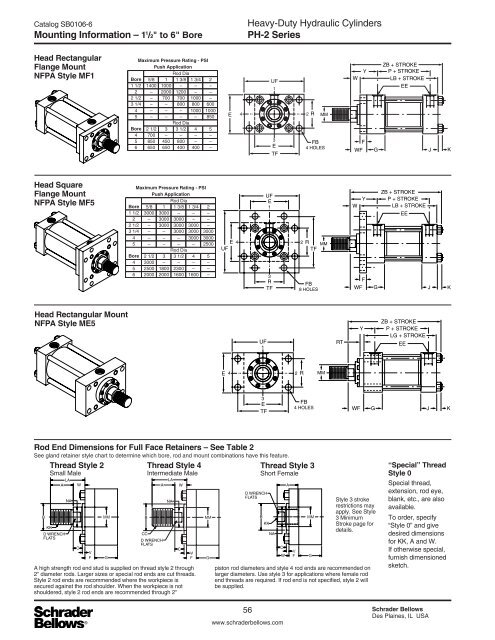
Mounting Information – 1 1 /2" to 6" Bore<br />
Heavy-Duty Hydraulic Cylinders<br />
PH-2 Series<br />
Head Rectangular<br />
Flange Mount<br />
NFPA Style MF1<br />
Maximum Pressure Rating - PSI<br />
Push Application<br />
Rod Dia<br />
Bore 5/8 1 1 3/8 1 3/4 2<br />
1 1/2 1400 1000 – – –<br />
2 – 2000 1200 – –<br />
2 1/2 – 700 700 1000 –<br />
3 1/4 – – 800 800 600<br />
4 – – – 1000 1000<br />
5 – – – – 850<br />
Rod Dia<br />
Bore 2 1/2 3 3 1/2 4 5<br />
4 700 – – – –<br />
5 850 450 800 – –<br />
6 650 650 400 400 –<br />
E<br />
UF<br />
E<br />
TF<br />
R<br />
MM<br />
FB<br />
4 HOLES<br />
Y<br />
W<br />
F<br />
WF<br />
G<br />
ZB + STROKE<br />
P + STROKE<br />
LB + STROKE<br />
EE<br />
J<br />
K<br />
Head Square<br />
Flange Mount<br />
NFPA Style MF5<br />
Maximum Pressure Rating - PSI<br />
Push Application<br />
Rod Dia<br />
Bore 5/8 1 1 3/8 1 3/4 2<br />
1 1/2 3000 3000 – – –<br />
2 – 3000 3000 – –<br />
2 1/2 – 3000 3000 3000 –<br />
3 1/4 – – 3000 3000 3000<br />
4 – – – 3000 3000<br />
5 – – – – 2500<br />
Rod Dia<br />
Bore 2 1/2 3 3 1/2 4 5<br />
4 3000 – – – –<br />
5 2500 1800 2300 – –<br />
6 2000 2000 1600 1600 –<br />
E<br />
UF<br />
UF<br />
E<br />
R<br />
TF<br />
R<br />
TF<br />
FB<br />
8 HOLES<br />
MM<br />
W<br />
Y<br />
ZB + STROKE<br />
P + STROKE<br />
LB + STROKE<br />
EE<br />
F<br />
WF G J K<br />
Head Rectangular Mount<br />
NFPA Style ME5<br />
UF<br />
RT<br />
ZB + STROKE<br />
P + STROKE<br />
LG + STROKE<br />
EE<br />
E<br />
R<br />
MM<br />
E<br />
TF<br />
FB<br />
4 HOLES<br />
WF<br />
G<br />
J<br />
K<br />
Rod End Dimensions for Full Face Retainers – See Table 2<br />
See gland retainer style chart to determine which bore, rod and mount combinations have this feature.<br />
Thread Style 2<br />
Thread Style 4<br />
Thread Style 3<br />
Small Male<br />
Intermediate Male<br />
Short Female<br />
B<br />
LA<br />
A<br />
KK<br />
D WRENCH<br />
FLATS<br />
NA<br />
W<br />
C<br />
V<br />
F<br />
MM<br />
G<br />
B<br />
A<br />
CC<br />
D WRENCH<br />
FLATS<br />
A high strength rod end stud is supplied on thread style 2 through<br />
2" diameter rods. Larger sizes or special rod ends are cut threads.<br />
Style 2 rod ends are recommended where the workpiece is<br />
secured against the rod shoulder. When the workpiece is not<br />
shouldered, style 2 rod ends are recommended through 2"<br />
LA<br />
NA<br />
W<br />
C<br />
V<br />
F<br />
MM<br />
G<br />
D WRENCH<br />
FLATS<br />
B<br />
KK<br />
NA<br />
C<br />
W<br />
A<br />
V<br />
F<br />
MM<br />
G<br />
Style 3 stroke<br />
restrictions may<br />
apply. See Style<br />
3 Minimum<br />
Stroke page for<br />
details.<br />
piston rod diameters and style 4 rod ends are recommended on<br />
larger diameters. Use style 3 for applications where female rod<br />
end threads are required. If rod end is not specified, style 2 will<br />
be supplied.<br />
“Special” Thread<br />
Style 0<br />
Special thread,<br />
extension, rod eye,<br />
blank, etc., are also<br />
available.<br />
To order, specify<br />
“Style 0” and give<br />
desired dimensions<br />
for KK, A and W.<br />
If otherwise special,<br />
furnish dimensioned<br />
sketch.<br />
56 <strong>Schrader</strong> <strong>Bellows</strong><br />
Des Plaines, IL USA<br />
www.schraderbellows.com