Schrader Bellows - Parker
Schrader Bellows - Parker
Schrader Bellows - Parker

You also want an ePaper? Increase the reach of your titles
YUMPU automatically turns print PDFs into web optimized ePapers that Google loves.
Catalog SB0106-6<br />
Mounting Information – 1 1 /2" to 6" Bore<br />
Heavy-Duty Hydraulic Cylinders<br />
PH-2 Series<br />
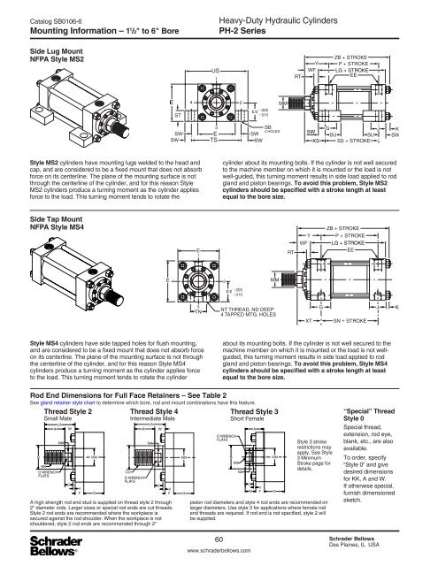
Side Lug Mount<br />
NFPA Style MS2<br />
LG + STROKE<br />
4<br />
SW<br />
XS<br />
Style MS2 cylinders have mounting lugs welded to the head and<br />
cap, and are considered to be a fixed mount that does not absorb<br />
force on its centerline. The plane of the mounting surface is not<br />
through the centerline of the cylinder, and for this reason Style<br />
MS2 cylinders produce a turning moment as the cylinder applies<br />
force to the load. This turning moment tends to rotate the<br />
cylinder about its mounting bolts. If the cylinder is not well secured<br />
to the machine member on which it is mounted or the load is not<br />
well-guided, this turning moment results in side load applied to rod<br />
gland and piston bearings. To avoid this problem, Style MS2<br />
cylinders should be specified with a stroke length at least<br />
equal to the bore size.<br />
Side Tap Mount<br />
NFPA Style MS4<br />
LG + STROKE<br />
Style MS4 cylinders have side tapped holes for flush mounting,<br />
and are considered to be a fixed mount that does not absorb force<br />
on its centerline. The plane of the mounting surface is not through<br />
the centerline of the cylinder, and for this reason Style MS4<br />
cylinders produce a turning moment as the cylinder applies force<br />
to the load. This turning moment tends to rotate the cylinder<br />
about its mounting bolts. If the cylinder is not well secured to the<br />
machine member on which it is mounted or the load is not wellguided,<br />
this turning moment results in side load applied to rod<br />
gland and piston bearings. To avoid this problem, Style MS4<br />
cylinders should be specified with a stroke length at least<br />
equal to the bore size.<br />
Rod End Dimensions for Full Face Retainers – See Table 2<br />
See gland retainer style chart to determine which bore, rod and mount combinations have this feature.<br />
Thread Style 2<br />
Thread Style 4<br />
Thread Style 3<br />
Small Male<br />
Intermediate Male<br />
Short Female<br />
B<br />
LA<br />
A<br />
KK<br />
D WRENCH<br />
FLATS<br />
NA<br />
W<br />
C<br />
V<br />
F<br />
MM<br />
G<br />
B<br />
A<br />
CC<br />
D WRENCH<br />
FLATS<br />
A high strength rod end stud is supplied on thread style 2 through<br />
2" diameter rods. Larger sizes or special rod ends are cut threads.<br />
Style 2 rod ends are recommended where the workpiece is<br />
secured against the rod shoulder. When the workpiece is not<br />
shouldered, style 2 rod ends are recommended through 2"<br />
LA<br />
NA<br />
W<br />
C<br />
V<br />
F<br />
MM<br />
G<br />
D WRENCH<br />
FLATS<br />
B<br />
KK<br />
NA<br />
C<br />
W<br />
A<br />
V<br />
F<br />
MM<br />
G<br />
Style 3 stroke<br />
restrictions may<br />
apply. See Style<br />
3 Minimum<br />
Stroke page for<br />
details.<br />
piston rod diameters and style 4 rod ends are recommended on<br />
larger diameters. Use style 3 for applications where female rod<br />
end threads are required. If rod end is not specified, style 2 will<br />
be supplied.<br />
“Special” Thread<br />
Style 0<br />
Special thread,<br />
extension, rod eye,<br />
blank, etc., are also<br />
available.<br />
To order, specify<br />
“Style 0” and give<br />
desired dimensions<br />
for KK, A and W.<br />
If otherwise special,<br />
furnish dimensioned<br />
sketch.<br />
60 <strong>Schrader</strong> <strong>Bellows</strong><br />
Des Plaines, IL USA<br />
www.schraderbellows.com