Schrader Bellows - Parker
Schrader Bellows - Parker
Schrader Bellows - Parker

Create successful ePaper yourself
Turn your PDF publications into a flip-book with our unique Google optimized e-Paper software.
BPL-2<br />
PH-2 Series<br />
Heavy-Duty<br />
Industrial Tie Rod<br />
Hydraulic Cylinders<br />
B<br />
PHX<br />
PH-3<br />
PH-2<br />
Contents<br />
Features.................................................................................50<br />
Specifications and Mountings................................................51<br />
Design Features...............................................................52-53<br />
Mounting Information........................................................54-65<br />
Spherical Bearing Mounting.............................................66-67<br />
Double Rod / Gland Retainer Style.......................................68<br />
Cylinder Accessories........................................................70-73<br />
Style 6 Piston Rod End.....................................................74-75<br />
How to Order....................................................................76-77<br />
Parts I.D. and Seal Kits......................................Sec. C, pg. 44<br />
Application Engineering Data......................Sec. C, pgs. 49-85<br />
SH/SHG SHM<br />
49<br />
www.schraderbellows.com<br />
<strong>Schrader</strong> <strong>Bellows</strong><br />
Des Plaines, IL USA
Catalog SB0106-6<br />
Features<br />
Heavy-Duty Hydraulic Cylinders<br />
PH-2 Series<br />
<strong>Schrader</strong> <strong>Bellows</strong><br />
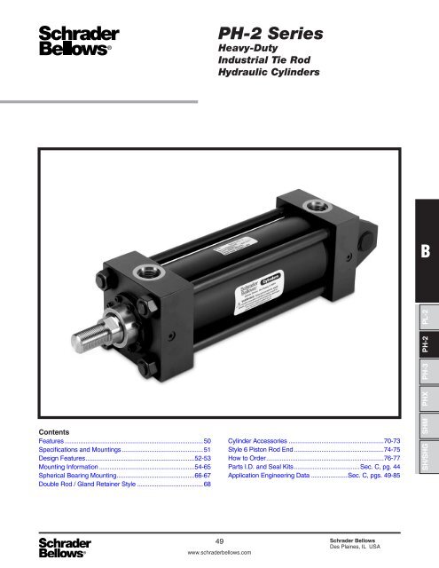
PH-2 Series<br />
Heavy-Duty<br />
Hydraulic Cylinder<br />
When the application demands a heavy-duty<br />
cylinder with maximum performance, specify<br />
<strong>Schrader</strong> <strong>Bellows</strong> PH-2 Series. This cylinder<br />
has standard design features to maximize<br />
machine uptime. The standard bronze rod<br />
gland, case-hardened piston rod, high strength<br />
piston rod stud and tie rod material combine<br />
to make the PH-2 Series the cylinder for<br />
demanding applications up to 3000 psi.<br />
Thorough inspection and performance testing<br />
of each cylinder before shipment assure<br />
PH-2 Series cylinder quality. See the following<br />
pages for the inside story on all the features that<br />
make PH-2 Series the high performance,<br />
long lasting choice for all your heavy-duty<br />
hydraulic applications.<br />
50 <strong>Schrader</strong> <strong>Bellows</strong><br />
Des Plaines, IL USA<br />
www.schraderbellows.com
BPL-2<br />
Catalog SB0106-6<br />
Specifications/Mountings<br />
Heavy-Duty Hydraulic Cylinders<br />
PH-2 Series<br />
Standard Specifications<br />
• Heavy Duty Service – ANSI/(NFPA) T3.6.7R2-1996<br />
Mounting and Specification Dimensions<br />
• Standard Construction – Square Head – Tie Rod Design<br />
• Nominal Pressure – 3000 P.S.I.*<br />
• Standard Fluid – Hydraulic Oil<br />
• Standard Temperature – -10° F to +165° F<br />
• Bore Sizes – 1 1 /2" through 6"<br />
• Piston Rod Diameter – 5 /8" through 4"<br />
• Mounting Styles – 16 standard styles at various<br />
application ratings<br />
• Standard – Externally removable bolted bushing assembly<br />
• Strokes – Available in any practical stroke length<br />
• Cushions – Optional at either end or both ends of stroke.<br />
“Float Check” at cap end.<br />
• Rod Ends – Three Standard Choices – Specials to Order<br />
* If hydraulic operating pressure exceeds 3000 P.S.I., send<br />
application data for engineering evaluation and recommendation.<br />
See Section C, Application Engineering Data for actual design<br />
factors.<br />
In line with our policy of continuing product improvement, specifications in this catalog are subject to change.<br />
Mounting Styles<br />
Tie Rods Extended Head Rectangular Flange Head Square Flange Head Rectangular<br />
BOTH ENDS NFPA MX1<br />
CAP END NFPA MX2<br />
HEAD END NFPA MX3<br />
NFPA MF1<br />
NFPA MF5<br />
NFPA ME5<br />
Cap Rectangular Flange Cap Square Flange Cap Rectangular Side Lug<br />
B<br />
NFPA MF2 NFPA MF6 NFPA ME6 NFPA MS2<br />
Side Tap Cap Fixed Clevis Cap Fixed Eye with<br />
Spherical Bearing<br />
Head Trunnion<br />
PH-2<br />
PH-3<br />
PHX<br />
NFPA MS4 NFPA MP1 NFPA MPU3 NFPA MT1<br />
Cap Trunnion<br />
Intermediate Trunnion<br />
SH/SHG SHM<br />
NFPA MT2<br />
NFPA MT4<br />
51<br />
www.schraderbellows.com<br />
<strong>Schrader</strong> <strong>Bellows</strong><br />
Des Plaines, IL USA
<strong>Schrader</strong> <strong>Bellows</strong> . . .<br />
PH-2 Series – your best choice in<br />
heavy duty hydraulic cylinders<br />
Primary Seal – New “Tri-Lip” Rod<br />
Seal is a proven leak proof design<br />
– completely self-compensating and<br />
self-relieving to withstand variations<br />
and conform to mechanical deflection<br />
that may occur.<br />
Steel Head – Bored and<br />
grooved to provide concentricity<br />
for mating parts.<br />
End Seal – Pressure-actuated<br />
cylinder tube-to-head and<br />
cap “O” rings.<br />
Piston Rod –<br />
Medium carbon steel,<br />
induction case-hardened,<br />
hard chromeplated<br />
and polished to<br />
10 RMS finish.<br />
Secondary Seal –<br />
Rod Wiper – wipes clean<br />
any oil film adhering to<br />
the rod on the extend<br />
stroke and cleans the<br />
rod on the return stroke.<br />
Piston Rod Stud –<br />
Furnished on 2" diameter<br />
rods and smaller when<br />
standard style #2 rod<br />
end threads are required.<br />
Studs have rolled threads<br />
and are made from high<br />
strength steel. Anaerobic<br />
adhesive is used to permanently<br />
lock the stud to<br />
the piston rod.<br />
Rod Gland Assembly –<br />
Standard bronze gland is<br />
externally removable without<br />
cylinder disassembly. (See<br />
gland retainer style chart<br />
for bore, rod and mount<br />
combinations that have this<br />
feature.) Long inboard bearing<br />
surface is ahead of the seals<br />
assuring lubrication by cylinder<br />
operating fluid.<br />
Alloy Steel Tie Rod Nuts<br />
Align-A-Groove –<br />
(Patent #3043639) – A 3 /16"<br />
wide surface machined at<br />
each end of the cylinder<br />
body. Makes precise<br />
mounting quick and easy.<br />
<strong>Schrader</strong> <strong>Bellows</strong> stepped floating<br />
cushions combine the best features<br />
of known cushion technology.<br />
Deceleration devices or built-in “cushions” are optional and can be supplied<br />
at head end, cap end, or both ends without change in envelope or<br />
mounting dimensions. <strong>Schrader</strong> <strong>Bellows</strong> cylinder cushions are a stepped<br />
design and combine the best features of known cushion technology.<br />
Standard straight or tapered cushions have been used in industrial<br />
cylinders over a very broad range of applications, <strong>Schrader</strong> <strong>Bellows</strong><br />
research has found that both designs have their limitations.<br />
As a result, <strong>Schrader</strong> <strong>Bellows</strong> has taken a new approach in cushioning of<br />
industrial hydraulic cylinders and for specific load and velocity conditions<br />
have been able to obtain deceleration curves that come very close to the<br />
ideal. The success lies in a stepped sleeve or spear concept where the<br />
steps are calculated to approximate theoretical orifice areas curves.<br />
In the cushion performance chart, pressure traces show the results of<br />
typical orifice flow conditions. Tests of a three-step sleeve or spear show<br />
three pressure pulses coinciding with the steps. The deceleration curve<br />
shape comes very close to being theoretical, with the exception of the<br />
last 1 /2 inch of travel.<br />
This is a constant shape in order to have some flexibility in application.<br />
The stepped cushion<br />
design shows reduced<br />
pressure peaks for<br />
most load and speed<br />
conditions, with<br />
comparable reduction<br />
of objectionable stopping<br />
forces being<br />
transmitted to the<br />
load and the support<br />
structure.<br />
All <strong>Schrader</strong> <strong>Bellows</strong><br />
PH-2 cushions are<br />
adjustable.<br />
The PH-2 Series<br />
cylinder design incorporates<br />
the longest<br />
cushion sleeve or<br />
spear that can be<br />
provided in the<br />
standard envelope<br />
without decreasing the<br />
rod bearing and piston<br />
bearing lengths.<br />
CUSHION PRESSURE<br />
CUSHION PERFORMANCE<br />
TYPICAL STRAIGHT CUSHION<br />
IDEAL CUSHION<br />
TYPICAL STEPPED<br />
CUSHION<br />
CUSHION POSITION<br />
52 <strong>Schrader</strong> <strong>Bellows</strong><br />
Des Plaines, IL USA<br />
www.schraderbellows.com
Adjustable Floating Stepped Cushions – For maximum<br />
performance – economical and flexible for even the most<br />
demanding applications – provides superior performance in<br />
reducing shock. Cushions are optional and can be supplied at<br />
head end, cap end, or both ends without change in envelope<br />
or mounting dimensions.<br />
Ports – S.A. E.<br />
“O”-ring ports are<br />
standard<br />
OPTIONAL PORTS<br />
Ports – N.P.T.F. ports<br />
are optional at no extra<br />
charge. Oversize N.P.T.F.<br />
and S.A.E. ports are<br />
available at extra charge.<br />
Gland Assembly with “Tri-Lip” Rod Seal<br />
Gland Assembly externally removable without cylinder<br />
disassembly. (See gland retainer style chart for bore, rod<br />
and mount combinations that have this feature.) An O-ring<br />
is used as a seal between the gland and head. The “Tri-Lip”<br />
rod seal has multiple sealing edges to produce “dry rod”<br />
performance. It is molded from a special polyurethane<br />
material that is extremely resistant to abrasion and extrusion,<br />
resulting in exceptional service life. Wiperseal cleans<br />
rod of dirt, preventing it from entering the gland and also<br />
acts as a secondary rod seal.<br />
OPTIONAL PISTONS<br />
Step cut iron piston rings are<br />
optional.<br />
Lipseal ® Piston – Zero<br />
leakage under static<br />
conditions for hydraulic<br />
pressures up to 3000 PSI.<br />
Seals are self-compensating<br />
to conform to variations in<br />
pressure, mechanical<br />
deflection, and wear.<br />
Back-up washer prevents<br />
extrusion.<br />
One-Piece Nodular Iron<br />
Piston – The wide piston<br />
surface contacting cylinder<br />
bore reduces bearing loads.<br />
Anaerobic adhesive is used to<br />
permanently lock and seal the<br />
piston to the rod.<br />
Steel Cap – Bored and<br />
grooved to provide<br />
concentricity for mating parts.<br />
High Strength Tie Rods –<br />
Made from 100,000 PSI<br />
minimum yield steel with<br />
rolled threads for<br />
added strength.<br />
The Cylinder Tube –<br />
Heavy-wall steel tubing,<br />
honed to a micro finish<br />
bore.<br />
FILLED<br />
PTFE<br />
BEARINGS<br />
BRONZE<br />
FILLED PTFE<br />
RINGS<br />
SYNTHETIC RUBBER<br />
EXPANDER RINGS<br />
Piston with Retainer Nut – Optional at<br />
no extra charge.<br />
Hi Load Piston – Optional at extra<br />
charge (1 1 /2 - 6" Bores). Includes wear<br />
rings and bronze-filled PTFE seals. Two<br />
wear rings serve as bearings which<br />
deform radially under side-loading,<br />
enabling the load to be spread over a<br />
larger area and reduce unit loading.<br />
Bronze-filled PTFE seals are designed<br />
for extrusion-free, leak-proof service and<br />
longer cylinder life than the lipseal type<br />
piston. Not available with retainer nut.<br />
B<br />
BPL-2<br />
PH-2<br />
(1) When a cushion is specified at the head end:<br />
a. A self-centering stepped sleeve is furnished on the piston rod<br />
assembly.<br />
b. A needle valve is provided that is flush with the side of the head<br />
even when wide open. It may be identified by the fact that it is<br />
socket-keyed. It is located on side number 2, in all mounting<br />
styles except MT1, MT2, MT4, ME5 and ME6. In these models it<br />
is located on side number 3.<br />
c. On 6" bore and larger cylinders, a springless check valve is<br />
provided that is also flush with the side of the head and is<br />
mounted adjacent to the needle valve except on Style MS2,<br />
where it is mounted opposite the needle valve. It may be<br />
identified by the fact that it is slotted.<br />
d. On 1 1 /2" - 5" bore cylinders a slotted sleeve design is used in<br />
place of the check valve.<br />
e. 1 1 /2" - 2 1 /2" bore<br />
cylinders use cartridge<br />
style needle valve<br />
(see Figure A).<br />
(2) When a cushion is specified at the cap end:<br />
a. A stepped spear is provided on the piston rod.<br />
b. A “float check” self-centering bushing is provided which<br />
incorporates a large flow check valve for fast “out-stroke”<br />
action.<br />
c. A socket-keyed needle valve is provided that is flush with the<br />
side of the cap when wide open. It is located on side number<br />
2 in all mounting styles except MT1, MT2, MT4, ME5 and ME6.<br />
In these models it is located on side number 3.<br />
STEPPED CUSHIONS<br />
ROD END SLEEVE<br />
CAP END SPEAR<br />
PH-3<br />
PHX<br />
SH/SHG SHM<br />
Figure A<br />
53<br />
www.schraderbellows.com<br />
<strong>Schrader</strong> <strong>Bellows</strong><br />
Des Plaines, IL USA
Catalog SB0106-6<br />
Mounting Information – 1 1 /2" to 6" Bore<br />
Heavy-Duty Hydraulic Cylinders<br />
PH-2 Series<br />
Tie Rods Extended Both Ends Mount<br />
NFPA Style MX1<br />
Y<br />
ZB + STROKE<br />
P + STROKE<br />
E<br />
1<br />
RT<br />
WF<br />
LG + STROKE<br />
EE<br />
DD<br />
AA<br />
E<br />
4<br />
2<br />
R<br />
MM<br />
3<br />
R<br />
K<br />
BB<br />
G<br />
J<br />
K<br />
BB<br />
Tie Rods Extended Cap End Mount<br />
NFPA Style MX2<br />
E<br />
1<br />
RT<br />
Y<br />
WF<br />
ZB + STROKE<br />
ZJ + STROKE<br />
P + STROKE<br />
LG + STROKE<br />
EE<br />
DD<br />
AA<br />
E<br />
4<br />
2<br />
R<br />
MM<br />
3<br />
R<br />
K<br />
G<br />
J<br />
K<br />
BB<br />
Tie Rods Extended Head End Mount<br />
NFPA Style MX3<br />
E<br />
1<br />
RT<br />
Y<br />
WF<br />
ZB + STROKE<br />
ZJ + STROKE<br />
P + STROKE<br />
LG + STROKE<br />
EE<br />
AA<br />
E<br />
4<br />
2<br />
R<br />
MM<br />
R<br />
3<br />
DD<br />
K<br />
BB<br />
G<br />
J<br />
K<br />
Rod End Dimensions for Full Face Retainers – See Table 2<br />
See gland retainer style chart to determine which bore, rod and mount combinations have this feature.<br />
B<br />
Thread Style 2<br />
Small Male<br />
LA<br />
A<br />
KK<br />
D WRENCH<br />
FLATS<br />
NA<br />
W<br />
C<br />
V<br />
F<br />
MM<br />
G<br />
Thread Style 4<br />
Intermediate Male<br />
B<br />
A<br />
CC<br />
D WRENCH<br />
FLATS<br />
A high strength rod end stud is supplied on thread style 2 through<br />
2" diameter rods. Larger sizes or special rod ends are cut threads.<br />
Style 2 rod ends are recommended where the workpiece is<br />
secured against the rod shoulder. When the workpiece is not<br />
shouldered, style 2 rod ends are recommended through 2"<br />
LA<br />
NA<br />
W<br />
C<br />
V<br />
F<br />
MM<br />
G<br />
D WRENCH<br />
FLATS<br />
Thread Style 3<br />
Short Female<br />
B<br />
KK<br />
NA<br />
C<br />
W<br />
A<br />
V<br />
F<br />
MM<br />
G<br />
Style 3 stroke<br />
restrictions may<br />
apply. See Style<br />
3 Minimum<br />
Stroke page for<br />
details.<br />
piston rod diameters and style 4 rod ends are recommended on<br />
larger diameters. Use style 3 for applications where female rod<br />
end threads are required. If rod end is not specified, style 2 will<br />
be supplied.<br />
“Special” Thread<br />
Style 0<br />
Special thread,<br />
extension, rod eye,<br />
blank, etc., are also<br />
available.<br />
To order, specify<br />
“Style 0” and give<br />
desired dimensions<br />
for KK, A and W.<br />
If otherwise special,<br />
furnish dimensioned<br />
sketch.<br />
54 <strong>Schrader</strong> <strong>Bellows</strong><br />
Des Plaines, IL USA<br />
www.schraderbellows.com
Catalog SB0106-6<br />
Mounting Information – 1 1 /2" to 6" Bore<br />
Heavy-Duty Hydraulic Cylinders<br />
PH-2 Series<br />
Table 1—Envelope and Mounting Dimensions<br />
EE<br />
Bore AA BB DD E NPTF O SAE H F G J K R<br />
1 1 /2<br />
2<br />
2 1 /2<br />
3 1 /4<br />
4<br />
5<br />
6<br />
2.3<br />
2.9<br />
3.6<br />
4.6<br />
5.4<br />
7.0<br />
8.1<br />
1 3 /8†<br />
1 13 /16†<br />
1 13 /16<br />
2 5 /16<br />
2 5 /16<br />
3 3 /16<br />
3 5 /8<br />
3 /8-24<br />
/2-20<br />
/2-20<br />
/8-18<br />
/8-18<br />
/8-14<br />
1-14<br />
2 1 /2<br />
3<br />
3 1 /2<br />
4 1 /2<br />
5<br />
6 1 /2<br />
7 1 /2<br />
1 /2<br />
/2<br />
/2<br />
/4<br />
/4<br />
/4<br />
1<br />
10<br />
10<br />
10<br />
12<br />
12<br />
12<br />
16<br />
3 /8<br />
/8<br />
/8<br />
/4<br />
/8<br />
/8<br />
1<br />
1 3 /4<br />
1 3 /4<br />
1 3 /4<br />
2<br />
2<br />
2<br />
2 1 /4<br />
1 1 /2<br />
1 1 /2<br />
1 1 /2<br />
1 3 /4<br />
1 3 /4<br />
1 3 /4<br />
2 1 /4<br />
3 /8<br />
/16<br />
/16<br />
/16<br />
/16<br />
/16<br />
/8<br />
1.63<br />
2.05<br />
2.55<br />
3.25<br />
3.82<br />
4.95<br />
5.73<br />
H<br />
SAE straight thread ports are standard and are indicated by port number.<br />
O NPTF ports are available at no extra charge.<br />
Add Stroke<br />
LG P<br />
4 5 /8<br />
4 5 /8<br />
4 3 /4<br />
5 1 /2<br />
5 3 /4<br />
6 1 /4<br />
7 3 /8<br />
2 7 /8<br />
2 7 /8<br />
3<br />
3 1 /2<br />
3 3 /4<br />
4 1 /4<br />
4 7 /8<br />
† 1 1/2" and 2" bore Styles MX1 and MX3 are only available with full face retainer<br />
construction (see gland retainer style chart). Head end ‘BB’ dimension for these<br />
bores is referenced from the front of full square retainer that is ‘F’ dimension thick.<br />
Table 2—Rod Dimensions<br />
Thread<br />
Rod Extensions and Pilot Dimensions<br />
Table 3 —<br />
Envelope<br />
and Mounting<br />
Dimensions<br />
Add Stroke<br />
Rod Style Style +.000<br />
Dia. 4 2 & 3 -.002 RD<br />
Bore MM CC KK A B C D LA LAF NA (Max.) RT V VF VH W WF Y ZB ZJ<br />
1 1 /2<br />
2<br />
5 /8<br />
1<br />
/2-20<br />
/8-14<br />
/16-20<br />
/4-16<br />
/4<br />
1 1 /8<br />
1.124<br />
1.499<br />
3 /8<br />
/2<br />
/2<br />
/8<br />
1 3 /8<br />
1 7 /8<br />
1 3 /4<br />
2 1 /2<br />
9 /16<br />
/16<br />
1 15 /16<br />
2 3 /8<br />
3 /8<br />
/8<br />
/4<br />
/4<br />
/4<br />
/2<br />
/16<br />
/16<br />
5 /8<br />
/4<br />
1<br />
1 3 /8<br />
2<br />
2 3 /8<br />
6<br />
6 7 /16<br />
5 5 /8<br />
6<br />
1<br />
1 3 /8<br />
/8-14<br />
1 1 /4-12<br />
/4-16<br />
1-14<br />
1 1 /8<br />
1 5 /8<br />
1.499<br />
1.999<br />
1 /2<br />
/8<br />
/8<br />
1 1 /8<br />
2 1 /8<br />
2 5 /8<br />
2 1 /2<br />
3 1 /4<br />
15 /16<br />
1 5 /16<br />
2 3 /8<br />
2 7 /8<br />
3 /8<br />
/8<br />
/2<br />
/8<br />
/2<br />
/8<br />
/16<br />
/16<br />
1<br />
1<br />
1 3 /8<br />
1 5 /8<br />
2 3 /8<br />
2 5 /8<br />
6 3 /8<br />
6 11 /16<br />
6<br />
6 1 /4<br />
2 1 /2<br />
3 1 /4<br />
4<br />
1<br />
1 3 /8<br />
1 3 /4<br />
1 3 /8<br />
1 3 /4<br />
2<br />
1 3 /4<br />
2<br />
2 1 /2<br />
2<br />
7 /8-14<br />
1 1 /4-12<br />
1 1 /2-12<br />
1 1 /4-12<br />
1 1 /2-12<br />
1 3 /4-12<br />
1 1 /2-12<br />
1 3 /4-12<br />
2 1 /4-12<br />
1 3 /4-12<br />
3 /4-16<br />
1-14<br />
1 1 /4-12<br />
1-14<br />
1 1 /4-12<br />
1 1 /2-12<br />
1 1 /4-12<br />
1 1 /2-12<br />
1 7 /8-12<br />
1 1 /2-12<br />
1 1 /8<br />
1 5 /8<br />
2<br />
1 5 /8<br />
2<br />
2 1 /4<br />
2<br />
2 1 /4<br />
3<br />
2 1 /4<br />
1.499<br />
1.999<br />
2.374<br />
1.999<br />
2.374<br />
2.624<br />
2.374<br />
2.624<br />
3.124<br />
2.624<br />
1 /2<br />
/8<br />
/4<br />
/8<br />
/4<br />
/8<br />
/4<br />
/8<br />
1<br />
/8<br />
7 /8<br />
1 1 /8<br />
1 1 /2<br />
1 1 /8<br />
1 1 /2<br />
1 11 /16<br />
1 1 /2<br />
1 11 /16<br />
2 1 /16<br />
1 11 /16<br />
–<br />
–<br />
–<br />
–<br />
–<br />
–<br />
–<br />
–<br />
–<br />
–<br />
2 1 /2<br />
3 1 /4<br />
3 7 /8<br />
3 1 /4<br />
3 7 /8<br />
4 1 /4<br />
3 7 /8<br />
4 1 /4<br />
5 1 /4<br />
4 1 /4<br />
15 /16<br />
1 5 /16<br />
1 11 /16<br />
1 5 /16<br />
1 11 /16<br />
1 15 /16<br />
1 11 /16<br />
1 15 /16<br />
2 3 /8<br />
1 15 /16<br />
2 3 /8<br />
2 7 /8<br />
3 15 /32<br />
2 7 /8<br />
3 15 /32<br />
3 23 /32<br />
3 15 /32<br />
3 23 /32<br />
4 1 /4<br />
3 23 /32<br />
3 /8<br />
/8<br />
/8<br />
/8<br />
/8<br />
/8<br />
/8<br />
/8<br />
/8<br />
/8<br />
1 /4<br />
/8<br />
/2<br />
/4<br />
/8<br />
/8<br />
/4<br />
/4<br />
/8<br />
/4<br />
1 /2<br />
/8<br />
/2<br />
/8<br />
/2<br />
/2<br />
/2<br />
/2<br />
/8<br />
/2<br />
3 /16<br />
/16<br />
/16<br />
/16<br />
/16<br />
/4<br />
/16<br />
/4<br />
/4<br />
/4<br />
–<br />
–<br />
–<br />
–<br />
–<br />
–<br />
–<br />
–<br />
–<br />
–<br />
1 3 /8<br />
1 5 /8<br />
1 7 /8<br />
1 5 /8<br />
1 7 /8<br />
2<br />
1 7 /8<br />
2<br />
2 1 /4<br />
2<br />
2 3 /8<br />
2 5 /8<br />
2 7 /8<br />
2 3 /4<br />
3<br />
3 1 /8<br />
3<br />
3 1 /8<br />
3 3 /8<br />
3 1 /8<br />
6 9 /16<br />
6 13 /16<br />
7 1 /16<br />
7 11 /16<br />
7 15 /16<br />
8 1 /16<br />
8 3 /16<br />
8 5 /16<br />
8 9 /16<br />
9 1 /16<br />
6 1 /8<br />
6 3 /8<br />
6 5 /8<br />
7 1 /8<br />
7 3 /8<br />
7 1 /2<br />
7 5 /8<br />
7 3 /4<br />
8<br />
8 1 /4<br />
5<br />
2 1 /2 2 1 /4-12 1 7 /8-12 3 3.124 1 2 1 /16 – 5 1 /4 3 3 /8 4 1 /4<br />
5 /8<br />
/8<br />
/8<br />
/4 – 2 1 /4 3 3 /8 9 5 /16 8 1 /2<br />
3 2 3 /4-12 2 1 /4-12 3 1 /2 3.749 1 2 5 /8 – 5 3 /4 2 7 /8 5 7 /16<br />
7 /8<br />
/8<br />
/16 – – 2 1 /4 3 3 /8 9 5 /16 8 1 /2<br />
3 1 /2<br />
2 1 /2<br />
3 1 /4-12<br />
2 1 /4-12<br />
2 1 /2-12<br />
1 7 /8-12<br />
3 1 /2<br />
3<br />
4.249<br />
3.124<br />
1<br />
1<br />
3<br />
2 1 /16<br />
–<br />
–<br />
5 3 /4<br />
5 1 /4<br />
2 3 /8<br />
2 3 /8<br />
5 15 /16<br />
4 1 /4<br />
15 /16<br />
/8<br />
3 /8<br />
/4<br />
5 /16<br />
/8<br />
–<br />
/4<br />
–<br />
–<br />
2 1 /4<br />
2 1 /4<br />
3 3 /8<br />
3 1 /2<br />
9 5 /16<br />
10 1 /2<br />
8 1 /2<br />
9 5 /8<br />
6<br />
3 2 3 /4-12 2 1 /4-12 3 1 /2 3.749 1 2 5 /8 – 5 3 /4 2 7 /8 5 7 /16<br />
7 /8<br />
/4<br />
/16 – – 2 1 /4 3 1 /2 10 1 /2 9 5 /8<br />
3 1 /2 3 1 /4-12 2 1 /2-12 3 1 /2 4.249 1 3 – 5 3 /4 3 3 /8 5 15 /16<br />
15 /16<br />
/4<br />
/16 – – 2 1 /4 3 1 /2 10 1 /2 9 5 /8<br />
4 3 3 /4-12 3-12 4 4.749 1 3 3 /8 – 6 1 /4 3 7 /8 6 5 /16<br />
15 /16<br />
1 /4<br />
5 /16 – – 2 1 /4 3 1 /2 10 1 /2 9 5 /8<br />
B<br />
PHX PH-3 PH-2<br />
BPL-2<br />
Rod End Dimensions for Bolted Retainers – See Table 2<br />
See gland retainer style chart to determine which bore, rod and mount combinations have this feature.<br />
B<br />
Thread Style 2<br />
Small Male<br />
A<br />
KK<br />
D WRENCH<br />
FLATS<br />
LAF<br />
WF<br />
VH<br />
NA<br />
C<br />
VF<br />
MM RD<br />
RT<br />
B<br />
Thread Style 4<br />
Intermediate Male<br />
A<br />
CC<br />
D WRENCH<br />
FLATS<br />
LAF<br />
WF<br />
VH<br />
NA<br />
C<br />
MM<br />
RT<br />
VF<br />
RD<br />
D WRENCH<br />
FLATS<br />
Thread Style 3<br />
Short Female<br />
B<br />
KK<br />
WF<br />
A<br />
VH<br />
MM RD<br />
NA<br />
C RT<br />
VF<br />
Style 3 stroke restrictions may apply. See<br />
Style 3 Minimum Stroke page for details.<br />
A high strength rod end stud<br />
is supplied on thread style<br />
2 through 2" diameter rods.<br />
Larger sizes or special rod<br />
ends are cut threads. Style 2<br />
rod ends are recommended<br />
where the workpiece is<br />
secured against the rod<br />
shoulder. When the workpiece<br />
is not shouldered, style 2<br />
rod ends are recommended<br />
through 2" piston rod<br />
diameters and style 4 rod<br />
ends are recommended on<br />
larger diameters. Use style 3<br />
for applications where female<br />
rod end threads are required.<br />
If rod end is not specified,<br />
style 2 will be supplied.<br />
“Special” Thread<br />
Style 0<br />
Special thread,<br />
extension, rod eye,<br />
blank, etc., are also<br />
available.<br />
To order, specify<br />
“Style 0” and give<br />
desired dimensions<br />
for KK, A and WF.<br />
If otherwise special,<br />
furnish dimensioned<br />
sketch.<br />
SH/SHG SHM<br />
55<br />
www.schraderbellows.com<br />
<strong>Schrader</strong> <strong>Bellows</strong><br />
Des Plaines, IL USA
Catalog SB0106-6<br />
Mounting Information – 1 1 /2" to 6" Bore<br />
Heavy-Duty Hydraulic Cylinders<br />
PH-2 Series<br />
Head Rectangular<br />
Flange Mount<br />
NFPA Style MF1<br />
Maximum Pressure Rating - PSI<br />
Push Application<br />
Rod Dia<br />
Bore 5/8 1 1 3/8 1 3/4 2<br />
1 1/2 1400 1000 – – –<br />
2 – 2000 1200 – –<br />
2 1/2 – 700 700 1000 –<br />
3 1/4 – – 800 800 600<br />
4 – – – 1000 1000<br />
5 – – – – 850<br />
Rod Dia<br />
Bore 2 1/2 3 3 1/2 4 5<br />
4 700 – – – –<br />
5 850 450 800 – –<br />
6 650 650 400 400 –<br />
E<br />
UF<br />
E<br />
TF<br />
R<br />
MM<br />
FB<br />
4 HOLES<br />
Y<br />
W<br />
F<br />
WF<br />
G<br />
ZB + STROKE<br />
P + STROKE<br />
LB + STROKE<br />
EE<br />
J<br />
K<br />
Head Square<br />
Flange Mount<br />
NFPA Style MF5<br />
Maximum Pressure Rating - PSI<br />
Push Application<br />
Rod Dia<br />
Bore 5/8 1 1 3/8 1 3/4 2<br />
1 1/2 3000 3000 – – –<br />
2 – 3000 3000 – –<br />
2 1/2 – 3000 3000 3000 –<br />
3 1/4 – – 3000 3000 3000<br />
4 – – – 3000 3000<br />
5 – – – – 2500<br />
Rod Dia<br />
Bore 2 1/2 3 3 1/2 4 5<br />
4 3000 – – – –<br />
5 2500 1800 2300 – –<br />
6 2000 2000 1600 1600 –<br />
E<br />
UF<br />
UF<br />
E<br />
R<br />
TF<br />
R<br />
TF<br />
FB<br />
8 HOLES<br />
MM<br />
W<br />
Y<br />
ZB + STROKE<br />
P + STROKE<br />
LB + STROKE<br />
EE<br />
F<br />
WF G J K<br />
Head Rectangular Mount<br />
NFPA Style ME5<br />
UF<br />
RT<br />
ZB + STROKE<br />
P + STROKE<br />
LG + STROKE<br />
EE<br />
E<br />
R<br />
MM<br />
E<br />
TF<br />
FB<br />
4 HOLES<br />
WF<br />
G<br />
J<br />
K<br />
Rod End Dimensions for Full Face Retainers – See Table 2<br />
See gland retainer style chart to determine which bore, rod and mount combinations have this feature.<br />
Thread Style 2<br />
Thread Style 4<br />
Thread Style 3<br />
Small Male<br />
Intermediate Male<br />
Short Female<br />
B<br />
LA<br />
A<br />
KK<br />
D WRENCH<br />
FLATS<br />
NA<br />
W<br />
C<br />
V<br />
F<br />
MM<br />
G<br />
B<br />
A<br />
CC<br />
D WRENCH<br />
FLATS<br />
A high strength rod end stud is supplied on thread style 2 through<br />
2" diameter rods. Larger sizes or special rod ends are cut threads.<br />
Style 2 rod ends are recommended where the workpiece is<br />
secured against the rod shoulder. When the workpiece is not<br />
shouldered, style 2 rod ends are recommended through 2"<br />
LA<br />
NA<br />
W<br />
C<br />
V<br />
F<br />
MM<br />
G<br />
D WRENCH<br />
FLATS<br />
B<br />
KK<br />
NA<br />
C<br />
W<br />
A<br />
V<br />
F<br />
MM<br />
G<br />
Style 3 stroke<br />
restrictions may<br />
apply. See Style<br />
3 Minimum<br />
Stroke page for<br />
details.<br />
piston rod diameters and style 4 rod ends are recommended on<br />
larger diameters. Use style 3 for applications where female rod<br />
end threads are required. If rod end is not specified, style 2 will<br />
be supplied.<br />
“Special” Thread<br />
Style 0<br />
Special thread,<br />
extension, rod eye,<br />
blank, etc., are also<br />
available.<br />
To order, specify<br />
“Style 0” and give<br />
desired dimensions<br />
for KK, A and W.<br />
If otherwise special,<br />
furnish dimensioned<br />
sketch.<br />
56 <strong>Schrader</strong> <strong>Bellows</strong><br />
Des Plaines, IL USA<br />
www.schraderbellows.com
Catalog SB0106-6<br />
Mounting Information – 1 1 /2" to 6" Bore<br />
Heavy-Duty Hydraulic Cylinders<br />
PH-2 Series<br />
Table 1—Envelope and Mounting Dimensions<br />
EE<br />
Add Stroke<br />
Bore E NPTF O SAE H F FB G J K R TF UF LB LG P<br />
1 1 /2 2 1 /2<br />
1 /2 10<br />
3 /8<br />
7 /16 1 3 /4 1 1 /2<br />
3 /8 1.63 3 7 /16 4 1 /4 5 4 5 /8<br />
2 3<br />
2 1 /2 3 1 /2<br />
3 1 /4 4 1 /2<br />
4<br />
5<br />
6<br />
5<br />
6 1 /2<br />
7 1 /2<br />
1 /2<br />
1 /2<br />
3 /4<br />
3 /4<br />
3 /4<br />
10<br />
10<br />
12<br />
12<br />
12<br />
5 /8<br />
5 /8<br />
3 /4<br />
7 /8<br />
7 /8<br />
1 16 1<br />
9 /16 1 3 /4 1 1 /2<br />
7 /16<br />
9 /16 1 3 /4 1 1 /2<br />
7 /16<br />
11 /16<br />
11 /16<br />
15 /16<br />
2<br />
2<br />
2<br />
1 3 /4<br />
9 /16<br />
1 3 /4<br />
9 /16<br />
1 3 /4<br />
13 /16<br />
1 1 /16 2 1 /4 2 1 /4<br />
7 /8<br />
H<br />
SAE straight thread ports are standard and are indicated by port number.<br />
O NPTF ports are available at no extra charge.<br />
2.05<br />
2.55<br />
3.25<br />
3.82<br />
4.95<br />
5.73<br />
4 1 /8<br />
4 5 /8<br />
5 7 /8<br />
6 3 /8<br />
8 3 /16<br />
9 7 /16<br />
5 1 /8<br />
5 5 /8<br />
7 1 /8<br />
7 5 /8<br />
9 3 /4<br />
11 1 /4<br />
5 1 /4<br />
5 3 /8<br />
6 1 /4<br />
6 5 /8<br />
7 1 /8<br />
8 3 /8<br />
4 5 /8<br />
4 3 /4<br />
5 1 /2<br />
5 3 /4<br />
6 1 /4<br />
7 3 /8<br />
2 7 /8<br />
2 7 /8<br />
3<br />
3 1 /2<br />
3 3 /4<br />
4 1 /4<br />
4 7 /8<br />
Table 2—Rod Dimensions<br />
Thread<br />
Rod Extensions and Pilot Dimensions<br />
Table 3 —<br />
Envelope<br />
and Mounting<br />
Dimensions<br />
Rod Style Style +.000<br />
Dia. 4 2 & 3 -.002 RD<br />
Bore MM CC KK A B C D LA LAF NA (Max.) RT V VF VH W WF Y ZB<br />
1 1 /2<br />
2<br />
5 /8<br />
1<br />
/2-20<br />
/8-14<br />
/16-20<br />
/4-16<br />
/4<br />
1 1 /8<br />
1.124<br />
1.499<br />
3 /8<br />
/2<br />
/2<br />
/8<br />
1 3 /8<br />
1 7 /8<br />
1 3 /4<br />
2 1 /2<br />
9 /16<br />
/16<br />
1 15 /16<br />
2 3 /8<br />
3 /8<br />
/8<br />
1 /4<br />
/4<br />
/4<br />
/2<br />
/16<br />
/16<br />
5 /8<br />
/4<br />
1<br />
1 3 /8<br />
2<br />
2 3 /8<br />
6<br />
6 7 /16<br />
1<br />
1 3 /8<br />
/8-14<br />
1 1 /4-12<br />
/4-16<br />
1-14<br />
1 1 /8<br />
1 5 /8<br />
1.499<br />
1.999<br />
1 /2<br />
/8<br />
/8<br />
1 1 /8<br />
2 1 /8<br />
2 5 /8<br />
2 1 /2<br />
3 1 /4<br />
15 /16<br />
1 5 /16<br />
2 3 /8<br />
2 7 /8<br />
3 /8<br />
/8<br />
1 /2<br />
/8<br />
/2<br />
/8<br />
/16<br />
/16<br />
1<br />
1<br />
1 3 /8<br />
1 5 /8<br />
2 3 /8<br />
2 5 /8<br />
6 3 /8<br />
6 11 /16<br />
2 1 /2<br />
3 1 /4<br />
4<br />
1<br />
1 3 /8<br />
1 3 /4<br />
1 3 /8<br />
1 3 /4<br />
2<br />
1 3 /4<br />
2<br />
2 1 /2<br />
2<br />
7 /8-14<br />
1 1 /4-12<br />
1 1 /2-12<br />
1 1 /4-12<br />
1 1 /2-12<br />
1 3 /4-12<br />
1 1 /2-12<br />
1 3 /4-12<br />
2 1 /4-12<br />
1 3 /4-12<br />
3 /4-16<br />
1-14<br />
1 1 /4-12<br />
1-14<br />
1 1 /4-12<br />
1 1 /2-12<br />
1 1 /4-12<br />
1 1 /2-12<br />
1 7 /8-12<br />
1 1 /2-12<br />
1 1 /8<br />
1 5 /8<br />
2<br />
1 5 /8<br />
2<br />
2 1 /4<br />
2<br />
2 1 /4<br />
3<br />
2 1 /4<br />
1.499<br />
1.999<br />
2.374<br />
1.999<br />
2.374<br />
2.624<br />
2.374<br />
2.624<br />
3.124<br />
2.624<br />
1 /2<br />
/8<br />
/4<br />
/8<br />
/4<br />
/8<br />
/4<br />
/8<br />
1<br />
/8<br />
7 /8<br />
1 1 /8<br />
1 1 /2<br />
1 1 /8<br />
1 1 /2<br />
1 11 /16<br />
1 1 /2<br />
1 11 /16<br />
2 1 /16<br />
1 11 /16<br />
1 7 /8<br />
2 5 /8<br />
3 1 /4<br />
2 1 /2<br />
3 1 /8<br />
3 1 /2<br />
3<br />
3 3 /8<br />
4 3 /8<br />
3 3 /8<br />
2 1 /2<br />
3 1 /4<br />
3 7 /8<br />
3 1 /4<br />
3 7 /8<br />
4 1 /4<br />
3 7 /8<br />
4 1 /4<br />
5 1 /4<br />
4 1 /4<br />
15 /16<br />
1 5 /16<br />
1 11 /16<br />
1 5 /16<br />
1 11 /16<br />
1 15 /16<br />
1 11 /16<br />
1 15 /16<br />
2 3 /8<br />
1 15 /16<br />
2 3 /8<br />
2 7 /8<br />
3 15 /32<br />
2 7 /8<br />
3 15 /32<br />
3 23 /32<br />
3 15 /32<br />
3 23 /32<br />
4 1 /4<br />
3 23 /32<br />
3 /8<br />
/8<br />
/8<br />
/8<br />
/8<br />
/8<br />
/8<br />
/8<br />
/8<br />
/8<br />
1 /4<br />
/8<br />
/2<br />
/4<br />
/8<br />
/8<br />
/4<br />
/4<br />
/8<br />
/4<br />
1 /2<br />
/8<br />
/2<br />
/8<br />
/2<br />
/2<br />
/2<br />
/2<br />
/8<br />
/2<br />
3 /16<br />
/16<br />
/16<br />
/16<br />
/16<br />
/4<br />
/16<br />
/4<br />
/4<br />
/4<br />
3 /4<br />
1<br />
1 1 /4<br />
/8<br />
1 1 /8<br />
1 1 /4<br />
1<br />
1 1 /8<br />
1 3 /8<br />
1 1 /8<br />
1 3 /8<br />
1 5 /8<br />
1 7 /8<br />
1 5 /8<br />
1 7 /8<br />
2<br />
1 7 /8<br />
2<br />
2 1 /4<br />
2<br />
2 3 /8<br />
2 5 /8<br />
2 7 /8<br />
2 3 /4<br />
3<br />
3 1 /8<br />
3<br />
3 1 /8<br />
3 3 /8<br />
3 1 /8<br />
6 9 /16<br />
6 13 /16<br />
7 1 /16<br />
7 11 /16<br />
7 15 /16<br />
8 1 /16<br />
8 3 /16<br />
8 5 /16<br />
8 9 /16<br />
9 1 /16<br />
5<br />
2 1 /2 2 1 /4-12 1 7 /8-12 3 3.124 1 2 1 /16 4 3 /8 5 1 /4 2 3 /8 4 1 /4<br />
5 /8<br />
3 /8<br />
/8<br />
/4 1 3 /8 2 1 /4 3 3 /8 9 5 /16<br />
3 2 3 /4-12 2 1 /4-12 3 1 /2 3.749 1 2 5 /8 4 7 /8 5 3 /4 2 7 /8 5 7 /16<br />
7 /8<br />
3 /8<br />
/16 – 1 3 /8 2 1 /4 3 3 /8 9 5 /16<br />
6<br />
3 1 /2<br />
2 1 /2<br />
3<br />
3 1 /2<br />
4<br />
3 1 /4-12<br />
2 1 /4-12<br />
2 3 /4-12<br />
3 1 /4-12<br />
3 3 /4-12<br />
2 1 /2-12<br />
1 7 /8-12<br />
2 1 /4-12<br />
2 1 /2-12<br />
3-12<br />
3 1 /2<br />
3<br />
3 1 /2<br />
3 1 /2<br />
4<br />
4.249<br />
3.124<br />
3.749<br />
4.249<br />
4.749<br />
1<br />
1<br />
1<br />
1<br />
1<br />
3<br />
2 1 /16<br />
2 5 /8<br />
3<br />
3 3 /8<br />
4 7 /8<br />
4 1 /4<br />
4 3 /4<br />
4 3 /4<br />
5 1 /4<br />
5 3 /4<br />
5 1 /4<br />
5 3 /4<br />
5 3 /4<br />
6 1 /4<br />
3 3 /8<br />
2 3 /8<br />
2 7 /8<br />
3 3 /8<br />
3 7 /8<br />
5 15 /16<br />
4 1 /4<br />
5 7 /16<br />
5 15 /16<br />
6 5 /16<br />
15 /16<br />
/8<br />
/8<br />
/16<br />
/16<br />
3 /8<br />
/4<br />
/4<br />
/4<br />
/4<br />
5 /16<br />
/8<br />
/16<br />
/16<br />
/16<br />
–<br />
/4<br />
–<br />
–<br />
–<br />
1 3 /8<br />
1 1 /4<br />
1 1 /4<br />
1 1 /4<br />
1 1 /4<br />
2 1 /4<br />
2 1 /4<br />
2 1 /4<br />
2 1 /4<br />
2 1 /4<br />
3 3 /8<br />
3 1 /2<br />
3 1 /2<br />
3 1 /2<br />
3 1 /2<br />
9 5 /16<br />
10 1 /2<br />
10 1 /2<br />
10 1 /2<br />
10 1 /2<br />
Add<br />
Stroke<br />
B<br />
PHX PH-3 PH-2<br />
BPL-2<br />
Rod End Dimensions for Bolted Retainers – See Table 2<br />
See gland retainer style chart to determine which bore, rod and mount combinations have this feature.<br />
B<br />
Thread Style 2<br />
Small Male<br />
A<br />
KK<br />
D WRENCH<br />
FLATS<br />
LAF<br />
WF<br />
VH<br />
NA<br />
C<br />
VF<br />
MM RD<br />
RT<br />
B<br />
Thread Style 4<br />
Intermediate Male<br />
A<br />
CC<br />
D WRENCH<br />
FLATS<br />
LAF<br />
WF<br />
VH<br />
NA<br />
C<br />
MM<br />
RT<br />
VF<br />
RD<br />
D WRENCH<br />
FLATS<br />
Thread Style 3<br />
Short Female<br />
B<br />
KK<br />
WF<br />
A<br />
VH<br />
MM RD<br />
NA<br />
C RT<br />
VF<br />
Style 3 stroke restrictions may apply. See<br />
Style 3 Minimum Stroke page for details.<br />
A high strength rod end stud<br />
is supplied on thread style<br />
2 through 2" diameter rods.<br />
Larger sizes or special rod<br />
ends are cut threads. Style 2<br />
rod ends are recommended<br />
where the workpiece is<br />
secured against the rod<br />
shoulder. When the workpiece<br />
is not shouldered, style 2<br />
rod ends are recommended<br />
through 2" piston rod<br />
diameters and style 4 rod<br />
ends are recommended on<br />
larger diameters. Use style 3<br />
for applications where female<br />
rod end threads are required.<br />
If rod end is not specified,<br />
style 2 will be supplied.<br />
“Special” Thread<br />
Style 0<br />
Special thread,<br />
extension, rod eye,<br />
blank, etc., are also<br />
available.<br />
To order, specify<br />
“Style 0” and give<br />
desired dimensions<br />
for KK, A and WF.<br />
If otherwise special,<br />
furnish dimensioned<br />
sketch.<br />
SH/SHG SHM<br />
57<br />
www.schraderbellows.com<br />
<strong>Schrader</strong> <strong>Bellows</strong><br />
Des Plaines, IL USA
Catalog SB0106-6<br />
Mounting Information – 1 1 /2" to 6" Bore<br />
Heavy-Duty Hydraulic Cylinders<br />
PH-2 Series<br />
Cap Rectangular<br />
Flange Mount<br />
NFPA Style MF2<br />
Maximum Pressure Rating - PSI<br />
Pull Application<br />
Rod Dia<br />
Bore 5/8 1 1 3/8 1 3/4 2<br />
1 1/2 2500 3000 – – –<br />
2 – 3000 3000 – –<br />
2 1/2 – 3000 3000 3000 –<br />
3 1/4 – – 3000 3000 3000<br />
4 – – – 3000 3000<br />
5 – – – – 2000<br />
Rod Dia<br />
Bore 2 1/2 3 3 1/2 4 5<br />
4 3000 – – – –<br />
5 2000 2500 3000 – –<br />
6 1800 2000 2000 2500 –<br />
MM<br />
Y<br />
WF<br />
ZF + STROKE<br />
P + STROKE<br />
LG + STROKE<br />
EE<br />
RT<br />
G<br />
XF + STROKE<br />
J<br />
F<br />
R 2<br />
FB<br />
4 HOLES<br />
UF<br />
1<br />
3<br />
E<br />
TF<br />
4 E<br />
Cap Square Flange Mount<br />
NFPA Style MF6<br />
WF<br />
ZF + STROKE<br />
P + STROKE<br />
LG + STROKE<br />
EE<br />
UF<br />
E<br />
1<br />
MM<br />
R 2<br />
TF<br />
4 E<br />
UF<br />
RT<br />
G<br />
XF + STROKE<br />
J<br />
F<br />
FB<br />
8 HOLES<br />
3<br />
R<br />
TF<br />
Cap Rectangular Mount<br />
NFPA Style ME6<br />
Y<br />
WF<br />
P + STROKE<br />
LG + STROKE<br />
EE<br />
UF<br />
1<br />
MM<br />
R 2 4 E<br />
RT<br />
G<br />
XF + STROKE<br />
J<br />
FB<br />
4 HOLES<br />
3<br />
E<br />
TF<br />
Rod End Dimensions for Full Face Retainers – See Table 2<br />
See gland retainer style chart to determine which bore, rod and mount combinations have this feature.<br />
B<br />
Thread Style 2<br />
Small Male<br />
LA<br />
A<br />
KK<br />
D WRENCH<br />
FLATS<br />
NA<br />
W<br />
C<br />
V<br />
F<br />
MM<br />
G<br />
Thread Style 4<br />
Intermediate Male<br />
B<br />
A<br />
CC<br />
D WRENCH<br />
FLATS<br />
A high strength rod end stud is supplied on thread style 2 through<br />
2" diameter rods. Larger sizes or special rod ends are cut threads.<br />
Style 2 rod ends are recommended where the workpiece is<br />
secured against the rod shoulder. When the workpiece is not<br />
shouldered, style 2 rod ends are recommended through 2"<br />
LA<br />
NA<br />
W<br />
C<br />
V<br />
F<br />
MM<br />
G<br />
D WRENCH<br />
FLATS<br />
Thread Style 3<br />
Short Female<br />
B<br />
KK<br />
NA<br />
C<br />
W<br />
A<br />
V<br />
F<br />
MM<br />
G<br />
Style 3 stroke<br />
restrictions may<br />
apply. See Style<br />
3 Minimum<br />
Stroke page for<br />
details.<br />
piston rod diameters and style 4 rod ends are recommended on<br />
larger diameters. Use style 3 for applications where female rod<br />
end threads are required. If rod end is not specified, style 2 will<br />
be supplied.<br />
“Special” Thread<br />
Style 0<br />
Special thread,<br />
extension, rod eye,<br />
blank, etc., are also<br />
available.<br />
To order, specify<br />
“Style 0” and give<br />
desired dimensions<br />
for KK, A and W.<br />
If otherwise special,<br />
furnish dimensioned<br />
sketch.<br />
58 <strong>Schrader</strong> <strong>Bellows</strong><br />
Des Plaines, IL USA<br />
www.schraderbellows.com
Catalog SB0106-6<br />
Mounting Information – 1 1 /2" to 6" Bore<br />
Heavy-Duty Hydraulic Cylinders<br />
PH-2 Series<br />
Table 1—Envelope and Mounting Dimensions<br />
EE<br />
Add Stroke<br />
Bore E NPTF O SAE H F FB G J K R TF UF LG P<br />
1 1 /2 2 1 /2<br />
1 /2<br />
2 3<br />
2 1 /2 3 1 /2<br />
3 1 /4 4 1 /2<br />
4<br />
5<br />
6<br />
5<br />
6 1 /2<br />
7 1 /2<br />
1 /2<br />
1 /2<br />
3 /4<br />
3 /4<br />
3 /4<br />
10<br />
10<br />
10<br />
12<br />
12<br />
12<br />
3 /8<br />
5 /8<br />
5 /8<br />
3 /4<br />
7 /8<br />
7 /8<br />
1 16 1<br />
7 /16 1 3 /4 1 1 /2<br />
3 /8<br />
9 /16 1 3 /4 1 1 /2<br />
7 /16<br />
9 /16 1 3 /4 1 1 /2<br />
7 /16<br />
11 /16<br />
11 /16<br />
15 /16<br />
2<br />
2<br />
2<br />
1 3 /4<br />
9 /16<br />
1 3 /4<br />
9 /16<br />
1 3 /4<br />
13 /16<br />
1 1 /16 2 1 /4 2 1 /4<br />
7 /8<br />
H<br />
SAE straight thread ports are standard and are indicated by port number.<br />
O NPTF ports are available at no extra charge.<br />
1.63<br />
2.05<br />
2.55<br />
3.25<br />
3.82<br />
4.95<br />
5.73<br />
3 7 /16<br />
4 1 /8<br />
4 5 /8<br />
5 7 /8<br />
6 3 /8<br />
8 3 /16<br />
9 7 /16<br />
4 1 /4<br />
5 1 /8<br />
5 5 /8<br />
7 1 /8<br />
7 5 /8<br />
9 3 /4<br />
11 1 /4<br />
4 5 /8<br />
4 5 /8<br />
4 3 /4<br />
5 1 /2<br />
5 3 /4<br />
6 1 /4<br />
7 3 /8<br />
2 7 /8<br />
2 7 /8<br />
3<br />
3 1 /2<br />
3 3 /4<br />
4 1 /4<br />
4 7 /8<br />
Table 2—Rod Dimensions<br />
Thread<br />
Rod Extensions and Pilot Dimensions<br />
Table 3 —<br />
Envelope<br />
and Mounting<br />
Dimensions<br />
Add Stroke<br />
Rod Style Style +.000<br />
Dia. 4 2 & 3 -.002 RD<br />
Bore MM CC KK A B C D LA LAF NA (Max.) RT V VF VH W WF Y XF ZF<br />
1 1 /2<br />
5 /8<br />
1<br />
1 /2-20<br />
/8-14<br />
7 /16-20<br />
/4-16<br />
3 /4<br />
1 1 /8<br />
1.124<br />
1.499<br />
3 /8<br />
/2<br />
1 /2<br />
/8<br />
–<br />
2 1 /8<br />
1 3 /4<br />
2 1 /2<br />
9 /16<br />
/16<br />
1 15 /16<br />
2 3 /8<br />
3 /8<br />
/8<br />
1 /4<br />
/2<br />
1 /4<br />
/2<br />
3 /16<br />
/16<br />
–<br />
1<br />
1<br />
1 3 /8<br />
2<br />
2 3 /8<br />
5 5 /8<br />
6<br />
6<br />
6 3 /8<br />
2<br />
1<br />
/8-14<br />
/4-16 1 1 /8 1.499<br />
1 /2<br />
/8 – 2 1 /2<br />
15 /16 2 3 /8<br />
3 /8<br />
1 /4<br />
/2<br />
/16 – 1 3 /8 2 3 /8 6 6 5 /8<br />
1 3 /8 1 1 /4-12 1-14 1 5 /8 1.999<br />
5 /8 1 1 /8 2 5 /8 3 1 /4 1 5 /16 2 7 /8<br />
3 /8<br />
3 /8<br />
/8<br />
/16 1 1 5 /8 2 5 /8 6 1 /4 6 7 /8<br />
2 1 /2<br />
3 1 /4<br />
4<br />
1<br />
1 3 /8<br />
1 3 /4<br />
1 3 /8<br />
1 3 /4<br />
2<br />
1 3 /4<br />
2<br />
2 1 /2<br />
2<br />
7 /8-14<br />
1 1 /4-12<br />
1 1 /2-12<br />
1 1 /4-12<br />
1 1 /2-12<br />
1 3 /4-12<br />
1 1 /2-12<br />
1 3 /4-12<br />
2 1 /4-12<br />
1 3 /4-12<br />
3 /4-16<br />
1-14<br />
1 1 /4-12<br />
1-14<br />
1 1 /4-12<br />
1 1 /2-12<br />
1 1 /4-12<br />
1 1 /2-12<br />
1 7 /8-12<br />
1 1 /2-12<br />
1 1 /8<br />
1 5 /8<br />
2<br />
1 5 /8<br />
2<br />
2 1 /4<br />
2<br />
2 1 /4<br />
3<br />
2 1 /4<br />
1.499<br />
1.999<br />
2.374<br />
1.999<br />
2.374<br />
2.624<br />
2.374<br />
2.624<br />
3.124<br />
2.624<br />
1 /2<br />
/8<br />
/4<br />
/8<br />
/4<br />
/8<br />
/4<br />
/8<br />
1<br />
/8<br />
7 /8<br />
1 1 /8<br />
1 1 /2<br />
1 1 /8<br />
1 1 /2<br />
1 11 /16<br />
1 1 /2<br />
1 11 /16<br />
2 1 /16<br />
1 11 /16<br />
–<br />
–<br />
–<br />
–<br />
–<br />
–<br />
–<br />
–<br />
–<br />
–<br />
2 1 /2<br />
3 1 /4<br />
3 7 /8<br />
3 1 /4<br />
3 7 /8<br />
4 1 /4<br />
3 7 /8<br />
4 1 /4<br />
5 1 /4<br />
4 1 /4<br />
15 /16<br />
1 5 /16<br />
1 11 /16<br />
1 5 /16<br />
1 11 /16<br />
1 15 /16<br />
1 11 /16<br />
1 15 /16<br />
2 3 /8<br />
1 15 /16<br />
2 3 /8<br />
2 7 /8<br />
3 15 /32<br />
2 7 /8<br />
3 15 /32<br />
3 23 /32<br />
3 15 /32<br />
3 23 /32<br />
4 1 /4<br />
3 23 /32<br />
3 /8<br />
/8<br />
/8<br />
/8<br />
/8<br />
/8<br />
/8<br />
/8<br />
/8<br />
/8<br />
1 /4<br />
/8<br />
/2<br />
/4<br />
/8<br />
/8<br />
/4<br />
/4<br />
/8<br />
/4<br />
1 /2<br />
/8<br />
/2<br />
/8<br />
/2<br />
/2<br />
/2<br />
/2<br />
/8<br />
/2<br />
3 /16<br />
/16<br />
/16<br />
/16<br />
/16<br />
/4<br />
/16<br />
/4<br />
/4<br />
/4<br />
–<br />
–<br />
–<br />
–<br />
–<br />
–<br />
–<br />
–<br />
–<br />
–<br />
1 3 /8<br />
1 5 /8<br />
1 7 /8<br />
1 5 /8<br />
1 7 /8<br />
2<br />
1 7 /8<br />
2<br />
2 1 /4<br />
2<br />
2 3 /8<br />
2 5 /8<br />
2 7 /8<br />
2 3 /4<br />
3<br />
3 1 /8<br />
3<br />
3 1 /8<br />
3 3 /8<br />
3 1 /8<br />
6 1 /8<br />
6 3 /8<br />
6 5 /8<br />
7 1 /8<br />
7 3 /8<br />
7 1 /2<br />
7 5 /8<br />
7 3 /4<br />
8<br />
8 1 /4<br />
6 3 /4<br />
7<br />
7 1 /4<br />
7 7 /8<br />
8 1 /8<br />
8 1 /4<br />
8 1 /2<br />
8 5 /8<br />
8 7 /8<br />
9 1 /8<br />
5<br />
2 1 /2 2 1 /4-12 1 7 /8-12 3 3.124 1 2 1 /16 – 5 1 /4 2 3 /8 4 1 /4<br />
5 /8<br />
3 /8<br />
/8<br />
/4 – 2 1 /4 3 3 /8 8 1 /2 9 3 /8<br />
3 2 3 /4-12 2 1 /4-12 3 1 /2 3.749 1 2 5 /8 – 5 3 /4 2 7 /8 5 7 /16<br />
7 /8<br />
3 /8<br />
/16 – – 2 1 /4 3 3 /8 8 1 /2 9 3 /8<br />
3 1 /2<br />
2 1 /2<br />
3 1 /4-12<br />
2 1 /4-12<br />
2 1 /2-12<br />
1 7 /8-12<br />
3 1 /2<br />
3<br />
4.249<br />
3.124<br />
1<br />
1<br />
3<br />
2 1 /16<br />
–<br />
–<br />
5 3 /4<br />
5 1 /4<br />
3 3 /8<br />
2 3 /8<br />
5 15 /16<br />
4 1 /4<br />
15 /16<br />
/8<br />
3 /8<br />
/4<br />
5 /16<br />
/8<br />
–<br />
/4<br />
–<br />
–<br />
2 1 /4<br />
2 1 /4<br />
3 3 /8<br />
3 1 /2<br />
8 1 /2<br />
9 5 /8<br />
9 3 /8<br />
6<br />
3 2 3 /4-12 2 1 /4-12 3 1 /2 3.749 1 2 5 /8 – 5 3 /4 2 7 /8 5 7 /16<br />
7 /8<br />
1 /4<br />
/16 – – 2 1 /4 3 1 /2 9 5 /8<br />
3 1 /2 3 1 /4-12 2 1 /2-12 3 1 /2 4.249 1 3 – 5 3 /4 3 3 /8 5 15 /16<br />
15 /16<br />
1 /4<br />
/16 – – 2 1 /4 3 1 /2 9 5 /8<br />
4 3 3 /4-12 3-12 4 4.749 1 3 3 /8 – 6 1 /4 3 7 /8 6 5 /16<br />
15 /16<br />
1 /4<br />
5 /16 – – 2 1 /4 3 1 /2 9 5 /8<br />
10 5 /8<br />
10 5 /8<br />
10 5 /8<br />
10 5 /8<br />
B<br />
PHX PH-3 PH-2<br />
BPL-2<br />
Rod End Dimensions for Bolted Retainers – See Table 2<br />
See gland retainer style chart to determine which bore, rod and mount combinations have this feature.<br />
B<br />
Thread Style 2<br />
Small Male<br />
A<br />
KK<br />
D WRENCH<br />
FLATS<br />
LAF<br />
WF<br />
VH<br />
NA<br />
C<br />
VF<br />
MM RD<br />
RT<br />
B<br />
Thread Style 4<br />
Intermediate Male<br />
A<br />
CC<br />
D WRENCH<br />
FLATS<br />
LAF<br />
WF<br />
VH<br />
NA<br />
C<br />
MM<br />
RT<br />
VF<br />
RD<br />
D WRENCH<br />
FLATS<br />
Thread Style 3<br />
Short Female<br />
B<br />
KK<br />
WF<br />
A<br />
VH<br />
MM RD<br />
NA<br />
C RT<br />
VF<br />
Style 3 stroke restrictions may apply. See<br />
Style 3 Minimum Stroke page for details.<br />
A high strength rod end stud<br />
is supplied on thread style<br />
2 through 2" diameter rods.<br />
Larger sizes or special rod<br />
ends are cut threads. Style 2<br />
rod ends are recommended<br />
where the workpiece is<br />
secured against the rod<br />
shoulder. When the workpiece<br />
is not shouldered, style 2<br />
rod ends are recommended<br />
through 2" piston rod<br />
diameters and style 4 rod<br />
ends are recommended on<br />
larger diameters. Use style 3<br />
for applications where female<br />
rod end threads are required.<br />
If rod end is not specified,<br />
style 2 will be supplied.<br />
“Special” Thread<br />
Style 0<br />
Special thread,<br />
extension, rod eye,<br />
blank, etc., are also<br />
available.<br />
To order, specify<br />
“Style 0” and give<br />
desired dimensions<br />
for KK, A and WF.<br />
If otherwise special,<br />
furnish dimensioned<br />
sketch.<br />
SH/SHG SHM<br />
59<br />
www.schraderbellows.com<br />
<strong>Schrader</strong> <strong>Bellows</strong><br />
Des Plaines, IL USA
Catalog SB0106-6<br />
Mounting Information – 1 1 /2" to 6" Bore<br />
Heavy-Duty Hydraulic Cylinders<br />
PH-2 Series<br />
Side Lug Mount<br />
NFPA Style MS2<br />
LG + STROKE<br />
4<br />
SW<br />
XS<br />
Style MS2 cylinders have mounting lugs welded to the head and<br />
cap, and are considered to be a fixed mount that does not absorb<br />
force on its centerline. The plane of the mounting surface is not<br />
through the centerline of the cylinder, and for this reason Style<br />
MS2 cylinders produce a turning moment as the cylinder applies<br />
force to the load. This turning moment tends to rotate the<br />
cylinder about its mounting bolts. If the cylinder is not well secured<br />
to the machine member on which it is mounted or the load is not<br />
well-guided, this turning moment results in side load applied to rod<br />
gland and piston bearings. To avoid this problem, Style MS2<br />
cylinders should be specified with a stroke length at least<br />
equal to the bore size.<br />
Side Tap Mount<br />
NFPA Style MS4<br />
LG + STROKE<br />
Style MS4 cylinders have side tapped holes for flush mounting,<br />
and are considered to be a fixed mount that does not absorb force<br />
on its centerline. The plane of the mounting surface is not through<br />
the centerline of the cylinder, and for this reason Style MS4<br />
cylinders produce a turning moment as the cylinder applies force<br />
to the load. This turning moment tends to rotate the cylinder<br />
about its mounting bolts. If the cylinder is not well secured to the<br />
machine member on which it is mounted or the load is not wellguided,<br />
this turning moment results in side load applied to rod<br />
gland and piston bearings. To avoid this problem, Style MS4<br />
cylinders should be specified with a stroke length at least<br />
equal to the bore size.<br />
Rod End Dimensions for Full Face Retainers – See Table 2<br />
See gland retainer style chart to determine which bore, rod and mount combinations have this feature.<br />
Thread Style 2<br />
Thread Style 4<br />
Thread Style 3<br />
Small Male<br />
Intermediate Male<br />
Short Female<br />
B<br />
LA<br />
A<br />
KK<br />
D WRENCH<br />
FLATS<br />
NA<br />
W<br />
C<br />
V<br />
F<br />
MM<br />
G<br />
B<br />
A<br />
CC<br />
D WRENCH<br />
FLATS<br />
A high strength rod end stud is supplied on thread style 2 through<br />
2" diameter rods. Larger sizes or special rod ends are cut threads.<br />
Style 2 rod ends are recommended where the workpiece is<br />
secured against the rod shoulder. When the workpiece is not<br />
shouldered, style 2 rod ends are recommended through 2"<br />
LA<br />
NA<br />
W<br />
C<br />
V<br />
F<br />
MM<br />
G<br />
D WRENCH<br />
FLATS<br />
B<br />
KK<br />
NA<br />
C<br />
W<br />
A<br />
V<br />
F<br />
MM<br />
G<br />
Style 3 stroke<br />
restrictions may<br />
apply. See Style<br />
3 Minimum<br />
Stroke page for<br />
details.<br />
piston rod diameters and style 4 rod ends are recommended on<br />
larger diameters. Use style 3 for applications where female rod<br />
end threads are required. If rod end is not specified, style 2 will<br />
be supplied.<br />
“Special” Thread<br />
Style 0<br />
Special thread,<br />
extension, rod eye,<br />
blank, etc., are also<br />
available.<br />
To order, specify<br />
“Style 0” and give<br />
desired dimensions<br />
for KK, A and W.<br />
If otherwise special,<br />
furnish dimensioned<br />
sketch.<br />
60 <strong>Schrader</strong> <strong>Bellows</strong><br />
Des Plaines, IL USA<br />
www.schraderbellows.com
Catalog SB0106-6<br />
Mounting Information – 1 1 /2" to 6" Bore<br />
Heavy-Duty Hydraulic Cylinders<br />
PH-2 Series<br />
Table 1—Envelope and Mounting Dimensions<br />
EE<br />
Add Stroke<br />
Bore E NPTF O SAE H F G J K L NT R SB ST SU SW TN TS US LG P SN SS<br />
1 1 /2 2 1 /2<br />
1 /2 10<br />
3 /8 1 3 /4 1 1 /2<br />
3 /8<br />
3 /4<br />
3 /8-16 1.63<br />
7 /16<br />
1 /2<br />
15 /16<br />
3 /8<br />
3 /4 3 1 /4 4 4 5 /8 2 7 /8 2 7 /8 3 7 /8<br />
2 3<br />
2 1 /2 3 1 /2<br />
3 1 /4 4 1 /2<br />
4<br />
5<br />
6<br />
5<br />
6 1 /2<br />
7 1 /2<br />
1 /2<br />
1 /2<br />
3 /4<br />
3 /4<br />
3 /4<br />
10<br />
10<br />
12<br />
12<br />
12<br />
1 16 1<br />
H<br />
SAE straight thread ports are standard and are indicated by port number.<br />
O NPTF ports are available at no extra charge.<br />
5 /8<br />
5 /8<br />
3 /4<br />
7 /8<br />
7 /8<br />
1 3 /4 1 1 /2<br />
7 /16 1 1 /4<br />
1 3 /4 1 1 /2<br />
7 /16 1 1 /4<br />
2<br />
2<br />
2<br />
1 3 /4<br />
9 /16 1 1 /2<br />
1 3 /4<br />
9 /16 2 1 /8<br />
1 3 /4<br />
13 /16 2 1 /4<br />
2 1 /4 2 1 /4<br />
7 /8 2 1 /2<br />
1 /2-13 2.05<br />
5 /8-11 2.55<br />
3 /4-10 3.25<br />
1-8 3.82<br />
1-8 4.95<br />
1 1 /4-7 5.73<br />
9 /16<br />
13 /16<br />
13 /16<br />
1 1 /16<br />
1 1 /16<br />
1 5 /16<br />
3 /4 1 1 /4<br />
1<br />
1<br />
1 1 /4<br />
1 1 /4<br />
1 1 /2<br />
1 9 /16<br />
1 9 /16<br />
2<br />
2<br />
2 1 /2<br />
1 /2<br />
15 /16<br />
11 /16 1 5 /16<br />
11 /16 1 1 /2<br />
7 /8 2 1 /16<br />
7 /8 2 15 /16<br />
1 1 /8 3 5 /16<br />
4 5<br />
4 7 /8<br />
5 7 /8<br />
6 3 /4<br />
8 1 /4<br />
9 3 /4<br />
6 1 /4<br />
7 1 /4<br />
8 1 /2<br />
10<br />
12<br />
4 5 /8<br />
4 3 /4<br />
5 1 /2<br />
5 3 /4<br />
6 1 /4<br />
7 3 /8<br />
2 7 /8 2 7 /8 3 5 /8<br />
3 3<br />
3 1 /2 3 1 /2<br />
3 3 /4 3 3 /4<br />
4 1 /4 4 1 /4<br />
4 7 /8 5 1 /8<br />
3 3 /8<br />
4 1 /8<br />
4<br />
4 1 /2<br />
5 1 /8<br />
Table 3 —<br />
Table 2—Rod Dimensions<br />
Envelope and<br />
Mounting Dimensions<br />
Thread<br />
Rod Extensions and Pilot Dimensions<br />
Add Stroke<br />
Rod Style Style +.000<br />
Dia. 4 2 & 3 -.002 RD<br />
Bore MM CC KK A B C D LA LAF NA (Max.) RT V VF VH W WF ND XS XT Y ZB<br />
1 1 /2<br />
2<br />
5 /8<br />
1<br />
/2-20<br />
/8-14<br />
/16-20<br />
/4-16<br />
3 /4<br />
1 1 /8<br />
1.124<br />
1.499<br />
3 /8<br />
/2<br />
/2<br />
/8<br />
–<br />
–<br />
1 3 /4<br />
2 1 /2<br />
/16<br />
/16<br />
1 15 /16<br />
2 3 /8<br />
3 /8<br />
/8<br />
1 /4<br />
/4<br />
/4<br />
/2<br />
/16<br />
/16<br />
–<br />
–<br />
1<br />
1 3 /8<br />
/8<br />
/16<br />
1 3 /8<br />
1 7 /8<br />
2<br />
2 3 /8<br />
2<br />
2 3 /8<br />
6<br />
6 7 /16<br />
1<br />
1 3 /8<br />
/8-14<br />
1 1 /4-12<br />
/4-16<br />
1-14<br />
1 1 /8<br />
1 5 /8<br />
1.499<br />
1.999<br />
1 /2<br />
/8<br />
/8<br />
1 1 /8<br />
2 1 /8<br />
2 5 /8<br />
2 1 /2<br />
3 1 /4<br />
/16<br />
1 5 /16<br />
2 3 /8<br />
2 7 /8<br />
3 /8<br />
/8<br />
1 /2<br />
/8<br />
/2<br />
/8<br />
/16<br />
/16<br />
1<br />
1<br />
1 3 /8<br />
1 5 /8<br />
/8<br />
/16<br />
1 3 /4<br />
2 1 /8<br />
2 3 /8<br />
2 5 /8<br />
2 3 /8<br />
2 5 /8<br />
6 3 /8<br />
6 11 /16<br />
2 1 /2<br />
3 1 /4<br />
4<br />
1<br />
1 3 /8<br />
1 3 /4<br />
1 3 /8<br />
1 3 /4<br />
2<br />
1 3 /4<br />
2<br />
2 1 /2<br />
2<br />
7 /8-14<br />
1 1 /4-12<br />
1 1 /2-12<br />
1 1 /4-12<br />
1 1 /2-12<br />
1 3 /4-12<br />
1 1 /2-12<br />
1 3 /4-12<br />
2 1 /4-12<br />
1 3 /4-12<br />
3 /4-16<br />
1-14<br />
1 1 /4-12<br />
1-14<br />
1 1 /4-12<br />
1 1 /2-12<br />
1 1 /4-12<br />
1 1 /2-12<br />
1 7 /8-12<br />
1 1 /2-12<br />
1 1 /8<br />
1 5 /8<br />
2<br />
1 5 /8<br />
2<br />
2 1 /4<br />
2<br />
2 1 /4<br />
3<br />
2 1 /4<br />
1.499<br />
1.999<br />
2.374<br />
1.999<br />
2.374<br />
2.624<br />
2.374<br />
2.624<br />
3.124<br />
2.624<br />
1 /2<br />
/8<br />
/4<br />
/8<br />
/4<br />
/8<br />
/4<br />
/8<br />
1<br />
/8<br />
7 /8<br />
1 1 /8<br />
1 1 /2<br />
1 1 /8<br />
1 1 /2<br />
1 11 /16<br />
1 1 /2<br />
1 11 /16<br />
2 1 /16<br />
1 11 /16<br />
–<br />
–<br />
–<br />
–<br />
–<br />
–<br />
–<br />
–<br />
–<br />
–<br />
2 1 /2<br />
3 1 /4<br />
3 7 /8<br />
3 1 /4<br />
3 7 /8<br />
4 1 /4<br />
3 7 /8<br />
4 1 /4<br />
5 1 /4<br />
4 1 /4<br />
15 /16<br />
1 5 /16<br />
1 11 /16<br />
1 5 /16<br />
1 11 /16<br />
1 15 /16<br />
1 11 /16<br />
1 15 /16<br />
2 3 /8<br />
1 15 /16<br />
2 3 /8<br />
2 7 /8<br />
3 15 /32<br />
2 7 /8<br />
3 15 /32<br />
3 23 /32<br />
3 15 /32<br />
3 23 /32<br />
4 1 /4<br />
3 23 /32<br />
3 /8<br />
/8<br />
/8<br />
/8<br />
/8<br />
/8<br />
/8<br />
/8<br />
/8<br />
/8<br />
1 /4<br />
/8<br />
/2<br />
/4<br />
/8<br />
/8<br />
/4<br />
/4<br />
/8<br />
/4<br />
1 /2<br />
/8<br />
/2<br />
/8<br />
/2<br />
/2<br />
/2<br />
/2<br />
/8<br />
/2<br />
3 /16<br />
/16<br />
/16<br />
/16<br />
/16<br />
/4<br />
/16<br />
/4<br />
/4<br />
/4<br />
–<br />
–<br />
–<br />
–<br />
–<br />
–<br />
–<br />
–<br />
–<br />
–<br />
1 3 /8<br />
1 5 /8<br />
1 7 /8<br />
1 5 /8<br />
1 7 /8<br />
2<br />
1 7 /8<br />
2<br />
2 1 /4<br />
2<br />
1 /2<br />
/2<br />
/2<br />
/16<br />
/16<br />
/16<br />
/16<br />
/16<br />
/16<br />
1<br />
2 1 /16<br />
2 5 /16<br />
2 9 /16<br />
2 5 /16<br />
2 9 /16<br />
2 11 /16<br />
2 3 /4<br />
2 7 /8<br />
3 1 /8<br />
2 7 /8<br />
2 3 /8<br />
2 5 /8<br />
2 7 /8<br />
2 3 /4<br />
3<br />
3 1 /8<br />
3<br />
3 1 /8<br />
3 3 /8<br />
3 1 /8<br />
2 3 /8<br />
2 5 /8<br />
2 7 /8<br />
2 3 /4<br />
3<br />
3 1 /8<br />
3<br />
3 1 /8<br />
3 3 /8<br />
3 1 /8<br />
6 9 /16<br />
6 13 /16<br />
7 1 /16<br />
7 11 /16<br />
7 15 /16<br />
8 1 /16<br />
8 3 /16<br />
8 5 /16<br />
8 9 /16<br />
9 1 /16<br />
5<br />
2 1 /2 2 1 /4-12 1 7 /8-12 3 3.124 1 2 1 /16 – 5 1 /4 3 3 /8 4 1 /4<br />
5 /8<br />
3 /8<br />
/8<br />
/4 – 2 1 /4 1 3 1 /8 3 3 /8 3 3 /8 9 5 /16<br />
3 2 3 /4-12 2 1 /4-12 3 1 /2 3.749 1 2 5 /8 – 5 3 /4 2 7 /8 5 7 /16<br />
7 /8<br />
3 /8<br />
/16 – – 2 1 /4 1 3 1 /8 3 3 /8 3 3 /8 9 5 /16<br />
3 1 /2<br />
2 1 /2<br />
3 1 /4-12<br />
2 1 /4-12<br />
2 1 /2-12<br />
1 7 /8-12<br />
3 1 /2<br />
3<br />
4.249<br />
3.124<br />
1<br />
1<br />
3<br />
2 1 /16<br />
–<br />
–<br />
5 3 /4<br />
5 1 /4<br />
2 3 /8<br />
2 3 /8<br />
5 15 /16<br />
4 1 /4<br />
15 /16<br />
/8<br />
3 /8<br />
/4<br />
5 /16<br />
/8<br />
–<br />
/4<br />
–<br />
–<br />
2 1 /4<br />
2 1 /4<br />
1<br />
1 1 /4<br />
3 1 /8<br />
3 3 /8<br />
3 3 /8<br />
3 1 /2<br />
3 3 /8<br />
3 1 /2<br />
9 5 /16<br />
10 1 /2<br />
6<br />
3 2 3 /4-12 2 1 /4-12 3 1 /2 3.749 1 2 5 /8 – 5 3 /4 2 7 /8 5 7 /16<br />
7 /8 1 /4<br />
/16 – – 2 1 /4 1 1 /4 3 3 /8 3 1 /2 3 1 /2 10 1 /2<br />
3 1 /2 3 1 /4-12 2 1 /2-12 3 1 /2 4.249 1 3 – 5 3 /4 3 3 /8 5 15 /16<br />
15 /16 1 /4<br />
/16 – – 2 1 /4 1 1 /4 3 3 /8 3 1 /2 3 1 /2 10 1 /2<br />
4 3 3 /4-12 3-12 4 4.749 1 3 3 /8 – 6 1 /4 3 7 /8 6 5 /16<br />
15 /16 1 /4<br />
5 /16 – – 2 1 /4 1 1 /4 3 3 /8 3 1 /2 3 1 /2 10 1 /2<br />
B<br />
PHX PH-3 PH-2<br />
BPL-2<br />
Rod End Dimensions for Bolted Retainers – See Table 2<br />
See gland retainer style chart to determine which bore, rod and mount combinations have this feature.<br />
B<br />
Thread Style 2<br />
Small Male<br />
A<br />
KK<br />
D WRENCH<br />
FLATS<br />
LAF<br />
WF<br />
VH<br />
NA<br />
C<br />
VF<br />
MM RD<br />
RT<br />
B<br />
Thread Style 4<br />
Intermediate Male<br />
A<br />
CC<br />
D WRENCH<br />
FLATS<br />
LAF<br />
WF<br />
VH<br />
NA<br />
C<br />
MM<br />
RT<br />
VF<br />
RD<br />
D WRENCH<br />
FLATS<br />
Thread Style 3<br />
Short Female<br />
B<br />
KK<br />
WF<br />
A<br />
VH<br />
MM RD<br />
NA<br />
C RT<br />
VF<br />
Style 3 stroke restrictions may apply. See<br />
Style 3 Minimum Stroke page for details.<br />
A high strength rod end stud<br />
is supplied on thread style<br />
2 through 2" diameter rods.<br />
Larger sizes or special rod<br />
ends are cut threads. Style 2<br />
rod ends are recommended<br />
where the workpiece is<br />
secured against the rod<br />
shoulder. When the workpiece<br />
is not shouldered, style 2<br />
rod ends are recommended<br />
through 2" piston rod<br />
diameters and style 4 rod<br />
ends are recommended on<br />
larger diameters. Use style 3<br />
for applications where female<br />
rod end threads are required.<br />
If rod end is not specified,<br />
style 2 will be supplied.<br />
“Special” Thread<br />
Style 0<br />
Special thread,<br />
extension, rod eye,<br />
blank, etc., are also<br />
available.<br />
To order, specify<br />
“Style 0” and give<br />
desired dimensions<br />
for KK, A and WF.<br />
If otherwise special,<br />
furnish dimensioned<br />
sketch.<br />
SH/SHG SHM<br />
61<br />
www.schraderbellows.com<br />
<strong>Schrader</strong> <strong>Bellows</strong><br />
Des Plaines, IL USA
Catalog SB0106-6<br />
Mounting Information – 1 1 /2" to 6" Bore<br />
Heavy-Duty Hydraulic Cylinders<br />
PH-2 Series<br />
Cap Fixed Clevis Mount<br />
NFPA Style MP1<br />
RT<br />
Y<br />
WF<br />
ZC + STROKE<br />
P + STROKE<br />
LG + STROKE<br />
EE<br />
CD<br />
E<br />
1<br />
MM<br />
2<br />
4<br />
E<br />
MR<br />
K<br />
G<br />
XC + STROKE<br />
LR<br />
J L M<br />
CW<br />
3<br />
CB<br />
CW<br />
Rod End Dimensions for Full Face Retainers – See Table 2<br />
See gland retainer style chart to determine which bore, rod and mount combinations have this feature.<br />
Thread Style 2<br />
Thread Style 4<br />
Thread Style 3<br />
Small Male<br />
Intermediate Male<br />
Short Female<br />
B<br />
LA<br />
A<br />
KK<br />
D WRENCH<br />
FLATS<br />
NA<br />
W<br />
C<br />
V<br />
F<br />
MM<br />
G<br />
B<br />
A<br />
CC<br />
D WRENCH<br />
FLATS<br />
A high strength rod end stud is supplied on thread style 2 through<br />
2" diameter rods. Larger sizes or special rod ends are cut threads.<br />
Style 2 rod ends are recommended where the workpiece is<br />
secured against the rod shoulder. When the workpiece is not<br />
shouldered, style 2 rod ends are recommended through 2"<br />
LA<br />
NA<br />
W<br />
C<br />
V<br />
F<br />
MM<br />
G<br />
D WRENCH<br />
FLATS<br />
B<br />
KK<br />
NA<br />
C<br />
W<br />
A<br />
V<br />
F<br />
MM<br />
G<br />
Style 3 stroke<br />
restrictions may<br />
apply. See Style<br />
3 Minimum<br />
Stroke page for<br />
details.<br />
piston rod diameters and style 4 rod ends are recommended on<br />
larger diameters. Use style 3 for applications where female rod<br />
end threads are required. If rod end is not specified, style 2 will<br />
be supplied.<br />
“Special” Thread<br />
Style 0<br />
Special thread,<br />
extension, rod eye,<br />
blank, etc., are also<br />
available.<br />
To order, specify<br />
“Style 0” and give<br />
desired dimensions<br />
for KK, A and W.<br />
If otherwise special,<br />
furnish dimensioned<br />
sketch.<br />
62 <strong>Schrader</strong> <strong>Bellows</strong><br />
Des Plaines, IL USA<br />
www.schraderbellows.com
Catalog SB0106-6<br />
Mounting Information – 1 1 /2" to 6" Bore<br />
Heavy-Duty Hydraulic Cylinders<br />
PH-2 Series<br />
Table 1—Envelope and Mounting Dimensions<br />
+.000<br />
EE<br />
Add Stroke<br />
-.002<br />
Bore CB CD† CW E NPTF O SAE H F G J K L LR M MR LG P<br />
1 1 /2<br />
3 /4 .501<br />
1 /2 2 1 /2<br />
1 /2 10<br />
3 /8 1 3 /4 1 1 /2<br />
3 /8<br />
3 /4<br />
9 /16<br />
1 /2<br />
5 /8 4 5 /8 2 7 /8<br />
2<br />
2 1 /2<br />
3 1 /4<br />
4<br />
5<br />
6<br />
1 1 /4<br />
1 1 /4<br />
1 1 /2<br />
2 1.376 1 5<br />
2 1 /2<br />
2 1 /2<br />
.751<br />
.751<br />
1.001<br />
1.751<br />
2.001<br />
5 /8<br />
5 /8<br />
3 /4<br />
3<br />
3 1 /2<br />
4 1 /2<br />
1 1 /4 6 1 /2<br />
1 1 /4 7 1 /2<br />
1 /2<br />
1 /2<br />
3 /4<br />
3 /4<br />
3 /4<br />
10<br />
10<br />
12<br />
12<br />
12<br />
1 16 1<br />
H<br />
SAE straight thread ports are standard and are indicated by port number.<br />
O NPTF ports are available at no extra charge.<br />
† Dimension CD is pin diameter.<br />
5 /8<br />
5 /8<br />
3 /4<br />
7 /8<br />
7 /8<br />
1 3 /4 1 1 /2<br />
7 /16<br />
1 3 /4 1 1 /2<br />
7 /16<br />
2<br />
2<br />
2<br />
1 3 /4<br />
9 /16<br />
1 3 /4<br />
9 /16<br />
1 3 /4<br />
13 /16<br />
1 1 /4<br />
1 1 /4<br />
1 1 /2<br />
2 1 /8<br />
2 1 /4<br />
2 1 /4 2 1 /4<br />
7 /8 2 1 /2 2 5 /16<br />
1<br />
15 /16<br />
1 1 /4<br />
1 3 /4<br />
2 1 /16<br />
3 /4<br />
15 /16 4 5 /8<br />
3 /4<br />
15 /16 4 3 /4<br />
1<br />
1 3 /8<br />
1 3 /4<br />
2<br />
1 3 /16 5 1 /2<br />
1 5 /8 5 3 /4<br />
2 1 /8 6 1 /4<br />
2 3 /8 7 3 /8<br />
2 7 /8<br />
3<br />
3 1 /2<br />
3 3 /4<br />
4 1 /4<br />
4 7 /8<br />
Table 2—Rod Dimensions<br />
Table 3 —<br />
Envelope and<br />
Mounting Dimensions<br />
Thread<br />
Rod Extensions and Pilot Dimensions<br />
Add Stroke<br />
Rod Style Style +.000<br />
Dia. 4 2 & 3 -.002 RD<br />
Bore MM CC KK A B C D LA LAF NA (Max.) RT V VF VH W WF Y XC ZC<br />
1 1 /2<br />
2<br />
5 /8<br />
1<br />
/2-20<br />
/8-14<br />
7 /16-20<br />
/4-16<br />
/4<br />
1 1 /8<br />
1.124<br />
1.499<br />
/8<br />
/2<br />
/2<br />
/8<br />
–<br />
–<br />
1 3 /4<br />
2 1 /2<br />
9 /16<br />
/16<br />
1 15 /16<br />
2 3 /8<br />
3 /8<br />
/8<br />
1 /4<br />
/4<br />
/4<br />
/2<br />
/16<br />
/16<br />
–<br />
–<br />
1<br />
1 3 /8<br />
2<br />
2 3 /8<br />
6 3 /8<br />
7 1 /4<br />
6 7 /8<br />
8<br />
1<br />
1 3 /8<br />
/8-14<br />
1 1 /4-12<br />
3 /4-16<br />
1-14<br />
1 1 /8<br />
1 5 /8<br />
1.499<br />
1.999<br />
/2<br />
/8<br />
/8<br />
1 1 /8<br />
2 1 /8<br />
2 5 /8<br />
2 1 /2<br />
3 1 /4<br />
15 /16<br />
1 5 /16<br />
2 3 /8<br />
2 7 /8<br />
3 /8<br />
/8<br />
1 /2<br />
/8<br />
/2<br />
/8<br />
/16<br />
/16<br />
1<br />
1<br />
1 3 /8<br />
1 5 /8<br />
2 3 /8<br />
2 5 /8<br />
6 3 /4<br />
7 1 /2<br />
7 1 /4<br />
8 1 /4<br />
2 1 /2<br />
3 1 /4<br />
4<br />
1<br />
1 3 /8<br />
1 3 /4<br />
1 3 /8<br />
1 3 /4<br />
2<br />
1 3 /4<br />
2<br />
2 1 /2<br />
2<br />
7 /8-14<br />
1 1 /4-12<br />
1 1 /2-12<br />
1 1 /4-12<br />
1 1 /2-12<br />
1 3 /4-12<br />
1 1 /2-12<br />
1 3 /4-12<br />
2 1 /4-12<br />
1 3 /4-12<br />
3 /4-16<br />
1-14<br />
1 1 /4-12<br />
1-14<br />
1 1 /4-12<br />
1 1 /2-12<br />
1 1 /4-12<br />
1 1 /2-12<br />
1 7 /8-12<br />
1 1 /2-12<br />
1 1 /8<br />
1 5 /8<br />
2<br />
1 5 /8<br />
2<br />
2 1 /4<br />
2<br />
2 1 /4<br />
3<br />
2 1 /4<br />
1.499<br />
1.999<br />
2.374<br />
1.999<br />
2.374<br />
2.624<br />
2.374<br />
2.624<br />
3.124<br />
2.624<br />
1 /2<br />
/8<br />
/4<br />
/8<br />
/4<br />
/8<br />
/4<br />
/8<br />
1<br />
/8<br />
7 /8<br />
1 1 /8<br />
1 1 /2<br />
1 1 /8<br />
1 1 /2<br />
1 11 /16<br />
1 1 /2<br />
1 11 /16<br />
2 1 /16<br />
1 11 /16<br />
–<br />
–<br />
–<br />
–<br />
–<br />
–<br />
–<br />
–<br />
–<br />
–<br />
2 1 /2<br />
3 1 /4<br />
3 7 /8<br />
3 1 /4<br />
3 7 /8<br />
4 1 /4<br />
3 7 /8<br />
4 1 /4<br />
5 1 /4<br />
4 1 /4<br />
15 /16<br />
1 5 /16<br />
1 11 /16<br />
1 5 /16<br />
1 11 /16<br />
1 15 /16<br />
1 11 /16<br />
1 15 /16<br />
2 3 /8<br />
1 15 /16<br />
2 3 /8<br />
2 7 /8<br />
3 15 /32<br />
2 7 /8<br />
3 15 /32<br />
3 23 /32<br />
3 15 /32<br />
3 23 /32<br />
4 1 /4<br />
3 23 /32<br />
3 /8<br />
/8<br />
/8<br />
/8<br />
/8<br />
/8<br />
/8<br />
/8<br />
/8<br />
/8<br />
1 /4<br />
/8<br />
/2<br />
/4<br />
/8<br />
/8<br />
/4<br />
/4<br />
/8<br />
/4<br />
1 /2<br />
/8<br />
/2<br />
/8<br />
/2<br />
/2<br />
/2<br />
/2<br />
/8<br />
/2<br />
3 /16<br />
/16<br />
/16<br />
/16<br />
/16<br />
/4<br />
/16<br />
/4<br />
/4<br />
/4<br />
–<br />
–<br />
–<br />
–<br />
–<br />
–<br />
–<br />
–<br />
–<br />
–<br />
1 3 /8<br />
1 5 /8<br />
1 7 /8<br />
1 5 /8<br />
1 7 /8<br />
2<br />
1 7 /8<br />
2<br />
2 1 /4<br />
2<br />
2 3 /8<br />
2 5 /8<br />
2 7 /8<br />
2 3 /4<br />
3<br />
3 1 /8<br />
3<br />
3 1 /8<br />
3 3 /8<br />
3 1 /8<br />
7 3 /8<br />
7 5 /8<br />
7 7 /8<br />
8 5 /8<br />
8 7 /8<br />
9<br />
9 3 /4<br />
9 7 /8<br />
10 1 /8<br />
10 1 /2<br />
8 1 /8<br />
8 3 /8<br />
8 5 /8<br />
9 5 /8<br />
9 7 /8<br />
10<br />
11 1 /8<br />
11 1 /4<br />
11 1 /2<br />
12 1 /4<br />
5<br />
2 1 /2 2 1 /4-12 1 7 /8-12 3 3.124 1 2 1 /16 – 5 1 /4 3 3 /8 4 1 /4<br />
5 /8<br />
3 /8<br />
/8<br />
/4 – 2 1 /4 3 3 /8 10 3 /4 12 1 /2<br />
3 2 3 /4-12 2 1 /4-12 3 1 /2 3.749 1 2 5 /8 – 5 3 /4 2 7 /8 5 7 /16<br />
7 /8<br />
3 /8<br />
/16 – – 2 1 /4 3 3 /8 10 3 /4 12 1 /2<br />
3 1 /2<br />
2 1 /2<br />
3 1 /4-12<br />
2 1 /4-12<br />
2 1 /2-12<br />
1 7 /8-12<br />
3 1 /2<br />
3<br />
4.249<br />
3.124<br />
1<br />
1<br />
3<br />
2 1 /16<br />
–<br />
–<br />
5 3 /4<br />
5 1 /4<br />
2 3 /8<br />
2 3 /8<br />
5 15 /16<br />
4 1 /4<br />
15 /16<br />
/8<br />
3 /8<br />
/4<br />
5 /16<br />
/8<br />
–<br />
/4<br />
–<br />
–<br />
2 1 /4<br />
2 1 /4<br />
3 3 /8<br />
3 1 /2<br />
10 3 /4<br />
12 1 /8<br />
12 1 /2<br />
14 1 /8<br />
6<br />
3 2 3 /4-12 2 1 /4-12 3 1 /2 3.749 1 2 5 /8 – 5 3 /4 2 7 /8 5 7 /16<br />
7 /8<br />
1 /4<br />
/16 – – 2 1 /4 3 1 /2 12 1 /8 14 1 /8<br />
3 1 /2 3 1 /4-12 2 1 /2-12 3 1 /2 4.249 1 3 – 5 3 /4 3 3 /8 5 15 /16<br />
15 /16<br />
1 /4<br />
/16 – – 2 1 /4 3 1 /2 12 1 /8 14 1 /8<br />
4 3 3 /4-12 3-12 4 4.749 1 3 3 /8 – 6 1 /4 3 7 /8 6 5 /16<br />
15 /16<br />
1 /4<br />
5 /16 – – 2 1 /4 3 1 /2 12 1 /8 14 1 /8<br />
B<br />
PHX PH-3 PH-2<br />
BPL-2<br />
Rod End Dimensions for Bolted Retainers – See Table 2<br />
See gland retainer style chart to determine which bore, rod and mount combinations have this feature.<br />
B<br />
Thread Style 2<br />
Small Male<br />
A<br />
KK<br />
D WRENCH<br />
FLATS<br />
LAF<br />
WF<br />
VH<br />
NA<br />
C<br />
VF<br />
MM RD<br />
RT<br />
B<br />
Thread Style 4<br />
Intermediate Male<br />
A<br />
CC<br />
D WRENCH<br />
FLATS<br />
LAF<br />
WF<br />
VH<br />
NA<br />
C<br />
MM<br />
RT<br />
VF<br />
RD<br />
D WRENCH<br />
FLATS<br />
Thread Style 3<br />
Short Female<br />
B<br />
KK<br />
WF<br />
A<br />
VH<br />
MM RD<br />
NA<br />
C RT<br />
VF<br />
Style 3 stroke restrictions may apply. See<br />
Style 3 Minimum Stroke page for details.<br />
A high strength rod end stud<br />
is supplied on thread style<br />
2 through 2" diameter rods.<br />
Larger sizes or special rod<br />
ends are cut threads. Style 2<br />
rod ends are recommended<br />
where the workpiece is<br />
secured against the rod<br />
shoulder. When the workpiece<br />
is not shouldered, style 2<br />
rod ends are recommended<br />
through 2" piston rod<br />
diameters and style 4 rod<br />
ends are recommended on<br />
larger diameters. Use style 3<br />
for applications where female<br />
rod end threads are required.<br />
If rod end is not specified,<br />
style 2 will be supplied.<br />
“Special” Thread<br />
Style 0<br />
Special thread,<br />
extension, rod eye,<br />
blank, etc., are also<br />
available.<br />
To order, specify<br />
“Style 0” and give<br />
desired dimensions<br />
for KK, A and WF.<br />
If otherwise special,<br />
furnish dimensioned<br />
sketch.<br />
SH/SHG SHM<br />
63<br />
www.schraderbellows.com<br />
<strong>Schrader</strong> <strong>Bellows</strong><br />
Des Plaines, IL USA
Catalog SB0106-6<br />
Mounting Information – 1 1 /2" to 6" Bore<br />
Heavy-Duty Hydraulic Cylinders<br />
PH-2 Series<br />
Head Trunnion Mount<br />
NFPA Style MT1<br />
WF<br />
LG + STROKE<br />
K<br />
Cap Trunnion Mount<br />
NFPA Style MT2<br />
LG + STROKE<br />
K<br />
Intermediate Trunnion Mount<br />
NFPA Style MT4<br />
UM<br />
1<br />
Y<br />
ZB + STROKE<br />
P + STROKE<br />
LG + STROKE<br />
EE<br />
BD<br />
UW<br />
E 4<br />
1/8 R<br />
2<br />
TD<br />
3<br />
E<br />
TM<br />
K G<br />
J K<br />
XI<br />
<br />
Dimension XI to be specified by customer.<br />
Rod End Dimensions for Full Face Retainers – See Table 2<br />
See gland retainer style chart to determine which bore, rod and mount combinations have this feature.<br />
Thread Style 2<br />
Thread Style 4<br />
Thread Style 3<br />
Small Male<br />
Intermediate Male<br />
Short Female<br />
B<br />
LA<br />
A<br />
KK<br />
D WRENCH<br />
FLATS<br />
NA<br />
W<br />
C<br />
V<br />
F<br />
MM<br />
G<br />
B<br />
A<br />
CC<br />
D WRENCH<br />
FLATS<br />
A high strength rod end stud is supplied on thread style 2 through<br />
2" diameter rods. Larger sizes or special rod ends are cut threads.<br />
Style 2 rod ends are recommended where the workpiece is<br />
secured against the rod shoulder. When the workpiece is not<br />
shouldered, style 2 rod ends are recommended through 2"<br />
LA<br />
NA<br />
W<br />
C<br />
V<br />
F<br />
MM<br />
G<br />
D WRENCH<br />
FLATS<br />
B<br />
KK<br />
NA<br />
C<br />
W<br />
A<br />
V<br />
F<br />
MM<br />
G<br />
Style 3 stroke<br />
restrictions may<br />
apply. See Style<br />
3 Minimum<br />
Stroke page for<br />
details.<br />
piston rod diameters and style 4 rod ends are recommended on<br />
larger diameters. Use style 3 for applications where female rod<br />
end threads are required. If rod end is not specified, style 2 will<br />
be supplied.<br />
“Special” Thread<br />
Style 0<br />
Special thread,<br />
extension, rod eye,<br />
blank, etc., are also<br />
available.<br />
To order, specify<br />
“Style 0” and give<br />
desired dimensions<br />
for KK, A and W.<br />
If otherwise special,<br />
furnish dimensioned<br />
sketch.<br />
64 <strong>Schrader</strong> <strong>Bellows</strong><br />
Des Plaines, IL USA<br />
www.schraderbellows.com
Catalog SB0106-6<br />
Mounting Information – 1 1 /2" to 6" Bore<br />
Heavy-Duty Hydraulic Cylinders<br />
PH-2 Series<br />
Table 1—Envelope and Mounting Dimensions<br />
EE<br />
+.000<br />
-.001<br />
Bore BD E NPTF O SAE H F G J K TD TL TM UM UT UW LG P<br />
1 1 /2 1 1 /4 2 1 /2<br />
1 /2<br />
2<br />
2 1 /2<br />
3 1 /4<br />
4<br />
5<br />
6<br />
1 1 /2<br />
1 1 /2<br />
2<br />
3<br />
3 1 /2<br />
4 1 /2<br />
2 5<br />
2<br />
3<br />
6 1 /2<br />
7 1 /2<br />
1 /2<br />
1 /2<br />
3 /4<br />
3 /4<br />
3 /4<br />
10<br />
10<br />
10<br />
12<br />
12<br />
12<br />
3 /8<br />
5 /8<br />
5 /8<br />
3 /4<br />
7 /8<br />
7 /8<br />
1 16 1<br />
1 3 /4 1 1 /2<br />
3 /8<br />
1 3 /4 1 1 /2<br />
7 /16<br />
1 3 /4 1 1 /2<br />
7 /16<br />
2<br />
2<br />
2<br />
1 3 /4<br />
9 /16<br />
1 3 /4<br />
9 /16<br />
1 3 /4<br />
13 /16<br />
2 1 /4 2 1 /4<br />
7 /8<br />
H<br />
SAE straight thread ports are standard and are indicated by port number.<br />
O NPTF ports are available at no extra charge.<br />
1.000<br />
1.375<br />
1.375<br />
1.750<br />
1.750<br />
1.750<br />
2.000<br />
1 3 5<br />
1 3 /8<br />
1 3 /8<br />
1 3 /4<br />
1 3 /4<br />
1 3 /4<br />
2<br />
Add Stroke<br />
3 1 /2 6 1 /4 5 3 /4 4 1 /8 4 5 /8 2 7 /8<br />
4<br />
5<br />
5 1 /2<br />
7<br />
6 3 /4<br />
8 1 /2<br />
9<br />
10 1 /2<br />
4 1 /2 3 3 /8 4 5 /8 2 7 /8<br />
6 1 /4 4 5 /8 4 3 /4<br />
8<br />
8 1 /2 6 3 /8 5 3 /4 3 3 /4<br />
10<br />
5 13 /16 5 1 /2 3 1 /2<br />
7 3 /4 6 1 /4 4 1 /4<br />
8 1 /2 12 1 /2 11 1 /2 10 3 /8 7 3 /8 4 7 /8<br />
3<br />
Style MT4<br />
Minimum<br />
Stroke<br />
0<br />
1 /4<br />
1 /8<br />
3 /8<br />
1 /8<br />
0<br />
1 /4<br />
Table 2—Rod Dimensions<br />
Table 3 —<br />
Envelope and<br />
Mounting Dimensions<br />
Thread<br />
Rod Extensions and Pilot Dimensions<br />
Add Stroke<br />
Rod Style Style +.000<br />
Dia. 4 2 & 3 -.002 RD<br />
Min.<br />
Bore MM CC KK A B C D LA LAF NA (Max.) RT V VF VH W WF XG XI Y XJ ZB<br />
1 1 /2<br />
2<br />
5 /8<br />
1<br />
/2-20<br />
/8-14<br />
/16-20<br />
/4-16<br />
3 /4<br />
1 1 /8<br />
1.124<br />
1.499<br />
/8<br />
/2<br />
/2<br />
/8<br />
–<br />
–<br />
1 3 /4<br />
2 1 /2<br />
9 /16<br />
/16<br />
1 15 /16<br />
2 3 /8<br />
3 /8<br />
/8<br />
/4<br />
/4<br />
/4<br />
/2<br />
/16<br />
/16<br />
–<br />
–<br />
1<br />
1 3 /8<br />
1 7 /8<br />
2 1 /4<br />
3 7 /16<br />
3 15 /16<br />
2<br />
2 3 /8<br />
4 7 /8<br />
5 1 /4<br />
6<br />
6 7 /16<br />
1<br />
1 3 /8<br />
/8-14<br />
1 1 /4-12<br />
/4-16<br />
1-14<br />
1 1 /8<br />
1 5 /8<br />
1.499<br />
1.999<br />
/2<br />
/8<br />
/8<br />
1 1 /8<br />
2 1 /8<br />
2 5 /8<br />
2 1 /2<br />
3 1 /4<br />
15 /16<br />
1 5 /16<br />
2 3 /8<br />
2 7 /8<br />
3 /8<br />
/8<br />
/2<br />
/8<br />
/2<br />
/8<br />
/16<br />
/16<br />
1<br />
1<br />
1 3 /8<br />
1 5 /8<br />
2 1 /4<br />
2 1 /2<br />
3 13 /16<br />
4 3 /16<br />
2 3 /8<br />
2 5 /8<br />
5 1 /4<br />
5 1 /2<br />
6 3 /8<br />
6 11 /16<br />
2 1 /2<br />
1<br />
1 3 /8<br />
7 /8-14<br />
1 1 /4-12<br />
3 /4-16<br />
1-14<br />
1 1 /8<br />
1 5 /8<br />
1.499<br />
1.999<br />
1 /2<br />
/8<br />
7 /8<br />
1 1 /8<br />
–<br />
–<br />
2 1 /2<br />
3 1 /4<br />
15 /16<br />
1 5 /16<br />
2 3 /8<br />
2 7 /8<br />
3 /8<br />
/8<br />
1 /4<br />
/8<br />
1 /2<br />
/8<br />
3 /16<br />
/16<br />
–<br />
–<br />
1 3 /8<br />
1 5 /8<br />
2 1 /4<br />
2 1 /2<br />
3 15 /16<br />
4 3 /16<br />
2 3 /8<br />
2 5 /8<br />
5 3 /8<br />
5 5 /8<br />
6 9 /16<br />
6 13 /16<br />
1 3 /4 1 1 /2-12 1 1 /4-12 2 2.374<br />
3 /4 1 1 /2 – 3 7 /8 1 11 /16 3 15 /32<br />
5 /8<br />
1 /2<br />
1 /2<br />
3 /16 – 1 7 /8 2 3 /4 4 7 /16 2 7 /8 5 7 /8 7 1 /16<br />
1 3 /8 1 1 /4-12 1-14 1 5 /8 1.999<br />
5 /8 1 1 /8 – 3 1 /4 1 5 /16 2 7 /8<br />
3 /8<br />
1 /4<br />
5 /8<br />
3 /16 – 1 5 /8 2 5 /8 4 11 /16 2 3 /4 6 1 /4 7 11 /16<br />
3 1 /4<br />
4<br />
1 3 /4<br />
2<br />
1 3 /4<br />
2<br />
2 1 /2<br />
2<br />
1 1 /2-12 1 1 /4-12<br />
1 3 /4-12 1 1 /2-12<br />
1 1 /2-12 1 1 /4-12<br />
1 3 /4-12 1 1 /2-12<br />
2 1 /4-12 1 7 /8-12<br />
1 3 /4-12 1 1 /2-12<br />
2<br />
2 1 /4<br />
2<br />
2 1 /4<br />
3<br />
2 1 /4<br />
2.374<br />
2.624<br />
2.374<br />
2.624<br />
3.124<br />
2.624<br />
3 /4<br />
/8<br />
/4<br />
/8<br />
1<br />
/8<br />
1 1 /2<br />
1 11 /16<br />
1 1 /2<br />
1 11 /16<br />
2 1 /16<br />
1 11 /16<br />
–<br />
–<br />
–<br />
–<br />
–<br />
–<br />
3 7 /8<br />
4 1 /4<br />
3 7 /8<br />
4 1 /4<br />
5 1 /4<br />
4 1 /4<br />
1 11 /16<br />
1 15 /16<br />
1 11 /16<br />
1 15 /16<br />
2 3 /8<br />
1 15 /16<br />
3 15 /32<br />
3 23 /32<br />
3 15 /32<br />
3 23 /32<br />
4 1 /4<br />
3 23 /32<br />
5 /8<br />
/8<br />
/8<br />
/8<br />
/8<br />
/8<br />
3 /8<br />
/8<br />
/4<br />
/4<br />
/8<br />
/4<br />
1 /2<br />
/2<br />
/2<br />
/2<br />
/8<br />
/2<br />
3 /16<br />
/4<br />
/16<br />
/4<br />
/4<br />
/4<br />
–<br />
–<br />
–<br />
–<br />
–<br />
–<br />
1 7 /8<br />
2<br />
1 7 /8<br />
2<br />
2 1 /4<br />
2<br />
2 7 /8<br />
3<br />
2 7 /8<br />
3<br />
3 1 /4<br />
3<br />
4 15 /16<br />
5 1 /16<br />
4 15 /16<br />
5 1 /16<br />
5 5 /16<br />
5 1 /16<br />
3<br />
3 1 /8<br />
3<br />
3 1 /8<br />
3 3 /8<br />
3 1 /8<br />
6 1 /2<br />
5 5 /8<br />
6 3 /4<br />
6 7 /8<br />
7 1 /8<br />
7 3 /8<br />
7 15 /16<br />
8 1 /16<br />
8 3 /16<br />
8 5 /16<br />
8 9 /16<br />
9 1 /16<br />
5<br />
2 1 /2 2 1 /4-12 1 7 /8-12 3 3.124 1 2 1 /16 – 5 1 /4 2 3 /8 4 1 /4<br />
5 /8<br />
/8<br />
/8<br />
/4 – 2 1 /4 3 1 /4 5 5 /16 3 3 /8 7 5 /8 9 5 /16<br />
3 2 3 /4-12 2 1 /4-12 3 1 /2 3.749 1 2 5 /8 – 5 3 /4 2 7 /8 5 7 /16<br />
7 /8<br />
/8<br />
/16 – – 2 1 /4 3 1 /4 5 5 /16 3 3 /8 7 5 /8 9 5 /16<br />
6<br />
3 1 /2<br />
2 1 /2<br />
3<br />
3 1 /2<br />
3 1 /4-12 2 1 /2-12<br />
2 1 /4-12 1 7 /8-12<br />
2 3 /4-12 2 1 /4-12<br />
3 1 /4-12 2 1 /2-12<br />
3 1 /2<br />
3<br />
3 1 /2<br />
3 1 /2<br />
4.249<br />
3.124<br />
3.749<br />
4.249<br />
1<br />
1<br />
1<br />
1<br />
3<br />
2 1 /16<br />
2 5 /8<br />
3<br />
–<br />
–<br />
–<br />
–<br />
5 3 /4<br />
5 1 /4<br />
5 3 /4<br />
5 3 /4<br />
3 3 /8<br />
2 3 /8<br />
2 7 /8<br />
3 3 /8<br />
5 15 /16<br />
4 1 /4<br />
5 7 /16<br />
5 15 /16<br />
15 /16<br />
/8<br />
/8<br />
/16<br />
3 /8<br />
/4<br />
/4<br />
/4<br />
5 /16<br />
/8<br />
/16<br />
/16<br />
–<br />
/4<br />
–<br />
–<br />
–<br />
–<br />
–<br />
–<br />
2 1 /4<br />
2 1 /4<br />
2 1 /4<br />
2 1 /4<br />
3 1 /4<br />
3 3 /8<br />
3 3 /8<br />
3 3 /8<br />
5 5 /16<br />
6 1 /16<br />
6 1 /16<br />
6 1 /16<br />
3 3 /8<br />
3 1 /2<br />
3 1 /2<br />
3 1 /2<br />
7 5 /8<br />
8 3 /8<br />
8 3 /8<br />
8 3 /8<br />
9 5 /16<br />
10 1 /2<br />
10 1 /2<br />
10 1 /2<br />
4 3 3 /4-12 3-12 4 4.749 1 3 3 /8 – 6 1 /4 3 7 /8 6 5 /16<br />
15 /16<br />
1 /4<br />
5 /16 – – 2 1 /4 3 3 /8 6 1 /16 3 1 /2 8 3 /8 10 1 /2<br />
B<br />
PHX PH-3 PH-2<br />
BPL-2<br />
Rod End Dimensions for Bolted Retainers – See Table 2<br />
See gland retainer style chart to determine which bore, rod and mount combinations have this feature.<br />
B<br />
Thread Style 2<br />
Small Male<br />
A<br />
KK<br />
D WRENCH<br />
FLATS<br />
LAF<br />
WF<br />
VH<br />
NA<br />
C<br />
VF<br />
MM RD<br />
RT<br />
B<br />
Thread Style 4<br />
Intermediate Male<br />
A<br />
CC<br />
D WRENCH<br />
FLATS<br />
LAF<br />
WF<br />
VH<br />
NA<br />
C<br />
MM<br />
RT<br />
VF<br />
RD<br />
D WRENCH<br />
FLATS<br />
Thread Style 3<br />
Short Female<br />
B<br />
KK<br />
WF<br />
A<br />
VH<br />
MM RD<br />
NA<br />
C RT<br />
VF<br />
Style 3 stroke restrictions may apply. See<br />
Style 3 Minimum Stroke page for details.<br />
A high strength rod end stud<br />
is supplied on thread style<br />
2 through 2" diameter rods.<br />
Larger sizes or special rod<br />
ends are cut threads. Style 2<br />
rod ends are recommended<br />
where the workpiece is<br />
secured against the rod<br />
shoulder. When the workpiece<br />
is not shouldered, style 2<br />
rod ends are recommended<br />
through 2" piston rod<br />
diameters and style 4 rod<br />
ends are recommended on<br />
larger diameters. Use style 3<br />
for applications where female<br />
rod end threads are required.<br />
If rod end is not specified,<br />
style 2 will be supplied.<br />
“Special” Thread<br />
Style 0<br />
Special thread,<br />
extension, rod eye,<br />
blank, etc., are also<br />
available.<br />
To order, specify<br />
“Style 0” and give<br />
desired dimensions<br />
for KK, A and WF.<br />
If otherwise special,<br />
furnish dimensioned<br />
sketch.<br />
SH/SHG SHM<br />
65<br />
www.schraderbellows.com<br />
<strong>Schrader</strong> <strong>Bellows</strong><br />
Des Plaines, IL USA
Catalog SB0106-6<br />
Mounting Information – 1 1 /2" to 6" Bore<br />
Heavy-Duty Hydraulic Cylinders<br />
PH-2 Series<br />
XL + STROKE<br />
LUBRICATION<br />
FITTING<br />
CE<br />
ZC + STROKE<br />
XC + STROKE<br />
MA<br />
LUBRICATION<br />
FITTING<br />
1<br />
F<br />
1<br />
ER<br />
4 2<br />
2<br />
4<br />
3<br />
EX<br />
CD<br />
LE<br />
KK<br />
NR<br />
CD<br />
MS<br />
3<br />
EX<br />
A<br />
Table 1 — Dimensions<br />
WF<br />
Thread<br />
Add Stroke<br />
Rod Style Style<br />
Dia. 3 7<br />
Bore MM KK KK A WF XC XL ZC CD* CE ER EX LE MA MS NR<br />
1 1 /2<br />
5 /8<br />
/16-20 —<br />
3 /4 1 6 3 /8 7 1 /4 7 1 /8<br />
1 +<br />
7 /16-20<br />
3 /4 1 3 /8 6 3 /4 7 5 /8 7 1 /2<br />
.5000 -.0005 7 /8<br />
13 /16<br />
7 /16<br />
3 /4<br />
3 /4<br />
15 /16<br />
5 /8<br />
2<br />
1<br />
/4-16 — 1 1 /8 1 3 /8 7 1 /4 8 1 /2 8 1 /4<br />
1 3 /8 +<br />
3 /4-16 1 1 /8 1 5 /8 7 1 /2 8 3 /4 8 1 /2<br />
.7500 -.0005 1 1 /4 1 1 /8<br />
21 /32 1 1 /16 1 1 3 /8 1<br />
1<br />
3 /4-16 — 1 1 /8 1 3 /8 7 3 /8 8 5 /8 8 3 /8<br />
2 1 /2 1 3 /4 +<br />
3 /4-16 1 1 /8 1 7 /8 7 7 /8 9 1 /8 8 7 /8 .7500 -.0005 1 1 /4 1 1 /8 21 /32 1 1 /16 1 1 3 /8 1<br />
1 3 /8 +<br />
3 /4-16 1 1 /8 1 5 /8 7 5 /8 8 7 /8 8 5 /8<br />
1 3 /8 1-14 — 1 5 /8 1 5 /8 8 5 /8 10 1 /2 9 7 /8<br />
3 1 /4 2 + 1-14 1 5 /8 2 9 10 7 /8 10 1 /4 1.0000 -.0005 1 7 /8 1 1 /4<br />
7 /8 1 7 /16 1 1 /4 1 11 /16 1 1 /4<br />
1 3 /4 + 1-14 1 5 /8 1 7 /8 8 7 /8 10 3 /4 10 1 /8<br />
1 3 /4 1 1 /4-12 — 2 1 7 /8 9 3 /4 11 7 /8 11 5 /8<br />
4 2 1 /2 + 1 1 /4-12 2 2 1 /4 10 1 /8 12 1 /4 12 1.3750 -.0005 2 1 /8 1 11 /16 1 3 /16 1 7 /8 1 7 /8 2 7 /16 1 5 /8<br />
2 + 1 1 /4-12 2 2 9 7 /8 12 11 3 /4<br />
2 1 1 /2-12 — 2 1 /4 2 10 1 /2 13 13<br />
5<br />
3 1 /2 + 1 1 /2-12 2 1 /4 2 1 /4 10 3 /4 13 1 /4 13 1 /4<br />
2 1 /2 + 1 1 /2-12 2 1 /4 2 1 /4 10 3 /4 13 1 /4 13 1 /4<br />
1.7500 -.0005 2 1 /2 2 1 /16 1 17 /32 2 1 /8 2 1 /2 2 7 /8 2 1 /16<br />
3 + 1 1 /2-12 2 1 /4 2 1 /4 10 3 /4 13 1 /4 13 1 /4<br />
2 1 /2 1 7 /8-12 — 3 2 1 /4 12 1 /8 14 7 /8 14 5 /8<br />
6<br />
4 + 1 7 /8-12 3 2 1 /4 12 1 /8 14 7 /8 14 5 /8<br />
3 + 1 7 /8-12 3 2 1 /4 12 1 /8 14 7 /8 14 5 /8<br />
2.0000 -.0005 2 3 /4 2 1 /2 1 3 /4 2 1 /2 2 1 /2 3 5 /16 2 3 /8<br />
3 1 /2 + 1 7 /8-12 3 2 1 /4 12 1 /8 14 7 /8 14 5 /8<br />
† Maximum operating pressure at 4:1 design factor is based on tensile strength of material. Pressure ratings are based on standard commercial bearing ratings.<br />
Rod No. 1 is standard.<br />
* Dimension “CD” is hole diameter.<br />
+ Corresponding rod eye pin diameter may not match pin diameter of cap.<br />
Max.<br />
Oper.<br />
PSI †<br />
1500<br />
2200<br />
1450<br />
1500<br />
1850<br />
2000<br />
1800<br />
Mounting Information<br />
Head End Mounting<br />
XL + STROKE<br />
X<br />
X<br />
A<br />
A<br />
Cap End Mounting<br />
X A<br />
A<br />
X<br />
XL + STROKE<br />
Recommended maximum swivel angle on each side of the cylinder centerline.<br />
Table 1<br />
Head End Mounted Cap End Mounted<br />
Bore<br />
1 1 /2<br />
2<br />
2 1 /2<br />
3 1 /4<br />
4<br />
5<br />
6<br />
Angle a<br />
2°<br />
2 1 /2°<br />
2 1 /2°<br />
3°<br />
2 1 /2°<br />
3°<br />
3°<br />
Tan. of a<br />
.035<br />
.044<br />
.044<br />
.052<br />
.044<br />
.052<br />
.052<br />
Angle a<br />
2°<br />
4 1 /2°<br />
4 1 /2°<br />
3°<br />
3°<br />
3°<br />
3°<br />
Tan. of a<br />
.035<br />
.079<br />
.079<br />
.052<br />
.052<br />
.052<br />
.052<br />
Note: Dimension X is the maximum off center mounting<br />
of the cylinder. To determine dimension X for various<br />
stroke lengths multiply the distance between pivot pin<br />
holes by tangent of angle a. For extended position use<br />
X = XL + 2X stroke.<br />
66 <strong>Schrader</strong> <strong>Bellows</strong><br />
Des Plaines, IL USA<br />
www.schraderbellows.com
BPL-2<br />
Catalog SB0106-6<br />
Cylinder Accessories<br />
Heavy-Duty Hydraulic Cylinders<br />
PH-2 Series<br />
<strong>Schrader</strong> <strong>Bellows</strong> offers a complete range of Cylinder<br />
Accessories to assure you of the greatest versatility in<br />
present or future cylinder applications. Accessories offered<br />
for the respective cylinder include the Rod Eye, Pivot Pin<br />
and Clevis Bracket. To select the proper part number for<br />
any desired accessory refer to the charts below.<br />
Spherical Rod Eye<br />
LE<br />
CD<br />
JK<br />
THD<br />
ER (MAX)<br />
CE<br />
A<br />
LUBE<br />
FITTING<br />
Order to fit Piston Rod Thread Size.<br />
EX<br />
JL DIA.<br />
Bore Sizes PH-2 Series 1 1 /2 2 & 2 1 /2 3 1 /4 4 5 6<br />
Rod Eye Part No. 1322900000 1322910000 1322920000 1322930000 1322940000 1322950000<br />
CD<br />
A<br />
CE<br />
EX<br />
ER<br />
LE<br />
JK<br />
JL<br />
LOAD<br />
CAPACITY<br />
LBS.<br />
.5000- .0005<br />
/16<br />
/8<br />
/16<br />
/8<br />
/4<br />
/16-20<br />
/8<br />
2644<br />
.7500- .0005<br />
1<br />
1 1 /4<br />
/32<br />
1 1 /4<br />
1 1 /16<br />
/4-16<br />
1 5 /16<br />
9441<br />
1.0000- .0005<br />
1 1 /2<br />
1 7 /8<br />
/8<br />
1 3 /8<br />
1 7 /16<br />
1-14<br />
1 1 /2<br />
16860<br />
1.3750- .0005<br />
2<br />
2 1 /8<br />
1 3 /16<br />
1 13 /16<br />
1 7 /8<br />
1 1 /4-12<br />
2<br />
28562<br />
1.7500- .0005<br />
2 1 /8<br />
2 1 /2<br />
1 17 /32<br />
2 3 /16<br />
2 1 /8<br />
1 1 /2-12<br />
2 1 /4<br />
43005<br />
2.0000- .0005<br />
2 7 /8<br />
2 3 /4<br />
1 3 /4<br />
2 5 /8<br />
2 1 /2<br />
1 7 /8-12<br />
2 3 /4<br />
70193<br />
Pivot Pin<br />
Bore Sizes PH-2 Series 1 1 /2 2 & 2 1 /2 3 1 /4 4 5 6<br />
Pivot Pin Part No. 0839620000 0839630000 0839640000 0839650000 0839660000 0839670000<br />
B<br />
CL<br />
CD<br />
CD<br />
CL<br />
SHEAR<br />
CAPACITY<br />
LBS.<br />
.4997- .0004<br />
1 9 /16<br />
8600<br />
.7497- .0005<br />
2 1 /32<br />
.9997- .0005<br />
2 1 /2<br />
1.3746- .0006<br />
3 5 /16<br />
1.7496- .0006<br />
4 7 /32<br />
1.9996- .0007<br />
4 15 /16<br />
19300 34300 65000 105200 137400<br />
Pivot Pins are furnished with<br />
(2) Retainer Rings.<br />
Clevis Bracket<br />
FL<br />
M<br />
F<br />
LR<br />
R<br />
E<br />
MR<br />
DD DIA<br />
4 HOLES<br />
Order to fit Mounting Plate or Rod Eye.<br />
CW CF CW<br />
R<br />
E<br />
Bore Sizes PH-2 Series 1 1 /2 2 & 2 1 /2 3 1 /4 4 5 6<br />
Clevis Bracket Part No. 0839470000 0839480000 0839490000 0839500000 0839510000 0839520000<br />
CD<br />
CF<br />
CW<br />
DD<br />
E<br />
F<br />
FL<br />
LR<br />
M<br />
MR<br />
R<br />
1 /2<br />
/16<br />
/2<br />
/32<br />
3<br />
/2<br />
1 1 /2<br />
/16<br />
/2<br />
/8<br />
2.05<br />
3 /4<br />
/32<br />
/8<br />
/32<br />
3 3 /4<br />
/8<br />
2<br />
1 3 /8<br />
/8<br />
1<br />
2.76<br />
1<br />
/8<br />
/4<br />
/32<br />
5 1 /2<br />
/4<br />
2 1 /2<br />
1 11 /16<br />
1<br />
1 3 /16<br />
4.10<br />
1 3 /8<br />
1 3 /16<br />
1<br />
/32<br />
6 1 /2<br />
/8<br />
3 1 /2<br />
2 7 /16<br />
1 3 /8<br />
1 5 /8<br />
4.95<br />
1 3 /4<br />
1 17 /32<br />
1 1 /4<br />
/32<br />
8 1 /2<br />
1 1 /4<br />
4 1 /2<br />
2 7 /8<br />
1 3 /4<br />
2 1 /16<br />
6.58<br />
2<br />
1 3 /4<br />
1 1 /2<br />
/32<br />
10 5 /8<br />
1 1 /2<br />
5<br />
3 5 /16<br />
2<br />
2 3 /8<br />
7.92<br />
CD + .004<br />
+ .002<br />
LOAD<br />
CAPACITY<br />
LBS.<br />
5770<br />
9450 14300 20322 37800 50375<br />
SH/SHG SHM PHX PH-3 PH-2<br />
67<br />
www.schraderbellows.com<br />
<strong>Schrader</strong> <strong>Bellows</strong><br />
Des Plaines, IL USA
Catalog SB0106-6<br />
Double Rod/Gland Retainer Style<br />
Heavy-Duty Hydraulic Cylinders<br />
PH-2 Series<br />
How to Use Double Rod Cylinder Dimension Drawings<br />
To determine dimensions for a<br />
double rod cylinder, first refer<br />
to the desired single rod<br />
mounting style cylinder shown on<br />
preceding pages of this catalog.<br />
After selecting necessary<br />
dimensions from that drawing<br />
return to this page, supplement<br />
the single rod dimensions with<br />
those shown on drawing and<br />
dimension table. Note that double<br />
rod cylinders have a head<br />
(Dim. G) at both ends and that<br />
dimension LD replaces LG.<br />
The double rod dimensions differ<br />
from, or are in addition to, those<br />
for single rod cylinders shown on<br />
preceding pages and provide the<br />
information needed to completely<br />
dimension a double rod cylinder.<br />
MM<br />
Y<br />
RT<br />
WF<br />
G<br />
ZM + 2 x STROKE<br />
P + STROKE<br />
EE<br />
LD + STROKE<br />
On a double rod cylinder where the two rod<br />
ends are different, be sure to clearly state<br />
which rod end is to be assembled at which<br />
end. Port position 1 is standard. If other<br />
than standard, specify pos. 2, 3 or 4 when<br />
viewed from one end only.<br />
G<br />
K<br />
RT<br />
Rod<br />
Style Style<br />
Dia. MDS4 MDS2<br />
Bore MM LD SN SS ZM<br />
1 1 /2<br />
2<br />
2 1 /2<br />
3 1 /4<br />
4<br />
5<br />
6<br />
5 /8<br />
1<br />
1<br />
1 3 /8<br />
1 3 /4<br />
2<br />
2 1 /2<br />
4 7 /8<br />
4 7 /8<br />
5<br />
5 3 /4<br />
6<br />
6 1 /2<br />
7 3 /8<br />
Add Stroke<br />
2 7 /8<br />
2 7 /8<br />
4 1 /8<br />
3 7 /8<br />
3 5 /8<br />
4 3 /8<br />
4 1 /4<br />
4 3 /4<br />
5 1 /8<br />
6 7 /8<br />
7 5 /8<br />
7 3 /4<br />
All dimensions are in inches and apply to<br />
smallest rod sizes only. For alternate rod<br />
sizes, determine all envelope dimensions<br />
(within LD dim.) as described above and then<br />
use appropriate rod end dimensions for proper<br />
rod size from single rod cylinder.<br />
3<br />
3 1 /2<br />
3 3 /4<br />
4 1 /4<br />
4 7 /8<br />
Add 2X<br />
Stroke<br />
9<br />
9 3 /4<br />
10 1 /2<br />
11 7 /8<br />
Gland Retainer Styles<br />
MX2, MF2, MF6,<br />
ME6, MS2, MS4,<br />
Rod MT1, MT2, MT4, MX1, MF1,<br />
Bore Dia. MP1, MPU3 MX3 MF5 ME5<br />
1 1/2<br />
5/8 B R R B<br />
1 R R R B<br />
2<br />
1 B R R B<br />
1 3/8 R R R B<br />
1 B B B B<br />
2 1/2 1 3/8 B B B B<br />
1 3/4 B B R B<br />
1 3/8 B B B B<br />
3 1/4 1 3/4 B B B B<br />
2 B B B B<br />
1 3/4 B B B B<br />
4 2 B B B B<br />
2 1/2 B B B B<br />
2 B B B B<br />
5<br />
2 1/2 B B B B<br />
3 B B B B<br />
3 1/2 B B R B<br />
2 1/2 B B B B<br />
6<br />
3 B B B B<br />
3 1/2 B B B B<br />
4 B B B B<br />
The chart at left specifies the gland retainer<br />
construction – Bolted Retainer or Full Face<br />
Retainer – that will be supplied based on the<br />
bore, rod diameter and mounting combination<br />
selected in the cylinder model number.<br />
Rod Gland Construction<br />
B = Bolted Retainer<br />
R = Full Face Retainer<br />
68 <strong>Schrader</strong> <strong>Bellows</strong><br />
Des Plaines, IL USA<br />
www.schraderbellows.com
BPL-2<br />
Catalog SB0106-6<br />
Notes<br />
Heavy-Duty Hydraulic Cylinders<br />
PH-2 Series<br />
NOTES<br />
B<br />
SH/SHG SHM<br />
PHX<br />
PH-3<br />
PH-2<br />
69<br />
www.schraderbellows.com<br />
<strong>Schrader</strong> <strong>Bellows</strong><br />
Des Plaines, IL USA
Catalog SB0106-6<br />
Cylinder Accessories<br />
Cylinder Accessories<br />
<strong>Schrader</strong> <strong>Bellows</strong> offers a complete range of cylinder<br />
accessories to assure you of the greatest versatility in<br />
present and future cylinder applications.<br />
Rod End Accessories<br />
Accessories offered for the rod end of the cylinder<br />
nclude Rod Clevis, Eye Bracket, Knuckle, Clevis<br />
Bracket, and Pivot Pin. To select the proper part<br />
number for any desired accessory, refer to the table<br />
below or on the opposite page and look in the row to<br />
the right of the rod thread in the first column. For<br />
economical accessory selection, it is recommended<br />
that rod end style 2 be specified on your cylinder order.<br />
Heavy-Duty Hydraulic Cylinders<br />
PH-2 Series<br />
Accessory Load Capacity<br />
The various accessories have been load rated for<br />
your convenience. The load Capacity in lbs. Is the<br />
recommended maximum load for that accessory based<br />
on a 4:1 design factor in tension. (Pivot Pin is rated in<br />
shear.) Before specifying, compare the actual load or the<br />
tension (pull) force at maximum operating pressure of<br />
the cylinder with the load capacity of the accessory you<br />
plan to use. If load or pull force of cylinder exceeds<br />
load capacity of accessory, consult factory.<br />
Rod Clevis<br />
Mounting Plate or Eye Bracket<br />
Pivot Pin<br />
Thread<br />
Size<br />
Part<br />
Number<br />
Load Capacity<br />
(Lbs.)<br />
Part<br />
Number<br />
Load Capacity<br />
(Lbs.)<br />
Part<br />
Number<br />
Shear Capacity<br />
(Lbs.)<br />
5/16-24 0512210000† 2600 0740770000 1700 – –<br />
7/16-20 0509400000 4250 0691950000 4100 0683680000 8600<br />
1/2-20 0509410000 4900 0691950000 4100 0683680000 8600<br />
3/4-16 0509420000 11200 0691960000 10500 0683690000 19300<br />
3/4-16 1332840000 11200 0691960000 10500 0683690000 19300<br />
7/8-14 0509430000 18800 *0853610000 20400 0683700000 34300<br />
1-14 0509440000 19500 *0853610000 20400 0683700000 34300<br />
1-14 1332850000 19500 *0853610000 20400 0683700000 34300<br />
1 1/4-12 0509450000 33500 0691980000 21200 0683710000 65000<br />
1 1/4-12 1332860000 33500 0691980000 21200 0683710000 65000<br />
1 1/2-12 0509460000 45600 *0853620000 49480 0683720000 105200<br />
1 3/4-12 0509470000 65600 *0853630000 70000 0683730000 137400<br />
1 7/8-12 0509480000 65600 *0853630000 70000 0683730000 137400<br />
2 1/4-12 0509490000 98200 *0853640000 94200 0683740000 214700<br />
2 1/2-12 0509500000 98200 *0853650000 121900 0683750000 309200<br />
2 3/4-12 0509510000 98200 *0853650000 121900 0683750000 309200<br />
3 1/4-12 0509520000 156700 0735380000 57400 0735450000 420900<br />
3 1/2-12 0509530000 193200 0735390000 75000 0735470000 565800<br />
4-12 0509540000 221200 0735390000 75000 0735470000 565800<br />
† Includes pivot pin.<br />
* Cylinder accessory dimensions conform to NFPA recommended standard NFPA/T3.6.8 R1-1984, NFPA recommended standard fluid<br />
power systems – cylinder – dimensions for accessories for cataloged square head industrial cylinders.<br />
70<br />
For additional information – call your local<br />
<strong>Schrader</strong> <strong>Bellows</strong> Distributor.<br />
70 <strong>Schrader</strong> <strong>Bellows</strong><br />
Des Plaines, IL USA<br />
www.schraderbellows.com
BPL-2<br />
Catalog SB0106-6<br />
Cylinder Accessories<br />
Heavy-Duty Hydraulic Cylinders<br />
PH-2 Series<br />
Rod Clevis Dimensions<br />
ER<br />
CW CB CW<br />
+.004<br />
CD<br />
+.002<br />
Pivot Pin Dimensions<br />
KK THREAD<br />
A<br />
CE<br />
CL<br />
CD +.001<br />
-.002<br />
Part Number A CB CD CE CW ER KK Part Number CD CL<br />
0512210000† 13/16 11/32 5/16 2 1/4 13/64 19/64 5/16-24 0683680000 1/2 1 7/8<br />
0509400000 3/4 3/4 1/2 1 1/2 1/2 1/2 7/16-20 0683690000 3/4 2 5/8<br />
0509410000 3/4 3/4 1/2 1 1/2 1/2 1/2 1/2-20 0683700000 1 3 1/8<br />
0509420000 1 1/8 1 1/4 3/4 2 1/8 5/8 3/4 3/4-16 0683710000 1 3/8 4 1/8<br />
1332840000 1 1/8 1 1/4 3/4 2 3/8 5/8 3/4 3/4-16 0683720000 1 3/4 5 3/16<br />
0509430000 1 5/8 1 1/2 1 2 15/16 3/4 1 7/8-14 0683730000 2 5 3/16<br />
0509440000 1 5/8 1 1/2 1 2 15/16 3/4 1 1-14 0683740000 2 1/2 6 3/16<br />
1332850000 1 5/8 1 1/2 1 3 1/8 3/4 1 1-14 0683750000 3 6 1/4<br />
0509450000 1 7/8 2 1 3/8 3 3/4 1 1 3/8 1 1/4-12 0735450000 3 1/2 8 1/4<br />
1332860000 2 2 1 3/8 4 1/8 1 1 3/8 1 1/4-12 0735470000• 4 9<br />
0509460000 2 1/4 2 1/2 1 3/4 4 1/2 1 1/4 1 3/4 1 1/2-12<br />
0509470000 3 2 1/2 2 5 1/2 1 1/4 2 1 3/4-12<br />
0509480000 3 2 1/2 2 5 1/2 1 1/4 2 1 7/8-12<br />
0509490000 3 1/2 3 2 1/2 6 1/2 1 1/2 2 1/2 2 1/4-12<br />
0509500000 3 1/2 3 3 6 3/4 1 1/2 2 3/4 2 1/2-12<br />
0509510000 3 1/2 3 3 6 3/4 1 1/2 2 3/4 2 3/4-12<br />
0509520000 3 1/2‡<br />
4 3 1/2 7 3/4 2 3 1/2 3 1/4-12<br />
0509530000 4 ‡ 4 1/2 4 8 13/16 2 1/4 4 3 1/2-12<br />
0509540000 4 ‡ 4 1/2 4 8 13/16 2 1/4 4 4-12<br />
† Includes Pivot Pin<br />
‡Consult appropriate cylinder rod end dimensions for compatibility.<br />
• This size supplied with cotter pins.<br />
1. Pivot Pins are furnished with Clevis<br />
Mounted Cylinders as standard.<br />
2. Pivot Pins are furnished with (2)<br />
Retainer Rings.<br />
3. Pivot Pins must be ordered as a<br />
separate item if to be used with<br />
Knuckles, Rod Clevises, or<br />
Clevis Brackets.<br />
B<br />
Mounting Plate or Eye Bracket Dimensions<br />
FL<br />
M 25˚<br />
F<br />
LR<br />
R<br />
E<br />
MR<br />
DD DIA<br />
4 HOLES<br />
CB<br />
R<br />
E<br />
CD + .004<br />
+ .002<br />
1. When used to mate with the Rod Clevis, select by thread<br />
size in table on opposite page.<br />
2. When used to mount the Style MP1 Cylinders, select by<br />
bore size below.<br />
Part Number CB CD DD E F FL LR M MR R Bore<br />
0740770000 5/16 5/16 17/64 2 1/4 3/8 1 5/8 3/8 1/2 1.75 –<br />
0691950000 3/4 1/2 13/32 2 1/2 3/8 1 1/8 3/4 1/2 9/16 1.63 1 1/2"<br />
0691960000 1 1/4 3/4 17/32 3 1/2 5/8 1 7/8 1 1/4 3/4 7/8 2.55 2", 2 1/2"<br />
*0853610000 1 1/2 1 21/32 4 1/2 7/8 2 3/8 1 1/2 1 1 1/4 3.25 3 1/4"<br />
0691980000 2 1 3/8 21/32 5 7/8 3 2 1/8 1 3/8 1 5/8 3.82 4"<br />
*0853620000 2 1/2 1 3/4 29/32 6 1/2 1 1/8 3 3/8 2 1/4 1 3/4 2 1/8 4.95 5"<br />
*0853630000 2 1/2 2 1 1/16 7 1/2 1 1/2 4 2 1/2 2 2 7/16 5.73 6"<br />
*0853640000 3 2 1/2 1 3/16 8 1/2 1 3/4 4 3/4 3 2 1/2 3 6.58 –<br />
*0853650000 3 3 1 5/16 9 1/2 2 5 1/4 3 1/4 2 3/4 3 1/4 7.50 –<br />
0735380000 4 3 1/2 1 13/16 12 5/8 1 11/16 5 11/16 4 3 1/2 4 1/8 9.62 –<br />
0735390000 4 1/2 4 2 1/16 14 7/8 1 15/16 6 7/16 4 1/2 4 5 1/4 11.45 –<br />
* Cylinder accessory dimensions conform to NFPA recommended standard NFPA/T3.6.8 R1-1984, NFPA recommended<br />
standard fluid power systems - cylinder - dimensions for accessories for cataloged square head industrial cylinders.<br />
SH/SHG SHM PHX PH-3 PH-2<br />
71<br />
www.schraderbellows.com<br />
<strong>Schrader</strong> <strong>Bellows</strong><br />
Des Plaines, IL USA
Catalog SB0106-6<br />
Cylinder Accessories<br />
Rod End Accessories<br />
Accessories offered for the rod end of the cylinder<br />
include Rod Clevis, Eye Bracket, Knuckle, Clevis<br />
Bracket, and Pivot Pin. To select the proper part<br />
number for any desired accessory, refer to the table<br />
below or on the opposite page and look in the row to<br />
the right of the rod thread in the first column. For<br />
economical accessory selection, it is recommended that<br />
rod end style 2 be specified on your cylinder order.<br />
Heavy-Duty Hydraulic Cylinders<br />
PH-2 Series<br />
Accessory Load Capacity<br />
The various accessories have been load rated for<br />
your convenience. The load Capacity in lbs. is the<br />
recommended maximum load for that accessory based<br />
on a 4:1 design factor in tension. (Pivot Pin is rated in<br />
shear.) Before specifying, compare the actual load or the<br />
tension (pull) force at the maximum operating pressure<br />
of the cylinder with the load capacity of the accessory<br />
you plan to use. If load or pull force of cylinder exceeds<br />
load capacity of accessory, consult factory.<br />
Thread<br />
Part<br />
Number<br />
Knuckle<br />
• This size supplied with cotter pins.<br />
Load<br />
Capacity<br />
(Lbs.)<br />
Clevis Bracket<br />
Part<br />
Number<br />
Load<br />
Capacity<br />
(Lbs.)<br />
Part<br />
Number<br />
Pivot Pin<br />
Shear<br />
Capacity<br />
(Lbs.)<br />
Size<br />
5/16-24 0740750000 3300 0740760000 3600 0740780000 6600<br />
7/16-20 0690890000 5000 0692050000 7300 0683680000 8600<br />
1/2-20 0690900000 5700 0692050000 7300 0683680000 8600<br />
3/4-16 0690910000 12100 0692060000 14000 0683690000 19300<br />
3/4-16 0690910000 12100 0692060000 14000 0683690000 19300<br />
7/8-14 0690920000 13000 0692070000 19200 0683700000 34300<br />
1-14 0690930000 21700 0692070000 19200 0683700000 34300<br />
1-14 0690930000 21700 0692070000 19200 0683700000 34300<br />
1 1/4-12 0690940000 33500 0692080000 36900 0683710000 65000<br />
1 1/4-12 0690940000 33500 0692080000 36900 0683710000 65000<br />
1 1/2-12 0690950000 45000 0692090000 34000 0683720000 105200<br />
1 3/4-12 0690960000 53500 0692100000 33000 0692150000 137400<br />
1 7/8-12 0690970000 75000 0692100000 33000 0692150000 137400<br />
2 1/4-12 0690980000 98700 0692110000 34900 0683740000 214700<br />
2 1/2-12 0690990000 110000 0692120000 33800 0683750000 309200<br />
2 3/4-12 0691000000 123300 0692130000 36900 0692160000 309200<br />
3 1/4-12 0735360000 161300 0735420000 83500 0735450000 420900<br />
3 1/2-12 0734370000 217300 0735420000 83500 0735450000 420900<br />
4-12 0734380000 273800 0735430000 102600 0821810000 565800<br />
4 1/2-12 0734390000 308500 0735440000 108400 0735470000• 565800<br />
72<br />
For additional information – call your local<br />
<strong>Schrader</strong> <strong>Bellows</strong> Distributor.<br />
72 <strong>Schrader</strong> <strong>Bellows</strong><br />
Des Plaines, IL USA<br />
www.schraderbellows.com
Catalog SB0106-6<br />
Cylinder Accessories<br />
Heavy-Duty Hydraulic Cylinders<br />
PH-2 Series<br />
Knuckle Dimensions<br />
ER<br />
CD<br />
CD<br />
CD<br />
CD CA<br />
+.004<br />
+.002<br />
A FULL<br />
THREAD<br />
KK THREAD<br />
CB<br />
Pivot Pin Dimensions<br />
CL<br />
CD +.001<br />
-.002<br />
Part Number A CA CB CD ER KK<br />
0740750000 3/4 1 1/2 7/16 7/16 19/32 5/16-24<br />
0690890000 3/4 1 1/2 3/4 1/2 23/32 7/16-20<br />
0690900000 3/4 1 1/2 3/4 1/2 23/32 1/2-20<br />
0690910000 1 1/8 2 1/16 1 1/4 3/4 1 1/16 3/4-16<br />
0690920000 1 1/8 2 3/8 1 1/2 1 1 7/16 7/8-14<br />
0690930000 1 5/8 2 13/16 1 1/2 1 1 7/16 1-14<br />
0690940000 2 3 7/16 2 1 3/8 1 31/32 1 1/4-12<br />
0690950000 2 1/4 4 2 1/2 1 3/4 2 1/2 1 1/2-12<br />
0690960000 2 1/4 4 3/8 2 1/2 2 2 27/32 1 3/4-12<br />
0690970000 3 5 2 1/2 2 2 27/32 1 7/8-12<br />
0690980000 3 1/2 5 13/16 3 2 1/2 3 9/16 2 1/4-12<br />
0690990000 3 1/2 6 1/8 3 3 4 1/4 2 1/2-12<br />
0691000000 3 5/8 6 1/2 3 1/2 3 4 1/4 2 3/4-12<br />
0735360000 4 1/2 7 5/8 4 3 1/2 4 31/32 3 1/4-12<br />
0734370000 5 7 5/8 4 3 1/2 4 31/32 3 1/2-12<br />
0734380000 5 1/2 9 1/8 4 1/2 4 5 11/16 4-12<br />
0734390000 5 1/2 9 1/8 5 4 5 11/16 4 1/2-12<br />
Clevis Bracket Dimensions<br />
FL<br />
M<br />
F<br />
25˚<br />
LR<br />
R<br />
E<br />
MR<br />
DD DIA<br />
4 HOLES<br />
CW CB CW<br />
R<br />
E<br />
CD + .004<br />
+ .002<br />
Part Number CD CL<br />
0740780000 7/16 1 5/16<br />
0683680000 1/2 1 7/8<br />
0683690000 3/4 2 5/8<br />
0683700000 1 3 1/8<br />
0683710000 1 3/8 4 1/8<br />
0683720000 1 3/4 5 3/16<br />
0692150000 2 5 11/16<br />
0683740000 2 1/2 6 3/16<br />
0683750000 3 6 1/4<br />
0692160000 3 6 3/4<br />
0735450000 3 1/2 8 1/4<br />
0821810000 4 8 5/8<br />
0735470000• 4 9<br />
• This size supplied with cotter pins.<br />
1. Pivot Pins are furnished with Clevis<br />
Mounted Cylinders as standard.<br />
2. Pivot Pins are furnished with (2)<br />
Retainer Rings.<br />
3. Pivot Pins must be ordered as a<br />
separate item if to be used with<br />
Knuckles, Rod Clevises, or Clevis<br />
Brackets.<br />
B<br />
BPL-2<br />
PH-2<br />
Part Number CB CD CW DD E F FL LR M MR R<br />
0740760000 15/32 7/16 3/8 17/64 2 1/4 3/8 1 5/8 3/8 1/2 1.75<br />
0692050000 3/4 1/2 1/2 13/32 3 1/2 1/2 1 1/2 3/4 1/2 5/8 2.55<br />
0692060000 1 1/4 3/4 5/8 17/32 5 5/8 1 7/8 1 3/16 3/4 29/32 3.82<br />
0692070000 1 1/2 1 3/4 21/32 6 1/2 3/4 2 1/4 1 1/2 1 1 1/4 4.95<br />
0692080000 2 1 3/8 1 21/32 7 1/2 7/8 3 2 1 3/8 1 21/32 5.73<br />
0692090000 2 1/2 1 3/4 1 1/4 29/32 9 1/2 7/8 3 5/8 2 3/4 1 3/4 2 7/32 7.50<br />
0692100000 2 1/2 2 1 1/2 1 1/16 12 3/4 1 4 1/4 3 3/16 2 1/4 2 25/32 9.40<br />
0692110000 3 2 1/2 1 1/2 1 3/16 12 3/4 1 4 1/2 3 1/2 2 1/2 3 1/8 9.40<br />
0692120000 3 3 1 1/2 1 5/16 12 3/4 1 6 4 1/4 3 3 19/32 9.40<br />
0692130000 3 1/2 3 1 1/2 1 5/16 12 3/4 1 6 4 1/4 3 3 19/32 9.40<br />
0735420000 4 3 1/2 2 1 13/16 15 1/2 1 11/16 6 11/16 5 3 1/2 4 1/8 12.00<br />
0735430000 4 1/2 4 2 2 1/16 17 1/2 1 15/16 7 11/16 5 3/4 4 4 7/8 13.75<br />
0735440000 5 4 2 2 1/16 17 1/2 1 15/16 7 11/16 5 3/4 4 4 7/8 13.75<br />
Cylinder accessory dimensions conform to NFPA recommended standard NFPT/T3.6.8 R1-1984, NFPA recommended standard fluid<br />
power systems - cylinder - dimensions for accessories for cataloged square head industrial cylinders.<br />
PH-3<br />
PHX<br />
SH/SHG SHM<br />
73<br />
www.schraderbellows.com<br />
<strong>Schrader</strong> <strong>Bellows</strong><br />
Des Plaines, IL USA
Catalog SB0106-6<br />
Piston Rod End “Style 6”<br />
Heavy-Duty Hydraulic Cylinders<br />
PH-2 Series<br />
<strong>Schrader</strong> <strong>Bellows</strong> “Style 6”<br />
Piston Rod End<br />
Rod end flange coupling for <strong>Schrader</strong> <strong>Bellows</strong><br />
PH-2 Series Hydraulic Cylinders<br />
n Simplifies alignment<br />
n Reduces assembly time<br />
n Allows full rated hydraulic pressure in push<br />
and pull directions<br />
Style 6 Rod End<br />
WG<br />
AD VH<br />
B<br />
AE<br />
AM AF<br />
MM<br />
Dimensions Style 6 Rod End<br />
MM Rod Dia. AD AE AF AM WG<br />
5<br />
/8<br />
5<br />
/8<br />
1<br />
/4<br />
3<br />
/8 .57 1 3 /4<br />
1<br />
15<br />
/16<br />
3<br />
/8<br />
11<br />
/16 .95 2 3 /8<br />
1 3 /8 1 1 /16<br />
3<br />
/8<br />
7<br />
/8 1.32 2 3 /4<br />
1 3 /4 1 5 /16<br />
1<br />
/2 1 1 /8 1.70 3 1 /8<br />
2 1 11 /16<br />
5<br />
/8 1 3 /8 1.95 3 3 /4<br />
2 1 /2 1 15 /16<br />
3<br />
/4 1 3 /4 2.45 4 1 /2<br />
3 2 7 /16<br />
7<br />
/8 2 1 /4 2.95 4 7 /8<br />
3 1 /2 2 11 /16 1 2 1 /2 3.45 5 5 /8<br />
4 2 11 /16 1 3 3.95 5 3 /4<br />
R 1/16<br />
VF<br />
G<br />
RT OR F<br />
DEPENDING<br />
ON MOUNTING<br />
See Cylinder Catalog for B, F, G, RT, VF and VH per bore<br />
and rod diameter.<br />
Consult Factory for availability of mounting accessories<br />
and Hardware.<br />
How To Order<br />
Complete Model Number and place a “6” in the<br />
Piston Rod End designator position.<br />
Example: PHEA32165 x12.0<br />
74 <strong>Schrader</strong> <strong>Bellows</strong><br />
Des Plaines, IL USA<br />
www.schraderbellows.com
Catalog SB0106-6<br />
Piston Rod End “Style 6”<br />
Heavy-Duty Hydraulic Cylinders<br />
PH-2 Series<br />
<strong>Schrader</strong> <strong>Bellows</strong> “Style 6” Piston Rod End<br />
Split Couplers and Weld Plates<br />
C<br />
D<br />
F BOLTS<br />
Ø E<br />
Ø A<br />
Ø B<br />
STYLE 6 ROD END<br />
SPLIT COUPLER<br />
WELD PLATE<br />
B<br />
! WARNING: Piston rod separation from the machine member can<br />
result in severe personal injury or even death to nearby personnel.<br />
The cylinder user must make sure the weld holding the weld plate to<br />
the machine is of sufficient quality and size to hold the intended load.<br />
The cylinder user must also make sure the bolts holding split coupler<br />
to the weld plate are of sufficient strength to hold the intended load<br />
and installed in such a way that they will not become loose during the<br />
machine’s operation.<br />
PH-3<br />
BPL-2<br />
PH-2<br />
Table 1 — Part Numbers and Dimensions<br />
Split<br />
Weld<br />
Rod Bolt Coupler Plate<br />
Dia. A B C D E F Bolt Size Circle Part No. Part No.<br />
5<br />
/8 1.50 2.00 .50 .56 .250 4 #10-24 x .94 LG 1.125 1472340062 1481740062<br />
1 2.00 2.50 .50 .88 .250 6 .250-20 x 1.25 LG 1.500 1472340100 1481740100<br />
1 3 /8 2.50 3.00 .63 1.00 .250 6 .312-18 x 1.50 LG 2.000 1472340138 1481740138<br />
1 3 /4 3.00 4.00 .63 1.25 .250 8 .312-18 x 1.75 LG 2.375 1472340175 1481740175<br />
2 3.50 4.00 .75 1.63 .375 12 .375-16 x 2.25 LG 2.687 1472340200 1481740200<br />
2 1 /2 4.00 4.50 .75 1.88 .375 12 .375-16 x 2.50 LG 3.187 1472340250 1481740250<br />
3 5.00 5.50 1.00 2.38 .375 12 .500-13 x 3.25 LG 4.000 1472340300 1481740300<br />
3 1 /2 5.88 7.00 1.00 2.63 .375 12 .625-11 x 3.50 LG 4.687 1472340350 1481740350<br />
4 6.38 7.00 1.00 2.63 .375 12 .625-11 x 3.50 LG 5.187 1472340400 1481740400<br />
PHX<br />
SH/SHG SHM<br />
Note: Screws are not included with split coupler or weld plate.<br />
75<br />
www.schraderbellows.com<br />
<strong>Schrader</strong> <strong>Bellows</strong><br />
Des Plaines, IL USA
Catalog SB0106-6<br />
How to Order<br />
Heavy-Duty Hydraulic Cylinders<br />
PH-2 Series<br />
How to Order PH-2 Series Cylinders<br />
When ordering PH-2 Series cylinders, please review the following:<br />
Note: Duplicate cylinders can be ordered by giving the SERIAL<br />
NUMBER from the nameplate of the original cylinder. Factory<br />
records supply a quick positive identification.<br />
Piston Rods: Specify model number code based on bore size and<br />
rod diameter. Give thread style number for a standard thread or<br />
specify dimensions. See “Style 0 Rod End” below.<br />
Cushions: If cushions are required specify according to the model<br />
number on the next page. If the cylinder is to have a double rod<br />
and only one cushion is required, be sure to specify clearly which<br />
end of the cylinder is to be cushioned.<br />
Special Modifications: Additional information is required on orders<br />
for cylinders with special modifications. This is best handled with<br />
descriptive notes. For further information, consult factory.<br />
Lipseal ® Piston (if desired): <strong>Schrader</strong> <strong>Bellows</strong> Lipseal ® pistons<br />
are offered as an option at no extra cost in the PH-2 Series<br />
cylinders. With this feature, zero leakage under static holding<br />
conditions is attained. Hi Load piston seals are available for an<br />
additional charge.<br />
Fluid Medium: PH-2 Series hydraulic cylinders are equipped with<br />
seals for use with hydraulic oil. If other than hydraulic oil will be<br />
used, specify class of fluid (See Catalog section C.)<br />
Water Service Modifications<br />
When requested, <strong>Schrader</strong> <strong>Bellows</strong> can supply PH-2 Series<br />
cylinders with standard modifications that make the cylinders<br />
suitable for use with water as the fluid medium. The modifications<br />
include chrome-plated cylinder bore; electroless nickel-plated, nonwearing<br />
internal surfaces; Lipseal style piston, Buna N Seals and<br />
chrome-plated, precipitation hardened stainless steel piston rod.<br />
Warranty – <strong>Schrader</strong> <strong>Bellows</strong> will warrant Series PH-2 cylinders<br />
modified for water or high water content fluid service to be free<br />
of defects in materials or workmanship, but cannot accept<br />
responsibility for premature failure due to excessive wear resulting<br />
from lack of lubricity, where failure is caused by corrosion,<br />
electrolysis or mineral deposits within the cylinder.<br />
Class 1 Seals<br />
Class 1 seals are the seals provided as standard in a cylinder<br />
assembly unless otherwise specified. For further information on<br />
fluid compatibility or operating limitations of all components, see<br />
section C.<br />
For the PH-2 series cylinders the following make-up Class 1 Seals:<br />
Primary Piston Rod Seal – Enhanced Polyurethane<br />
Piston Rod Wiper – Nitrile<br />
Piston Seals – Nitrile lipseals with polymyte back-up washers<br />
Option – Nitrile lipseals with polymyte back-up washers<br />
Option – Hi-Load. Filled P.T.F.E. seals with a nitrile expander<br />
O-Rings – Nitrile (nitrile back-up washer when used)<br />
Style 0 Rod End<br />
A style 0 rod end indicates a special rod end configuration. All<br />
special piston rod dimensions must have all three: KK; A and<br />
W/WF specified with the rod fully retracted. A sketch or drawing<br />
should be submitted for rod ends requiring special machining such<br />
as snap ring grooves, keyways, tapers, multiple diameters, etc. It is<br />
good design practice to have this machining done on a diameter at<br />
least 0.065 inches smaller than the piston rod diameter. This allows<br />
the piston rod to have a chamfer preventing rod seal damage<br />
during assembly or maintenance. Standard style 6 rod ends with<br />
a longer than standard WG dimension should call out a style 0 rod<br />
end and the note: same as 6 except WG=____. A drawing should<br />
be submitted for special 6 rod ends that have specific tolerances<br />
or special radii. Special rod ends that have smaller than standard<br />
male threads, larger than standard female threads, or style 6 rod<br />
ends with smaller than standard AF or AE dimensions are to be<br />
reviewed by Engineering for proper strength at operating pressure.<br />
Service Policy<br />
On cylinders returned to the factory for repairs, it is standard policy<br />
for the Cylinder Division to make such part replacements as will<br />
put the cylinder in as good as new condition. Should the condition<br />
of the returned cylinder be such that expenses for repair would<br />
exceed the costs of a new one, you will be notified.<br />
Address all correspondence and make shipments to, Service<br />
Department at your nearest regional plant.<br />
Certified Dimensions<br />
<strong>Schrader</strong> <strong>Bellows</strong> Cylinder Division guarantees that all cylinders<br />
ordered from this catalog will be built to dimensions shown. All<br />
dimensions are certified to be correct, and thus it is not necessary<br />
to request certified drawings.<br />
76 <strong>Schrader</strong> <strong>Bellows</strong><br />
Des Plaines, IL USA<br />
www.schraderbellows.com
Catalog SB0106-6<br />
How to Order<br />
Heavy-Duty Hydraulic Cylinders<br />
PH-2 Series<br />
How To Order<br />
How To Order<br />
By Model Number<br />
PH-2 Hydraulic Cylinders can be<br />
specified by model number by using<br />
the tables shown at right.<br />
1. Type<br />
Select the Model Number Code<br />
which identifies single, double end<br />
and port specification.<br />
2. Bore & Rod Diameter<br />
Select the Model Number Code<br />
which identifies the desired bore size<br />
and rod diameter combination.<br />
3. Mounting & Cushioning<br />
Select the Model Number Code<br />
which identifies the desired mounting<br />
style and cushioning option.<br />
4. Rod End Style<br />
Select the Model Number Code<br />
which identifies the desired rod end<br />
thread style.<br />
5. Seal Type<br />
Complete the Model Number by<br />
selecting the type of seals desired.<br />
Piston rings standard, Lip Seals<br />
optional.<br />
6. Stroke Length<br />
It is necessary to specify the stroke<br />
length desired following the Model<br />
Number. For example: PHAA00823<br />
with 6" stroke.<br />
Specifying the Desired Trunnion<br />
Location<br />
For cylinders with intermediate<br />
trunnion mounting, the dimension<br />
specified should be the distance from<br />
the piston rod reference point to the<br />
center-line of the pin.<br />
The Example Would Identify:<br />
A single end hydraulic cylinder, 1-1/2"<br />
bore size, 5/8" piston rod diameter,<br />
side lug mount, cushioned both ends,<br />
with a small male rod thread, Piston<br />
Rings with Buna N Seals, a 6" stroke,<br />
and S.A.E. Ports.<br />
Optional Mounting Accessories<br />
Specify separately the part number<br />
for desired optional mounting<br />
accessories.<br />
Note: For special modifications other than<br />
piston rod ends use S in the tenth position<br />
of the model number and describe special<br />
features required.<br />
Example: PHAA00823S 6" Stroke<br />
Ports to be position 2.<br />
1 Model<br />
Number<br />
PH-2 Series<br />
Type<br />
Hydraulic<br />
Single Rod End with SAE<br />
Straight Thread Ports<br />
PH<br />
Double Rod End with SAE<br />
Straight Thread Ports<br />
PJ<br />
Single Rod End with NPTF Ports<br />
PF<br />
Double Rod End with NPTF Ports<br />
PK<br />
Single End with SAE Flange Ports*<br />
PX<br />
Double End with SAE Flange Ports*<br />
PY<br />
*SAE Flange Ports not available in 1 1 /2" & 2" bore sizes.<br />
2 Model<br />
Model<br />
Bore Rod Number Bore Rod Number<br />
Size Dia. Code Size Dia. Code<br />
1 1 /2" 5<br />
/8" AA0 4" 1 3 /4" EA3<br />
1" AA1<br />
2" EA4<br />
2" 1" BA1<br />
2 1 /2" EA5<br />
1 3 /8" BA2 5" 2" FA4<br />
2 1 /2" 1" CA1<br />
2 1 /2" FA5<br />
1 3 /8" CA2<br />
3" FA6<br />
1 3 /4" CA3<br />
3 1 /2" FA7<br />
3 1 /4" 1 3 /8" DA2 6" 2 1 /2" GA5<br />
1 3 /4" DA3<br />
3" GA6<br />
2" DA4<br />
3 1 /2" GA7<br />
4" GA8<br />
3 Model Number Code<br />
NFPA Non- Cush. Cush. Cush.<br />
Mounting Style<br />
Style Cush. Head Cap Both<br />
Side Lug MS2 05 06 07 08<br />
Side Tap MS4 13 14 15 16<br />
Head Rectangular Flange MF1 21 22 23 24<br />
Cap Rectangular Flange MF2 25 26 27 28<br />
Head Square Flange MF5 29 30 31 32<br />
Cap Square Flange MF6 33 34 35 36<br />
Head Rectangular ME5 45 46 47 48<br />
Cap Rectangular ME6 49 50 51 52<br />
Tie Rods Extended<br />
Both Ends MX1 53 54 55 56<br />
Tie Rods Extended Cap End MX2 57 58 59 60<br />
Tie Rods Extended<br />
Head End MX3 61 62 63 64<br />
Head Trunnion MT1 69 70 71 72<br />
Cap Trunnion MT2 73 74 75 76<br />
Intermediate Fixed Trunnion MT4 77 78 79 80<br />
Cap Fixed Clevis MP1 81 82 83 84<br />
Cap Fixed Universal Clevis MPU3 89 90 91 92<br />
No Mount MX0 93 94 95 96<br />
4 Rod End Style Model Number Code<br />
Small Male 2<br />
Short Female 3<br />
Intermediate Male 4<br />
Flange Coupling 6<br />
Female Thread for Spherical Rod Eye 7<br />
Special Specify 0<br />
5 Seal Type** Model Number Code<br />
Buna N Seals 1<br />
Fluorocarbon Seals 2<br />
Buna N Seals w/Piston Rings 3<br />
Fluorocarbon Seals w/Piston Rings 4<br />
Buna N with Hi-Load 5<br />
Fluorocarbon with Hi-Load 6<br />
High Water Content 7<br />
6 Specify Stroke Length 6.00"<br />
Model Number<br />
Example:<br />
PH AA0 08 2 3 W/6" Stroke<br />
**Piston Rings are recommended for maximum seal life, but slight hydraulic bypass should be expected.<br />
B<br />
SH/SHG SHM PHX PH-3 PH-2<br />
BPL-2<br />
77<br />
www.schraderbellows.com<br />
<strong>Schrader</strong> <strong>Bellows</strong><br />
Des Plaines, IL USA
Catalog SB0106-6<br />
Notes<br />
Heavy-Duty Hydraulic Cylinders<br />
PH-2 Series<br />
NOTES<br />
78 <strong>Schrader</strong> <strong>Bellows</strong><br />
Des Plaines, IL USA<br />
www.schraderbellows.com