Spinning up Rotor Dynamics Table Operations - A Lost Art - PADT
Spinning up Rotor Dynamics Table Operations - A Lost Art - PADT
Spinning up Rotor Dynamics Table Operations - A Lost Art - PADT

Create successful ePaper yourself
Turn your PDF publications into a flip-book with our unique Google optimized e-Paper software.
February 23, 2007 The Focus Issue 55<br />
February 23, 2007 A Publication for ANSYS Users Issue 55<br />
By Eric Miller<br />
For decades,<br />
ANSYS software<br />
has been<br />
the dominant<br />
tool for people<br />
who make machines<br />
that spin. Turbo-machinery, motors,<br />
shafting, all of these industries have relied<br />
<strong>up</strong>on ANSYS for simulating various aspects<br />
of their devices. But through all of<br />
this, one aspect of simulating rotating systems<br />
was missing needed capability - <strong>Rotor</strong><br />
<strong>Dynamics</strong>. The last two releases of ANSYS<br />
(10.0 and 11.0) have largely filled in this<br />
important area.<br />
Before we get into the detail of the ANSYS<br />
implementation, you may notice that this<br />
article does not really go into detail on the<br />
history, theory or details of the math. This<br />
is intentional because others do a much<br />
better job at explaining it. We recommend<br />
that you first read a nice paper by Swanson,<br />
Powell and Weissman called “A Practical<br />
Review of Rotating Machinery Critical<br />
Speeds and Modes”<br />
www.sandv.com/downloads/0505swan.pdf<br />
By: Doug Oatis<br />
As many people<br />
have found, working<br />
with arrays and<br />
tables is nothing<br />
like riding a bike.<br />
One day you are<br />
writing a complicated<br />
macro that scales tables according to<br />
a quadratic function dependent on the table<br />
indices, then one week later you're relearning<br />
how to use the *dim (well, maybe not<br />
that bad).<br />
The new year has brought an influx of table<br />
questions. At first glance, it seems like a<br />
daunting task to go through and scale an<br />
<strong>Spinning</strong> <strong>up</strong> <strong>Rotor</strong> <strong>Dynamics</strong><br />
Next, read section 15.4 in the ANSYS Theory<br />
manual and Chapter 8 of the ANSYS<br />
Advanced Guide. If you want some history,<br />
I recommend “A Brief History of Early<br />
<strong>Rotor</strong> <strong>Dynamics</strong>” by Nelson<br />
findarticles.com/p/articles/mi_qa4075/is_2<br />
00306/ai_n9296359<br />
Reading these should give you a good foundation.<br />
In the following sections we will<br />
talk very briefly about some of the key<br />
things that <strong>PADT</strong> has learned about these<br />
tools that anyone looking to use them<br />
should know. But remember that this is a<br />
huge topic and before you do a RD analysis<br />
you need to do more research and some test<br />
cases.<br />
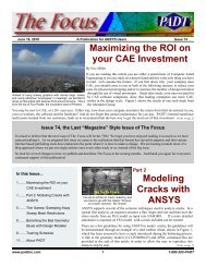
Figure 1: Simple Model<br />
entire table (i.e. your film coefficient values<br />
for a transient thermal analysis). The *m<br />
commands are limited in how you can modify<br />
a table. One tidbit that people seem<br />
surprised to hear is that you can use all of<br />
the *vxxx commands to modify tables<br />
(*voper, *vfun, etc.). The only issue you<br />
have to deal with is that the *vxxx commands<br />
only operate on a single column.<br />
You can get around this limitation using a<br />
*get and *do loop. Using the *get, you can<br />
pull the number of columns (note, that the<br />
value returned does not include the 0-th<br />
column in the total column count). You can<br />
then use the returned scalar as the limit in<br />
your *do loop to operate over an entire<br />
table.<br />
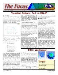
A very simple test case is shown in the<br />
Macro ROTDYN1.MAC. Use it to explore<br />
some of the topics discussed below. Figure<br />
1 shows the model.<br />
S<strong>up</strong>ported Elements<br />
After doing the homework above you will<br />
see how you can add RD simulation by<br />
calculating the Coriolis Terms [G] and adding<br />
them to your damping matrix [C] as is<br />
shown by the equation of motion that AN-<br />
SYS uses:<br />
Adding those terms for a simple pipe and<br />
mass element is not so hard and this was<br />
done years ago. The last two releases have<br />
added far more general elements that allow<br />
for much more accurate modeling, which<br />
has been a lot of work for the programmers<br />
in Pittsburgh. A summary is shown in<br />
<strong>Table</strong> 1.<br />
The CORIOLIS Command and Changing the<br />
Solver<br />
The basic step that you need to do to include<br />
the Coriolis terms in your solution is execute<br />
the CORIOLIS, Option,-,-,RefFrame<br />
command. When Option = 1, ANSYS cal-<br />
(Cont. on Pg. 2.)<br />
<strong>Table</strong> <strong>Operations</strong> - A <strong>Lost</strong> <strong>Art</strong><br />
Using this method, you can further improve<br />
it by having your script only operate on<br />
certain columns, rather than the entire table.<br />
If you look closer at the *v commands, you<br />
can also add controls on which rows you<br />
want to operate on. The *v commands<br />
require you to specify the starting point for<br />
the operation, and then they<br />
Contents<br />
(Cont. on Pg. 5.)<br />
<strong>Rotor</strong> <strong>Dynamics</strong>...............................1<br />
<strong>Table</strong> <strong>Operations</strong> ............................1<br />
Tension/Comp Mat Props...............5<br />
Awesome APDL..............................6<br />
Advertising ......................................7<br />
www.padtinc.com 1 1-800-293-<strong>PADT</strong>
February 23, 2007 The Focus Issue 55<br />
(<strong>Rotor</strong>dynamics, Cont.)<br />
BEAM4<br />
PIPE16<br />
MASS21<br />
SOLID45<br />
SOLID95<br />
ELEMENT<br />
SHELL181<br />
PLANE182<br />
PLANE183<br />
SOLID185<br />
SOLID186<br />
SOLID187<br />
BEAM188<br />
BEAM189<br />
SOLSH190<br />
SHELL281<br />
You can capture this in ANSYS with a<br />
spring-damper element like COMBI14,<br />
which has been around for a while, or with<br />
the newer COMBI214 which was purpose<br />
built for modeling bearings in rotor dynamics.<br />
The 214 allows you to specify stiffness<br />
and damping ratio at 0, 45, 90 and 135 if<br />
you have non-symmetric bearings (just 0 if<br />
it is symmetric) and you can give ANSYS a<br />
table for those values. What this means is<br />
that you can make the con-<br />
Stationary<br />
Reference<br />
Frame<br />
Rotating<br />
Reference<br />
Frame<br />
<strong>Table</strong> 1: Summary of <strong>Rotor</strong> <strong>Dynamics</strong> Elements<br />
at 11.0<br />
culates the Coriolis terms for the appropriate<br />
elements. You then use the RefFrame<br />
argument to specify if you are doing a stationary<br />
reference frame (see below).<br />
The only down side of applying the Coriolis<br />
terms in the damping matrix is that damping<br />
matrices are non-symetric, and therefore<br />
require a non-symmetric eigenvalue solver<br />
for eigenvalue problems. Fortunately, the<br />
QRDAMP solver has had a lot of work done<br />
on it and it is very fast and robust at 11.0.<br />
So don’t forget the MODOPT,<br />
QRDAMP,,,ON to activate the solver and<br />
tell it to do a complex solution.<br />
Typical RD Simulations<br />
You can include the Coriolis terms in AN-<br />
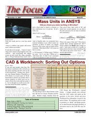
Figure 2: Campbell Diagram for Simple Model<br />
TYPE of STATIC, MODAL, HARMONIC<br />
and TRANS, and HARMONIC and<br />
TRANS include full and modal s<strong>up</strong>erposition<br />
solutions. The most common type of<br />
RD simulation is a natural frequency simulation<br />
(modal) analysis. When the geometry<br />
is not spinning a standard modal analysis<br />
works just fine, but when there is spinning<br />
the Coriolis term adds those non-symmetric<br />
terms that introduce forces to the system,<br />
which cause the natural frequencies to split<br />
and shift <strong>up</strong> and down (see Bearings and<br />
Damping along with Whirling below and<br />
the “Practical Review” article.) So in order<br />
to design a rotating machine, you need to<br />
know where your natural frequencies are at<br />
a given speed, usually so you can avoid a<br />
nasty excitation at some common speed. As<br />
is shown in example one, you get a feel for<br />
how speed effects frequency by running at<br />
0 RPM and then several speeds <strong>up</strong> to the<br />
maximum rotational velocity that the system<br />
will see.<br />
The next most common simulation is a harmonic<br />
analysis. Here you sweep through a<br />
range of excitations where the excitation<br />
frequency is also applied as the rotating<br />
frequency. Again, the Coriolis terms shift<br />
the frequencies, and damping plays a bigger<br />
role, making such a simulation very valuable.<br />
If your excitation is different from your<br />
rotating frequency, you can use the SYN-<br />
CHRO command to scale it <strong>up</strong> or down.<br />
Finally, many people want to know the<br />
loads that are exerted on structures, joints<br />
and bearings when a rotating structure rotates<br />
(think jet engine spinning on a wing<br />
then the plane turns). This can be done as a<br />
static (apply IC commands to specify velocities)<br />
or transient dynamic<br />
simulation where<br />
the Coriolis effects are<br />
included.<br />
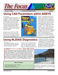
Campbell Diagrams<br />
The primary post processing<br />
tool for people<br />
doing RD work is the<br />
Campbell Diagram.<br />
This workhorse graph<br />
for turbomachinary designers<br />
is also very<br />
powerful when applied<br />
to RD. The big difference<br />
from a traditional<br />
Campbell Diagram is<br />
that you can see the<br />
modes split because of<br />
whirling. Sometimes, the deviation can be<br />
significant and you may end <strong>up</strong> right at an<br />
excitation frequency.<br />
Figure 2 shows the Campbell Diagram produced<br />
by ANSYS with the PLCAMP command.<br />
There is also a PRCAMP command.<br />
For simple systems these commands work<br />
great and are very quick to generate. If you<br />
have a more complex system, you may want<br />
to take the time to do a set, all to a file,<br />
massage in Excel, and make your own diagram.<br />
Stationary vs. Rotating Frames<br />
Another thing you should have learned<br />
from the above references is the difference<br />
between solving in a rotating vs. a stationary<br />
reference frame. If you are having a<br />
tough time with the difference, you may<br />
find the Wikipedia article “Rotating reference<br />
frame” useful from a math perspective.<br />
From a practical standpoint, if the parts are<br />
attached to a fixed structure, then you need<br />
to solve in the stationary frame and if it is<br />
not, use the rotating frame. A key thing to<br />
note when using the rotating reference<br />
frame is that spin softening is automatically<br />
included. This can then cause solution<br />
problems because the stiffness matrix becomes<br />
negative when the the rotational velocity<br />
is higher than the natural frequency<br />
(see equations 3-77 to 3-79 in the Theory<br />
Manual.) If you run into this problem apply<br />
a negative shift to a modal run or use large<br />
deflection for transient dynamic or static<br />
runs.<br />
Bearings, Damping and Whirling<br />
In the real world, rotating structures are<br />
attached to static structures through some<br />
sort of bearing. Bearings are not infinitely<br />
stiff, and the friction and lubricant in them<br />
introduce damping. So now you can visualize<br />
your system rotating on a set of springs,<br />
and often springs that have stiffness that<br />
varies with speed and direction. The same<br />
goes for damping.<br />
(Cont. on Pg. 3.)<br />
www.padtinc.com 2 1-800-293-<strong>PADT</strong>
February 23, 2007 The Focus Issue 55<br />
(<strong>Rotor</strong>dynamics, Cont.)<br />
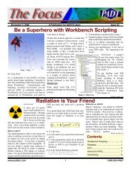
Figure 3: Whirl Model<br />
tribution dependent on other calculated values<br />
like time, speed or temperature. See the<br />
doc on the element for more information.<br />
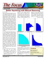
One of the improvements to the software for<br />
RD was the inclusion of the PLORB and<br />
PRORB commands in POST1 for plotting<br />
the whirling (or orbiting) of beam/mass RD<br />
models. Figure 3 shows an example for<br />
ROTDYN1.mac. In addition, you can use<br />
the ANHARM macro to create an animation<br />
of the whirl for beam/mass and solid RD<br />
models. This has been a very useful tool<br />
because some modes whirl “forward” and<br />
other “backward” The ANHARM macro is<br />
a great way to visualize this.<br />
Full 3D Models<br />
For many decades people have been doing<br />
rotor dynamics with in-house and commercial<br />
codes that used beams and masses. And<br />
for most rotor assemblies, this is still not<br />
only the most efficient, but the most accurate<br />
method. But sometimes a system does<br />
not lend itself to this type of approximation<br />
and ANSYS has provided a unique solution<br />
in the industry to address it.<br />
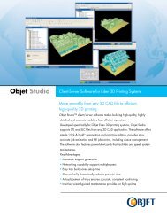
A good example is the geometry shown in<br />
Figure 4. This is an approximation of a<br />
turbo-molecular pump that <strong>PADT</strong> worked<br />
on a while ago. The design was never<br />
viable because we could never get through<br />
a critical speed do to size/bearing constraints.<br />
But one thing we found was that<br />
spin stiffening and spin softening played an<br />
important role along with bearing damping<br />
and stiffness. There is no way to model that<br />
type of geometry for rotor dynamics without<br />
using a full 3D model.<br />
ROTDYN2.MAC is a simplified sample<br />
problem with stress stiffening turned on.<br />
Figure 5 shows typical results for this geometry.<br />
Most of the examples where you would use<br />
this geometry include rotating structures<br />
where stress stiffening is important or<br />
where the axisymmetric static modes in the<br />
part may interact with whirl modes.<br />
Random RD Thoughts<br />
This article is already too long. But there<br />
are a few more key things users should<br />
know when diving into this great capability:<br />
Models in the stationary reference<br />
frame must be axisymmetric. No bladed<br />
disks!<br />
When you do Campbell Diagram<br />
plot/list or a orbit plot/list POST11 goes<br />
into a special mode and some post processing<br />
commands don’t work as expected.<br />
Always do a new SET<br />
command when you are done with<br />
Figure 4: 3D Representative TMP Model<br />
Figure 5: Mixed C<strong>up</strong> and Shaft Mode<br />
Campbell and Orbit post processing.<br />
This is especially true for the AN-<br />
HARM command. It won’t work unless<br />
you do the SET.<br />
If you have more than one rotating<br />
gro<strong>up</strong>, not a problem. Use the CMO-<br />
MEGA command to specify the rotating<br />
axis and magnitude. PLORB, AN-<br />
HARM recognize the different gro<strong>up</strong>s<br />
automatically and you can specify a<br />
gro<strong>up</strong> to plot in the Campbell diagram<br />
with PLCAMP<br />
If you are going to turn on stress stiffening,<br />
you need to tell ANSYS to not save<br />
the stress run in the results file with the<br />
CAMPBELL,ON command. Otherwise<br />
on each run in your loop that steps<br />
through speed, your result file will get<br />
overwritten.<br />
It can sometimes be tricky to constrain<br />
out the rotational degree of freedom on<br />
a stationary reference frame 3D model.<br />
A good way is to create a massless mass<br />
element, constrain its axial rotational<br />
DOF, then use RBE3’s to tie that DOF<br />
to the ends of you shafts (See<br />
ROTDYN2.MAC for an example). On<br />
beams, just constrain the rotational<br />
DOF.<br />
If you are building a beam/mass model<br />
and you want to plot results on the 3D<br />
geometry (/ESHAPE,1) then you must<br />
save the element results by setting the<br />
4 th argument in MXPAND to yes: MX-<br />
PAND, ,,,YES<br />
Animations of the whirl solutions along<br />
with the example macros can be downloaded<br />
from :<br />
ftp.padtinc.com/public/downloads/roto_dy<br />
n_focus.zip<br />
www.padtinc.com 3 1-800-293-<strong>PADT</strong>
February 23, 2007 The Focus Issue 55<br />
finish $/clear<br />
/file,rotdyn1<br />
/prep7<br />
! Define geometry params<br />
shftlen = 12<br />
shftdia = 1<br />
dskoff = shftlen*.75<br />
dskdia = 5<br />
dskthk = 1<br />
bstf = 60000 ! Brng Stiffness<br />
nmd = 20 ! Number of modes<br />
nmspn = 5 ! Number of speeds<br />
mxspn = 6000 ! Max Omega<br />
! Build model nodes<br />
n,1<br />
n,5,dskoff-(dskthk/2)<br />
n,6,dskoff+(dskthk/2)<br />
n,10,shftlen<br />
fill,1,5<br />
fill,6,10<br />
! Bearing ground nodes<br />
n,101,<br />
n,201,<br />
n,110,nx(4)<br />
n,210,nx(4)<br />
! Use 188 elements, solid<br />
et,1,188,,,2<br />
sectype,11,beam,csolid<br />
secdata,shftdia/2<br />
ROTDYN1.MAC<br />
sectyp,12,beam,csolid<br />
secdata,dskdia/2,18<br />
! Make elements<br />
et,11,14,,2<br />
et,12,14,,3<br />
r,10,bstf<br />
secnum,11<br />
type,1 $mat,1<br />
real,1<br />
e,1,2 $e,2,3<br />
e,3,4 $e,4,5<br />
e,6,7 $e,7,8<br />
e,8,9 $e,9,10<br />
secnum,12 $e,5,6<br />
type,11 $real,10<br />
e,1,101 $e,4,110<br />
type,12 $real,10<br />
e,1,201 $e,4,210<br />
! Fix axial and rotational DOF at ends<br />
d,1,ux $d,1,rotx<br />
d,4,ux $d,4,rotx<br />
! Fix Brng ground nodes<br />
d,101,all $d,201,all<br />
d,110,all $d,210,all<br />
! Plot the model<br />
/view,1,1,1,1 $/v<strong>up</strong>,1,z<br />
/eshape,1,1 $/pnum,sect,1<br />
/num,1 $eplot<br />
! Dummy mat props<br />
ex,1,10e6 $nuxy,1,.23 $dens,1,.001<br />
finish $/solu<br />
! Set<strong>up</strong> modal run<br />
antype,modal<br />
coriolis,on,,,on<br />
modopt,qrdamp,nmd,,,on<br />
! Loop on speeds<br />
*do,i,1,nmspn<br />
spn = (i-1)*(mxspn/(nmspn-1))<br />
omega,spn<br />
mxpand,nmd,,,yes<br />
solve<br />
*enddo<br />
finish<br />
/post1<br />
! Plot/List Campbell Diagrams<br />
plcamp,,1,rpm<br />
prcamp,,1,rpm<br />
! Plot orbit<br />
set,5,6<br />
plorb<br />
! Animate whirl<br />
set,5,6<br />
plnsol,u,sum<br />
anharm<br />
finish $/clear<br />
/file,rotdyn2<br />
/prep7<br />
! Set Geometry Parameters<br />
shftrad = .25<br />
shftlen = 3<br />
webthk = .5<br />
conir1 = 1.75<br />
conir2 = 1.65<br />
conor1 = 2.25<br />
conor2 = 1.75<br />
conoff = -.5<br />
stblen = 1<br />
! Set Speed and Bearing Stiffness<br />
mxspn = 10000*2*3.14159/60<br />
bstf = 20000<br />
nmd = 20 !number of modes<br />
nmspn = 5 ! Number of speeds<br />
! Build model<br />
k,1,0, $k,2,shftlen<br />
k,3,shftlen+webthk<br />
k,4,0,shftrad<br />
k,5,shftlen,shftrad<br />
k,6,shftlen+webthk,shftrad<br />
k,7,0+conoff,conir1<br />
k,8,shftlen,conir2<br />
k,9,shflen+webthk,conir2<br />
k,10,0+conoff,conor1<br />
k,12,shftlen+webthk,conor2<br />
k,13,kx(3)+stblen<br />
k,14,kx(3)+stblen,shftrad<br />
a,1,13,14,6,12,10,7,8,5,4<br />
adel,all<br />
lfill,8,9,.25 $lfill,7,8,.25<br />
lfill,3,4,.25 $lfill,4,5,.5<br />
al,all<br />
ROTDYN2.MAC<br />
et,200,200,6 !Mesh 2D Area<br />
esize,.125<br />
amesh,all<br />
et,1,185 ! Set<strong>up</strong> solid element and<br />
revolve<br />
type,1<br />
esize,,6<br />
vrotat,all,,,,,,1,2,360<br />
asel,s,loc,x,0 !Fix ends in axial DOF<br />
nsla,s,1<br />
d,all,ux<br />
cm,nfx1,node<br />
asel,s,loc,x,kx(13)<br />
nsla,s,1<br />
d,all,ux<br />
cm,nfx2,node<br />
nall<br />
et,10,214,,1,0 ! Make the Brng Element<br />
r,10,bstf,bstf<br />
! find node on shaft<br />
nn1 = node(kx(1),ky(1),kz(1))<br />
nn2 = node(kx(13),ky(13),kz(13))<br />
! Ground node<br />
n,30000,nx(nn1),ny(nn1)+.5,nz(nn1)<br />
n,30001,nx(nn2),ny(nn2)+.5,nz(nn2)<br />
n,40000,nx(nn1),ny(nn1),nz(nn1)<br />
n,40001,nx(nn2),ny(nn2),nz(nn2)<br />
type,10 $real,10 $mat,10<br />
e,nn1,30000 $e,nn2,30001<br />
d,30000,all $d,30001,all<br />
! Fake mass elements for fixing ROTX<br />
et,201,21 $r,200<br />
type,201 $real,200<br />
e,40000 $e,40001<br />
d,40000,rotx $d,40001,rotx<br />
! Tie masses to ends of shaft<br />
cmsel,s,nfx1<br />
nsel,a,,,40000<br />
rbe3,40000,rotx,all<br />
cmsel,s,nfx2<br />
nsel,a,,,40001<br />
rbe3,40001,rotx,all<br />
nall<br />
! Dummy mat props<br />
ex,1,10e6 $nuxy,1,.23<br />
dens,1,.001<br />
finish<br />
/solu<br />
coriolis,on,,,on ! Turn on RD<br />
campbell,on !tell ANSYS to save rst<br />
*do,i,1,nmspn !loop on speeds<br />
finish<br />
/solu<br />
antype,static !Prestress run<br />
pstres,on<br />
spn = (i-1)*(mxspn/(nmspn-1))<br />
omega,spn<br />
solve<br />
finish<br />
/solu<br />
antype,modal !Modal run<br />
pstres,on<br />
modopt,qrdamp,nmd,,,on<br />
mxpand,nmd<br />
solve<br />
*enddo<br />
save<br />
finish<br />
/post1<br />
/view,1,-1,1,1<br />
/v<strong>up</strong>,1,z<br />
/dist,1,2.937<br />
/focus,1,1.25,.43,0<br />
set,nmspn,3<br />
plnsol,u,sum,1 ! Plot mode shape<br />
anharm ! Animate whirling<br />
www.padtinc.com 4 1-800-293-<strong>PADT</strong>
February 23, 2007 The Focus Issue 55<br />
(<strong>Table</strong>, cont.)<br />
The fix is to copy Doug<strong>Table</strong> to another<br />
want you to modify the first 3 rows or your temporary table (created using *dim). *voper,Doug<strong>Table</strong>(1,i),d_<br />
table, set your starting point to be the fourth<br />
row (i.e. *voper,tablename(4,i),... where i is<br />
the column number).<br />
Then, simply set the “stored to location”<br />
parameter of the *voper command to be<br />
Doug<strong>Table</strong>, as shown below:<br />
temp(1,i),mult,2<br />
This built-in looping of the *v commands<br />
can cause problems if you want to apply<br />
different operations to different rows of<br />
your table. For example, say you wanted to<br />
modify an existing table that is graphically<br />
shown as Doug<strong>Table</strong>.<br />
By: Rod Scholl<br />
*dim,d_temp,table,5,5<br />
*mfun,d_temp(0,0),copy,D<br />
oug<strong>Table</strong>(0,0)<br />
*get,d_column,parm,'doug<br />
table',dim,<br />
*do,i,1,d_column<br />
*voper,Doug<strong>Table</strong>(3,i),d_<br />
temp(3,i),sub,10<br />
*enddo<br />
A little practice and creativity can help you<br />
to further expand on this macro. Ultimately,<br />
you can move your get to the front of the<br />
macro to pull the x (row) and y (columns)<br />
dimensions of your table and use those to<br />
define your temporary table. To really<br />
show off to your fellow analysts (because if<br />
your spouse isn't an engineer, they definitely<br />
won't appreciate it – just ask my wife),<br />
you can use Jeff Strain's “*Varying your<br />
*Vwrite” (July 2004) to make your script<br />
more flexible in handling table names and<br />
different scaling operations.<br />
Unequal Tension/Compression Mat. Prop's<br />
Back in release 9.0, some significant improvements<br />
were made to the Cast-Iron<br />
material model. The most remarkable feature<br />
of this material model is the ability to<br />
implement different tensile vs. compressive<br />
plasticity curves. However, this capability<br />
can be expanded (with a little effort) to<br />
model a different compressive vs. tensile<br />
modulus by tweaking the plasticity curve.<br />
The expected usage of the cast-iron input<br />
looks like the following:<br />
TB,UNIAXIAL,1,1,3 ,COMPRESSION<br />
TBTEMP,10<br />
TBPT,,0.203E-02,0.300E+05<br />
TBPT,,0.500E-02,0.500E+05<br />
TBPT,,…<br />
To extend this power further, one can essentially<br />
model materials with unequal tensile<br />
and compressive modulus. Of course the<br />
problem is non-linear, so there is a penalty<br />
here, but it is a fairly cheap resolution to the<br />
case where the moduli are unequal.<br />
By making the linear elastic portion of the<br />
material model negligibly small, one can<br />
accomplish two separate moduli curves.<br />
higher, the corresponding modulus is applied.<br />
This, of course requires a non-linear<br />
solution, which may or may not be an added<br />
expense depending if other non-lienarities<br />
are already present at their relative convergence<br />
rate. Test cases on a simple cube<br />
showed very quick convergence with this<br />
model, with 3 iterations required when<br />
forced to a single substep via<br />
(Cont. on Pg. 6.)<br />
A Typical input looks like:<br />
TB,CAST,1,,,ISOTROPIC<br />
TBDATA,1,0.04<br />
TB,UNIAXIAL,1,1,5,TENSION<br />
TBTEMP,10<br />
TBPT,,0.550E-03,0.813E+04<br />
TBPT,,0.100E-02,0.131E+05<br />
TBPT,,…<br />
Thus <strong>up</strong> to some small value of strain, such<br />
as 1e-6 in/in the compression and tension<br />
will use the higher modulus. But for strains<br />
www.padtinc.com 5 1-800-293-<strong>PADT</strong>
February 23, 2007 The Focus Issue 55<br />
Awesome APDL: Customizing Animation Macros<br />
By Rod Scholl<br />
Several times now I’ve posted emails<br />
looking for some special graphics<br />
script, such as a custom animation, and<br />
each time someone has to remind me<br />
that I can edit the ANSYS scripts themselves.<br />
Not every command is a script,<br />
but the animation actions are. There is<br />
a collection of them in the installation<br />
directory. ANMODE.MAC is a good<br />
example for mode shapes.<br />
One thing I’ve never liked is that it<br />
only shows the 1 st half of the modal<br />
cycle in the .avi file. I want it to show<br />
the expansion AND contraction cycle.<br />
That way I can put the created .avi file<br />
loop-play in a media player and stare<br />
ad infintum at the gracefully moving<br />
image. Ahhh, peace at last… Of<br />
course this is how the ANSYS gui displays<br />
it, but I wanted to be able to<br />
easily send these mesmerizing videos<br />
to the customer.<br />
It was a simple change to make the 2 nd<br />
half of the capture loop backward. The<br />
first part of the code to the right shows<br />
the original APDL chunk that sets the<br />
distortion scale factor (DSC) and does<br />
the replot. In the second half, an *if<br />
statement is added that scales forward<br />
on the first half and backwards on the<br />
second.<br />
It usually only takes a few minutes of<br />
poking around, making changes, and<br />
seeing what happens to figure out some<br />
minor modifications. So take advantage<br />
of these “open source” goodies<br />
from ANSYS Inc!<br />
!--- Original Script -----<br />
!COM *****************<br />
!COM CAPTURE FOR JavaScript<br />
!COM *****************<br />
~tcl,'ansys::report::animImage'<br />
*ELSE ! } {<br />
/REPLOT<br />
*ENDIF ! }<br />
_DSC=_DSC-_DDD<br />
*ENDDO<br />
!--- Modified Script -----<br />
!COM *****************<br />
!COM CAPTURE FOR JavaScript<br />
!COM *****************<br />
~tcl,'ansys::report::animImage'<br />
*ELSE ! } {<br />
/REPLOT<br />
*ENDIF ! }<br />
*if,_i,lt,AR11/2,then<br />
_DSC=_DSC-_DDD*2<br />
*else<br />
_DSC=_DSC+_DDD*2<br />
*endif<br />
*ENDDO<br />
(tension/compression, cont.)<br />
NSUBST,1,1,1. This method shouldn’t be<br />
a path-dependent (irreversible) solution if<br />
you are simulating linear modulus with this<br />
method.<br />
And finally, one last trick (which took quite<br />
some time to sort out) is that the curve can’t<br />
quite be linear… it is allowed in KINH for<br />
example, but not in the case of cast-iron.<br />
Thus you must make the curve minimally<br />
decreasing at each point.<br />
The whole script can be downloaded here,<br />
but the interesting part is as follows:<br />
MPTEMP,,,,,,,,<br />
MPTEMP,1,0<br />
MPDATA,EX,1,,10e6<br />
MPDATA,PRXY,1,,.3<br />
TB,CAST,1,,,ISOTROPIC<br />
TBDATA,1,0.04<br />
TB,UNIAXIAL,1,1,3,TENSION<br />
TBTEMP,10<br />
TBPT,,1e-6,10e6*1e-6<br />
!NOTE the -1 for slightly<br />
! decreasing slope<br />
tbpt,,1e-5,10e6*1e-5-1<br />
!NOTE the -2 for slightly<br />
! decreasing slope<br />
tbpt,,1e-1,10e6*1e-1-2<br />
TB,UNIAXIAL,1,1,3,COMPRESSION<br />
TBTEMP,10<br />
TBPT,,1e-6,10e6*1e-6<br />
!NOTE the -1 for slightly<br />
! decreasing slope<br />
tbpt,,1e-5,5e6*1e-5-1<br />
!NOTE the -2 for slightly<br />
! decreasing slope<br />
TBPT,,1e-1,5e6*1e-1-2<br />
nsubst,1,1,1<br />
solve<br />
Upcoming Training Classes<br />
Month Start End # Title Location<br />
Feb '07 26-Feb 28-Feb 104 ANSYS Workbench Sim - Intro Tempe, AZ<br />
Mar '07 8-Mar 9-Mar 105 ANSYS WB NL Structural Tempe, AZ<br />
12-Mar 13-Mar 203 <strong>Dynamics</strong> LV., NV<br />
19-Mar 20-Mar 501 ANSYS/LS-DYNA Tempe, AZ<br />
28-Mar 30-Mar 902 Multiphysics Sim for MEMS Tempe, AZ<br />
Apr '07 2-Apr 4-Apr 101 Introduction to ANSYS, Part I Tempe, AZ<br />
5-Apr 6-Apr 107 ANSYS WB DesignModeler Tempe, AZ<br />
9-Apr 11-Apr 401 Low Freq. Electromagnetics Tempe, AZ<br />
12-Apr 13-Apr 604 Introduction to CFX Tempe, AZ<br />
16-Apr 18-Apr 201 Basic Structural Nonlinearities Tempe, AZ<br />
18-Apr 19-Apr 204 Adv. Contact and Fasteners Tempe, AZ<br />
25-Apr 27-Apr 152 ICEM CFD/AI*Environment Tempe, AZ<br />
May '07 2-May 4-May 104 ANSYS WB Simulation - Intro LV, NV<br />
7-May 8-May 100 Engineering with FEA Tempe, AZ<br />
Links<br />
News<br />
ANSYS, Inc. Is doing some great regional user gro<strong>up</strong><br />
meetings in North America. These are highly technical<br />
and well attended: www.converge.ansys.com<br />
Feel the need for making high quality graphs in batch<br />
mode outside of ANSYS. GNUPlot has been around for<br />
years and keeps getting better:<br />
www.gn<strong>up</strong>lot.info<br />
- ANSYS 11.0 Products Released<br />
Visit www.ansys.com for details in the near<br />
future. <strong>PADT</strong> will cover the 11.0 release<br />
heavily at our on-line seminar and in future<br />
issues of The Focus<br />
The Focus is a periodic publication of Phoenix Analysis & Design Technologies (<strong>PADT</strong>).<br />
Its goal is to educate and entertain the worldwide ANSYS user community. More information<br />
on this publication can be found at: http://www.padtinc.com/epubs/focus/about<br />
www.padtinc.com 6 1-800-293-<strong>PADT</strong>
February 23, 2007 The Focus Issue 55<br />
The Shameless<br />
Advertising Page<br />
The 2007 <strong>PADT</strong> CAE Wall Calenders are here!<br />
Do You Read the Focus<br />
and Find it Useful?<br />
Does Your Company<br />
Outsource their RP Jobs?<br />
One year, at a glance. And this year, no froofroo<br />
pastel colors!<br />
Visit:<br />
www.padtinc.com/docs/lit/padt_2007_1.pdf<br />
to download your copy before your wall fills<br />
<strong>up</strong>!<br />
Have you Considered<br />
<strong>PADT</strong> as your<br />
RP Source?<br />
<strong>PADT</strong> is a Leader<br />
in High Quality<br />
SLS, SLA, FDM and<br />
Injection Molding<br />
Let us Quote your<br />
Next RP Job<br />
rp@padtinc.com<br />
CFD Simulation Services<br />
<strong>PADT</strong> Knows Flow<br />
Outsource your next CFD Job to the <strong>PADT</strong>’s CFD Experts<br />
www.padtinc.com 1-800-293-<strong>PADT</strong><br />
www.padtinc.com 7 1-800-293-<strong>PADT</strong>