Mass Units in ANSYS CAD & Workbench: Sorting Out Options - PADT
Mass Units in ANSYS CAD & Workbench: Sorting Out Options - PADT
Mass Units in ANSYS CAD & Workbench: Sorting Out Options - PADT

Create successful ePaper yourself
Turn your PDF publications into a flip-book with our unique Google optimized e-Paper software.
December 13, 2007 The Focus Issue 61<br />
December 13, 2007 A Publication for <strong>ANSYS</strong> Users Issue 61<br />
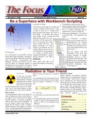
By Rod Scholl<br />
Well this could just be a one l<strong>in</strong>e article<br />
right?<br />
“Ansys is unitless, just ensure self-consistency<br />
with<strong>in</strong> your model.”<br />
If only that were enough… I know it wasn’t<br />
when I first started us<strong>in</strong>g English units with<br />
<strong>ANSYS</strong> – and occasionally this subject<br />
comes up and words like slugs, poundals,<br />
lbm vs. lbf get bantered about, and I wish I<br />
By Eric Miller<br />
If you ask most people what they like<br />
best about workbench, 30% will tell you<br />
the robust mesh<strong>in</strong>g and 30% will say the<br />
<strong>CAD</strong> connections * . Gett<strong>in</strong>g your geometry<br />
<strong>in</strong>to Design Modeler, Simulation or<br />
CFX Mesh is so much easier <strong>in</strong> <strong>Workbench</strong><br />
than <strong>in</strong> almost any product that is<br />
always surprises us when users are unaware<br />
of how this works and how great it<br />
is. So we thought we would cover a few<br />
key facts about this killer capability. †<br />
*<br />
These percentages fall <strong>in</strong> the SWAG category,<br />
but are probably pretty close. What about the<br />
other 40%, they fall <strong>in</strong> that “other” category<br />
and mention stuff like automatic report, the<br />
model tree, ease of use, fast graphics, etc…<br />
† This article was orig<strong>in</strong>ally published <strong>in</strong> the<br />
September ‘07 issue of the SWAU Report. It was<br />
so popular that we decided to repr<strong>in</strong>t it here.<br />
<strong>Mass</strong> <strong>Units</strong> <strong>in</strong> <strong>ANSYS</strong><br />
had a cheat sheet to hand to someone so<br />
they could pour over it <strong>in</strong> private. So let’s<br />
make one.<br />
With F=M*A we get:<br />
Did you know you were work<strong>in</strong>g <strong>in</strong> Sl<strong>in</strong>ches?<br />
Force<br />
<strong>Mass</strong> =<br />
Acceleration<br />
And <strong>in</strong> English units, we commonly have<br />
material modulus <strong>in</strong> psi, which means our<br />
geometry is likely <strong>in</strong> <strong>in</strong>ches, our outputs<br />
stresses will be <strong>in</strong> psi, and our loads will be<br />
<strong>in</strong> pounds. What k<strong>in</strong>d of lbs? Lbf. (more on<br />
that to come).<br />
A 170 lb person’s 170 lbm exerts 170 lbf on<br />
the scale. So it’s not that 170lbm isn’t a<br />
valid mass unit, it’s that it isn’t consistent<br />
with an acceleration <strong>in</strong> units of <strong>in</strong>ch/sec 2 .<br />
Supported Formats<br />
The first th<strong>in</strong>g to know about formats is that<br />
they fall <strong>in</strong>to two classes: Readers and PlugIns.<br />
Readers simply translate from the<br />
Thus given these <strong>in</strong>put units of lbf, and<br />
<strong>in</strong>ches per second squared, we can derive<br />
the units necessary for our mass to ma<strong>in</strong>ta<strong>in</strong><br />
unit consistency:<br />
What is the name of this unit? This elusive<br />
“pound force second squared per <strong>in</strong>ch”?<br />
NASA called it the Sl<strong>in</strong>ch, (aka a mug or a<br />
snail * ) And come to th<strong>in</strong>k of it, wouldn’t a<br />
better article title have been someth<strong>in</strong>g like<br />
“The Sl<strong>in</strong>ch that Stole Christ’mass” – ahh<br />
missed opportunities…<br />
(Cont. on pg. 2)<br />
*<br />
Surpris<strong>in</strong>gly there is not much <strong>in</strong>formation on<br />
the Internet about the sl<strong>in</strong>ch. The best l<strong>in</strong>k<br />
can be found at:<br />
www.unc.edu/~rowlett/units/dictS.html<br />
<strong>CAD</strong> & <strong>Workbench</strong>: Sort<strong>in</strong>g <strong>Out</strong> <strong>Options</strong><br />
CATIA V5 (Capri Gateway) Plug<strong>in</strong> Yes<br />
Table of Contents<br />
<strong>Mass</strong> <strong>Units</strong> <strong>in</strong> <strong>ANSYS</strong> -----------------------------------------------------------------1<br />
<strong>CAD</strong> & <strong>Workbench</strong>: Sort<strong>in</strong>g <strong>Out</strong> <strong>Options</strong> ----------------------------------------1<br />
Efficiency with Instanc<strong>in</strong>g -------------------------------------------------------------3<br />
F<strong>in</strong>d<strong>in</strong>g Close Areas: Us<strong>in</strong>g ACON.EXE -----------------------------------------4<br />
Awesome APDL: Pars<strong>in</strong>g a Text File----------------------------------------------5<br />
[ lbf ] [ lbf ]*[sec]<br />
[ <strong>Mass</strong> ] =<br />
=<br />
2<br />
[ <strong>in</strong>ch /sec ] <strong>in</strong>ch<br />
Type Solids Surfaces Curves Attributes Names Materials<br />
DesignModeler PlugIn Yes Yes Yes Yes Yes<br />
Inventor PlugIn Yes Yes Yes Yes<br />
Mechanical Desktop PlugIn Yes Yes Yes<br />
OneSpace Designer PlugIn Yes Yes<br />
Pro/ENGINEER PlugIn Yes Yes Yes Yes Yes<br />
Solid Edge PlugIn Yes Yes Yes Yes<br />
SolidWorks PlugIn Yes Yes Yes Yes<br />
Unigraphics PlugIn Yes Yes Yes Yes Yes<br />
ACIS Reader Yes Yes<br />
CATIA V4/V5 Reader Yes Yes<br />
IGES Reader Yes Yes<br />
Parasolid Reader Yes Yes<br />
STEP Reader Yes Yes<br />
<strong>CAD</strong> format <strong>in</strong>to <strong>Workbench</strong>’s <strong>in</strong>ternal<br />
format. A plug<strong>in</strong> actually uses software<br />
from the <strong>CAD</strong> vendor and opens up the<br />
geometry <strong>in</strong> the native format and gives<br />
<strong>Workbench</strong> the <strong>in</strong>formation it needs <strong>in</strong> the<br />
native format. We sometimes refer to reader<br />
geometry as “dumb” and plug<strong>in</strong> geometry<br />
as smart because the plug<strong>in</strong> geometry is<br />
associative back to the <strong>CAD</strong> files (see below).<br />
(Cont. on pg. 2)<br />
www.padt<strong>in</strong>c.com 1 1-800-293-<strong>PADT</strong><br />
2
December 13, 2007 The Focus Issue 61<br />
(<strong>Units</strong>, cont...)<br />
So how do we convert our 170lb person to The Poundal Unit of Force<br />
A Worse Unit System<br />
our desired units of sl<strong>in</strong>ches? 170 lbs is also 1 poundal = 1lbm*1ft/sec 2<br />
If you went ahead and used the mass <strong>in</strong><br />
written 170 lbm. Both these terms assume<br />
lbm and the force <strong>in</strong> lbf… acceleration<br />
earth’s gravitational field, and thus 32.17 If we enter our mass <strong>in</strong> lbm, and our<br />
would have to be <strong>in</strong> g’s! And if acceleration<br />
is <strong>in</strong> g’s and we leave time as<br />
ft/sec^2 or 386.09 <strong>in</strong>/sec^2.<br />
lengths <strong>in</strong> feet, we could <strong>in</strong>terpret our<br />
forces <strong>in</strong> poundals:<br />
1lbf = 1lbm*1g<br />
seconds, then what would your length<br />
2<br />
1lbf<br />
* sec 1 ft units be for consistency? It would be :<br />
1 g = 386.09 <strong>in</strong>/sec^2<br />
2<br />
1lbf<br />
1lbf<br />
1lbf<br />
* sec<br />
1lbm<br />
= =<br />
=<br />
1g<br />
<strong>in</strong>ch 386.09<strong>in</strong>ch<br />
386.09<br />
2<br />
sec<br />
So we divide the mass <strong>in</strong> “pounds” by<br />
386.09 and get our mass <strong>in</strong> sl<strong>in</strong>ches. Density:<br />
Similarly one divides the density by 386.09<br />
to keep unit consistency. If you look at<br />
many <strong>ANSYS</strong> APDL macros that def<strong>in</strong>e<br />
material properties, you will often see the<br />
tell-tale den=den/(32.17*12). I would call<br />
this a “Sl<strong>in</strong>ch per cubic <strong>in</strong>ch” because its<br />
just pla<strong>in</strong> fun to say…<br />
Density:<br />
lbm<br />
<strong>in</strong>ch<br />
3<br />
2<br />
1lbf<br />
* sec<br />
= 386.04<strong>in</strong>ch<br />
<strong>in</strong>ch<br />
3<br />
2<br />
1lbf<br />
* sec<br />
=<br />
386.09 * <strong>in</strong>ch<br />
4<br />
1poundal = *<br />
386.09<strong>in</strong>ch<br />
sec<br />
1lbf<br />
* ft 1lbf<br />
= =<br />
386.09<strong>in</strong>ch<br />
32.17<br />
Thus if we employ the poundal we can<br />
use the lbm unit, and feet for length…<br />
yet now our modulus and stress are <strong>in</strong><br />
poundals/feet 2 .<br />
Why Not Slugs<br />
<strong>Units</strong> of slugs are close to what one<br />
would want... But a slug uses acceleration<br />
<strong>in</strong> ft/sec 2 not <strong>in</strong>/sec 2 - this shakes<br />
down like such:<br />
ft<br />
1lbf = 1slug<br />
*1<br />
sec<br />
With some manipulation one can see<br />
that:<br />
lbf * sec<br />
1 slug =<br />
foot<br />
Which makes it a factor of 12 off from<br />
the Sl<strong>in</strong>ch. Of course hav<strong>in</strong>g geometry<br />
<strong>in</strong> feet would be pretty well accepted,<br />
but this also means your modulus and<br />
stress are <strong>in</strong> lbf/ft 2 , a k<strong>in</strong>da non-standard<br />
unit.<br />
2<br />
2<br />
2<br />
… and modulus/stress would have to<br />
be <strong>in</strong>:<br />
It’ll work… but expect some rotten<br />
fruit dur<strong>in</strong>g that design review.<br />
F = M*A<br />
2<br />
g *sec<br />
g<br />
2<br />
lbf<br />
*sec<br />
Metric Is Easy<br />
Force is <strong>in</strong> units of Newtons, or:<br />
This goes nicely with mass be<strong>in</strong>g <strong>in</strong> kg<br />
and acceleration be<strong>in</strong>g <strong>in</strong> m/s 2<br />
4<br />
[ kg]*[<br />
m]<br />
[ s]<br />
2<br />
(<strong>CAD</strong> Import, cont...)<br />
The table above lists the formats supported<br />
by <strong>Workbench</strong> at V11. It also gives a brief<br />
summary of what does and does not come<br />
over from the geometry file <strong>in</strong>to Simulation.<br />
Pretty much all types of geometry come <strong>in</strong>to<br />
DesignModeler, so if you need surfaces or<br />
curves from an unsupported format, go<br />
through DM. Attributes and Names are important<br />
because these are pieces of <strong>in</strong>formation<br />
attached to geometry, like loads from a<br />
motion simulation or names on entities that<br />
can be used to make your simulation job<br />
much easier.<br />
How it Works<br />
The readers work <strong>in</strong> a fairly simple way.<br />
They take the geometry file and parse<br />
through the description of the entities and<br />
topology (how th<strong>in</strong>gs are connected) and<br />
build a geometric model <strong>in</strong> Simulation or<br />
DM. For the non-<strong>CAD</strong> formats (IGES,<br />
STEP, etc…) it often converts to the Parasolid<br />
format first, then to the <strong>Workbench</strong><br />
format, so don’t be surprised if you see<br />
someth<strong>in</strong>g about Parasolids dur<strong>in</strong>g import<br />
when you don’t have a parasolid file.<br />
The PlugIn’s are bit more complicated, but<br />
deliver a lot more power. What the PlugIn’s<br />
do is actually start up the <strong>CAD</strong> package that<br />
the native file comes from <strong>in</strong> a batch mode.<br />
So you need to have the <strong>CAD</strong> tool loaded on<br />
your mach<strong>in</strong>e and you need a license for the<br />
<strong>CAD</strong> tool for th<strong>in</strong>gs to work right. If you<br />
have your file already open <strong>in</strong> your <strong>CAD</strong><br />
tool, it will just use that session.<br />
If you are br<strong>in</strong>g<strong>in</strong>g <strong>in</strong> the file for the first<br />
time, it builds the geometry and topology<br />
and stores any parameters that you have<br />
asked to be transferred (this is done by<br />
specify a prefix on the parameter names) <strong>in</strong><br />
(Cont. on pg. 3)<br />
www.padt<strong>in</strong>c.com 2 1-800-293-<strong>PADT</strong>
December 13, 2007 The Focus Issue 61<br />
the parameter manager. If you are do<strong>in</strong>g an<br />
system. But even if it isn’t 100%, most of<br />
update, it can be much faster s<strong>in</strong>ce it is just<br />
the model updates and you may need to<br />
updat<strong>in</strong>g geometry, topology and parameters.<br />
redo a few loads and BC’s.<br />
One quick h<strong>in</strong>t: Set your options <strong>in</strong> <strong>Workbench</strong><br />
to release the <strong>CAD</strong> license when you<br />
are done. If you don’t do this, you will hold<br />
on to your <strong>CAD</strong> seat even if <strong>Workbench</strong> is<br />
not us<strong>in</strong>g it.<br />
Bi-Directional Associativity<br />
The big deal with us<strong>in</strong>g PlugIn’s is the<br />
bi-directional associativety that it allows. If<br />
By Eric Miller<br />
Did you know that <strong>Workbench</strong> takes advantage<br />
of geometry <strong>in</strong>stanc<strong>in</strong>g? Are you even<br />
aware of what <strong>in</strong>stanc<strong>in</strong>g is? I didn’t and<br />
wasn’t until I sent an e-mail <strong>in</strong> to <strong>ANSYS</strong>,<br />
Inc. ask<strong>in</strong>g about add<strong>in</strong>g mesh copy<strong>in</strong>g, and<br />
they said they are work<strong>in</strong>g on it but <strong>in</strong> most<br />
cases, <strong>in</strong>stanc<strong>in</strong>g works even better for what<br />
you want. “Oh yea, of course” I said, then<br />
quickly tried to figure out what the heck<br />
they were talk<strong>in</strong>g about. A little research<br />
showed a useful set of features that has been<br />
there <strong>in</strong> V11 without much notice.<br />
you change a geometry parameter either <strong>in</strong><br />
<strong>Workbench</strong> or <strong>in</strong> the <strong>CAD</strong> system itself,<br />
you can ask for an update and the workbench<br />
model will update the geometry - and<br />
this is the big deal - any mesh, loads and<br />
boundary conditions that you assigned to<br />
the geometry. This can literally save days<br />
of remesh<strong>in</strong>g.<br />
If you make a topology change, that is add<br />
a new surface or delete a surface, th<strong>in</strong>gs<br />
may not update 100%. That depends on the<br />
magnitude of the change and the <strong>CAD</strong><br />
Instanc<strong>in</strong>g<br />
Instanc<strong>in</strong>g is a term from the <strong>CAD</strong> world.<br />
It refers to how an assembly treats a part<br />
that is already <strong>in</strong> the assembly. It can read<br />
<strong>in</strong> and store all the surfaces/edges/vertices<br />
for that part or it can just po<strong>in</strong>t to the orig<strong>in</strong>al<br />
part and apply a transformation. This<br />
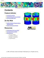
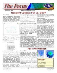
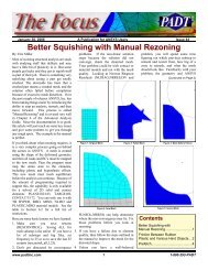
saves memory and disk space. If you look<br />
at the flexure <strong>in</strong> Figure 1 you see seven<br />
volumes made of two parts: two bases on<br />
the top and bottom and 5 flexure spr<strong>in</strong>gs<br />
<strong>in</strong>-between. I modeled these <strong>in</strong> SolidEdge,<br />
but most <strong>CAD</strong> systems display an <strong>in</strong>stance<br />
<strong>in</strong> the same way; they append some sort of<br />
number to the part name <strong>in</strong> the assembly<br />
tree (Figure 2). Note that even though the<br />
base1 parts are placed by hand and the<br />
flexures use a patterned feature, they both<br />
show up as the same part with multiple<br />
copies.<br />
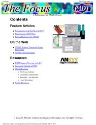
Once you import your part <strong>in</strong>to simulation,<br />
you will see the <strong>in</strong>stanc<strong>in</strong>g <strong>in</strong> there as well,<br />
and it shows up as shown <strong>in</strong> Figure 3. This<br />
works for all of the supported <strong>CAD</strong> packages<br />
but not with the “dumb” geometry files<br />
like ACIS, SAT, IGES and STEP, because<br />
As you can imag<strong>in</strong>e, this makes “what-if”,<br />
optimization and probabilistic studies very<br />
easy.<br />
Try a PlugIn Today<br />
So, if you are us<strong>in</strong>g <strong>ANSYS</strong> or read<strong>in</strong>g<br />
dumb geometry <strong>in</strong>to <strong>Workbench</strong> now, give<br />
your salesperson a call and ask for a temp<br />
key on a PlugIn for your <strong>CAD</strong> tool. Give it<br />
a shot, it will pay for itself very quickly.<br />
Efficiency with Instanc<strong>in</strong>g<br />
they do not support <strong>in</strong>stanc<strong>in</strong>g. For the<br />
same reason, you can not use this feature<br />
with DesignModeler, although development<br />
is look<strong>in</strong>g <strong>in</strong>to add<strong>in</strong>g support.<br />
Leverag<strong>in</strong>g Instances<br />
Once you have an assembly with repeated<br />
parts <strong>in</strong> <strong>Workbench</strong> Simulation, you can<br />
start to take advantage of it without any<br />
special sett<strong>in</strong>gs or commands. It is completely<br />
automatic. The first and most important<br />
advantage is that the mesher will<br />
automatically recognize that the parts are<br />
copies and only mesh the first <strong>in</strong>stance, then<br />
copy the mesh for the rema<strong>in</strong>der. This not<br />
only saves time, as <strong>in</strong> this example where<br />
the mesher only had to mesh two parts<br />
<strong>in</strong>stead of seven, but it also gives an identical<br />
mesh on each part. If you actually read<br />
the little dialog box that shows progress<br />
dur<strong>in</strong>g mesh<strong>in</strong>g, you will notice that it only<br />
meshes two parts.<br />
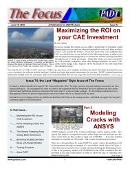
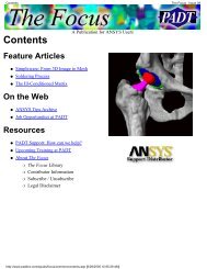
We picked this flexure model as an example<br />
because this geometry is very sensitive to<br />
mesh variation between pillars. Each mesh<br />
must be identical for the model to perform<br />
(Cont. on pg. 4)<br />
Fig. 1: <strong>CAD</strong> Geometry Fig. 2: <strong>CAD</strong> Model Tree Fig. 3: Model <strong>in</strong> Simulation with Instances<br />
www.padt<strong>in</strong>c.com 3 1-800-293-<strong>PADT</strong>
December 13, 2007 The Focus Issue 61<br />
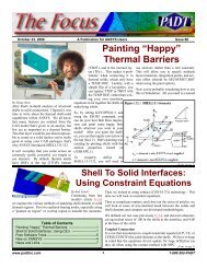
properly, and as you can see <strong>in</strong> Figure 4,<br />
each has an identical mesh.<br />
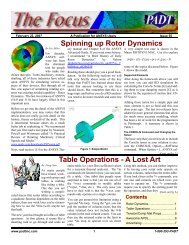
The second place where you can take advantage<br />
of <strong>in</strong>stanc<strong>in</strong>g is with a Beta feature<br />
under Extended Selection (to turn on Beta<br />
features go to Tools-><strong>Options</strong>->Common<br />
Sett<strong>in</strong>gs->User Interface->Menus/Toolbars<br />
and set “Show Beta <strong>Options</strong>” to “Yes”). If<br />
you select a vertex/edge/surface on a part<br />
that is <strong>in</strong>volved <strong>in</strong> an <strong>in</strong>stance, you can<br />
choose the “Extend to Instances” option and<br />
it will select the same feature on every<br />
<strong>in</strong>stance. This is a huge time saver if you<br />
want to apply the same load to each part, or<br />
<strong>in</strong>volve the same surface on each part <strong>in</strong> a<br />
contact. Figure 5 shows an example where<br />
one of the faces on a flexure can be chosen<br />
on each part with only two clicks: pick the<br />
part, pick “Extend to Instance.”<br />
Observations<br />
This simple little capability rem<strong>in</strong>ded me of<br />
many important th<strong>in</strong>gs. First off, there is a<br />
lot of stuff <strong>in</strong> <strong>Workbench</strong> that I am unaware<br />
of (embarrass<strong>in</strong>g!). Even though I read the<br />
release notes and even teach update sem<strong>in</strong>ars,<br />
there is always someth<strong>in</strong>g I miss or do<br />
not remember. Second, the <strong>in</strong>tegration between<br />
<strong>CAD</strong> and Simulation is a lot stronger<br />
than most of us realize. If <strong>Workbench</strong><br />
treated a <strong>CAD</strong> file as a bunch of NURBS<br />
and po<strong>in</strong>ts th<strong>in</strong>gs would be a lot less efficient,<br />
so I'm glad they don't. And lastly, the<br />
developers at <strong>ANSYS</strong>, Inc. are really mak<strong>in</strong>g<br />
a push towards provid<strong>in</strong>g the tools needed<br />
for model<strong>in</strong>g bigger and more complex<br />
assemblies. Imag<strong>in</strong>e model<strong>in</strong>g a bunch of<br />
bolts or a repeated part <strong>in</strong> some mach<strong>in</strong>e.<br />
Instead of mesh<strong>in</strong>g and copy<strong>in</strong>g (the APDL<br />
way) you just need to mesh the one and use<br />
“Extend to Instance” to load it.<br />
________________<br />
Note for “The Instance” graphic:<br />
Turns out “The Instance” is some sort of World of<br />
Warcraft th<strong>in</strong>g that has tons of references on the<br />
web. This was a cool picture so we used it<br />
<strong>in</strong>stead of another bor<strong>in</strong>g plot from <strong>ANSYS</strong>...<br />
Fig. 4: Identical Meshes on Parts<br />
By Eric Miller<br />
Sometimes, old tools<br />
never die, they just<br />
become undocumented<br />
and have<br />
limited features.<br />
One such tool <strong>in</strong> AN-<br />
SYS is someth<strong>in</strong>g that <strong>PADT</strong><br />
wrote far too many years ago: a set<br />
of tools to do automatic contact detection <strong>in</strong><br />
PREP7. This was actually part of the MechanicalToolbar<br />
and it was almost work<strong>in</strong>g<br />
well when <strong>Workbench</strong> came along and<br />
made it completely obsolete. But even<br />
though many of the pieces are no longer<br />
around, the executable that actually found<br />
areas that were close to each other is still<br />
there. And we use it here at <strong>PADT</strong> all the<br />
time to do all sorts of th<strong>in</strong>gs.<br />
How ACON.EXE Works<br />
ACON.EXE is a brute force tool that basically<br />
takes a faceted representation of your<br />
<strong>ANSYS</strong> areas and f<strong>in</strong>ds which facets are<br />
close to each other. Because it was part of<br />
a more complex set of tools, it does not do<br />
th<strong>in</strong>gs <strong>in</strong> a general purpose way. But with a<br />
little bit of script<strong>in</strong>g you can overcome or<br />
ignore these issues.<br />
Us<strong>in</strong>g ACON.EXE<br />
There are three steps to have ACON.EXE<br />
figure out which areas are close or touch<strong>in</strong>g:<br />
1)Select the areas you want to output and<br />
plot them with facet<strong>in</strong>g turned on<br />
Fig. 5: Instance Selection<br />
F<strong>in</strong>d<strong>in</strong>g Close Areas:<br />
Us<strong>in</strong>g ACON.EXE<br />
(/FACE,NORML). Then write out the<br />
facets us<strong>in</strong>g the undocumented command<br />
AGWRITE,Anum1,Anum2,Incr,Filenam<br />
e,Ext. Anum1,Anum2,Inc def<strong>in</strong>e the areas<br />
you want to write out and<br />
Filename,Ext def<strong>in</strong>es the file to put the<br />
faceted <strong>in</strong>fo <strong>in</strong>to. By default (no arguments)<br />
it writes all the areas to<br />
jobname.afw<br />
2)Next, you need to run acon.exe with the<br />
arguments: filename relTol absTol. You<br />
can do this with a /sys command from<br />
with<strong>in</strong> <strong>ANSYS</strong> or from a command w<strong>in</strong>dow.<br />
You have to supply the faceted area<br />
file name and a gap size. The second<br />
(Cont. on pg. 5)<br />
www.padt<strong>in</strong>c.com 4 1-800-293-<strong>PADT</strong>
December 13, 2007 The Focus Issue 61<br />
argument is actually a relative gap size.<br />
We recommend you put 0 there and specify<br />
an explicit gap as the third argument.<br />
So acon test.afw 0 .005 will look <strong>in</strong><br />
test.afw for areas that are 0.005 apart or<br />
closer.<br />
3)When ACON.EXE is done, it writes two<br />
files: ccon.mac and areas.txt. ccon.mac<br />
has a bunch of ASEL commands that<br />
select all the pairs. It doesn’t put them <strong>in</strong><br />
components or anyth<strong>in</strong>g. What we do is<br />
replace asel,s and asel,a with the name of<br />
a macro that does whatever we want to<br />
happen between areas that are close, like<br />
def<strong>in</strong>e radiation or contact. If you want<br />
to get real fancy, you can use area.txt,<br />
which lists the areas that are close as two<br />
numbers separated by a column. Your<br />
script could sort, comb<strong>in</strong>e, check, etc this<br />
data and do more sophisticated tasks.<br />
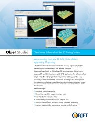
Figure 1 is a macro to make a simple test<br />
case, write facets, and run acon.exe. It also<br />
reads the ccon.mac file and parses out the<br />
area numbers to build components for each<br />
pair. Figure 2 shows output for that model<br />
<strong>in</strong> ccon.mac and figure 4 shows what would<br />
be <strong>in</strong> area.txt. Figure 3 shows the very<br />
excit<strong>in</strong>g model.<br />
If you use <strong>Workbench</strong>, this isn’t go<strong>in</strong>g to be<br />
much use to you, but if you are deal<strong>in</strong>g with<br />
large assemblies <strong>in</strong> <strong>ANSYS</strong>, with a little bit<br />
of script<strong>in</strong>g you might f<strong>in</strong>d it useful.<br />
Figure 1: Example Macro<br />
!Setup a blank model<br />
f<strong>in</strong>ish<br />
/clear<br />
/file,acontst<br />
/prep7<br />
!Build a flat plate with four cubes<br />
! on top with various gaps<br />
blc4,-1,-1,2,2,-.25<br />
blc4,-.5,-.5,.25,.25,.25<br />
blc4,.5,-.5,.25,.25,.25<br />
wpoff,,,0.05<br />
blc4,-.5,.5,.25,.25,.25<br />
wpoff,,,0.15<br />
blc4,.5,.5,.25,.25,.25<br />
!Turn on facet<strong>in</strong>g and force their<br />
! creation with an aplot<br />
/face,norml<br />
aplot<br />
!Write facets to file<br />
agwrite<br />
!Execute the acon.exe command<br />
/sys,acon acontst.afw 0 .005<br />
!Read and parse the contents of<br />
! ccon.mac to create components for<br />
! each pair<br />
*sread,lns,ccon.mac<br />
*get,nlns,PARM,lns,dim,2<br />
*do,ii,1,nlns-1<br />
aaa=strsub(lns(1,ii),14,20)<br />
c1=strpos(aaa,',')<br />
aa1 = valchr(strsub(aaa,1,c1-1))<br />
aaa = strsub(aaa,c1+1,20)<br />
c1=strpos(aaa,',')<br />
aa2 = valchr(strsub(aaa,1,c1-1))<br />
asel,s,area,,aa1<br />
cm,acn_%ii%a,area<br />
asel,s,area,,aa2<br />
cm,acn_%ii%b,area<br />
cmsel,a,acn_%ii%a<br />
cmgrp,acn_%ii%,acn_%ii%a,acn_%ii%b<br />
*enddo<br />
Figure 2: CCON.MAC Example<br />
asel,s,area,,2,7,5<br />
asel,a,area,,2,13,11<br />
aplot<br />
2,7<br />
2,13<br />
Figure 3: AREAS.TXT Example<br />
Figure 4: Example Geometry<br />
The Author’s sons<br />
battl<strong>in</strong>g Darth Vadar<br />
at Legoland... Hey it<br />
is a better space filler<br />
then another picture<br />
of Doug on top<br />
of a mounta<strong>in</strong>!<br />
www.padt<strong>in</strong>c.com 5 1-800-293-<strong>PADT</strong>
December 13, 2007 The Focus Issue 61<br />
Awesome APDL: Pars<strong>in</strong>g a Text File<br />
If you actually read the previous article on f<strong>in</strong>d<strong>in</strong>g areas that are<br />
close together <strong>in</strong> <strong>ANSYS</strong> us<strong>in</strong>g ACON.EXE, and you actually<br />
looked at the example macro, you will have noticed some fancy<br />
APDL at the end that parses a text file. So, us<strong>in</strong>g one stone to to<br />
kill two birds, we thought we would use the same macro for this<br />
issue’s Awesome APDL.<br />
Yes, I know, I should use python to parse the file. Python is the<br />
greatest tool <strong>in</strong>vented by man (or perhaps given to us by aliens) for<br />
deal<strong>in</strong>g with text files. But sometimes you want to keep everyth<strong>in</strong>g<br />
<strong>in</strong> one tool so it is portable. And APDL has most of what you need.<br />
In the example we have a file that conta<strong>in</strong>s ASEL commands that<br />
select area pairs we want to place <strong>in</strong> components. So we want to<br />
strip off the ASEL, get the two area numbers, and build some<br />
componetns.<br />
The first command that you need to learn well is *SREAD.<br />
Introduced about 3 or 4 years ago, *SREAD reads a text file and<br />
sticks each l<strong>in</strong>e <strong>in</strong> the file <strong>in</strong>to a text str<strong>in</strong>g. Basically, it makes an<br />
array of the text file:<br />
*SREAD,StrArray,Fname,Ext,,nChar,nSkip,nRead<br />
One of the nice th<strong>in</strong>gs about the command is that you don’t have to<br />
*DIM the array up front, it creates it for you. Check out the manual<br />
page for details on the command.<br />
So <strong>in</strong> our example, *SREAD reads the whole file and stores it <strong>in</strong><br />
the str<strong>in</strong>g array lns. Next, a *get is used to figure out how many<br />
l<strong>in</strong>es were read. That is used <strong>in</strong> a do loop, m<strong>in</strong>us the last l<strong>in</strong>e<br />
because it conta<strong>in</strong>s an aplot. For each l<strong>in</strong>e <strong>in</strong> the file, we want to<br />
chop off the first fourteen characters (asel,s,area,) then get the two<br />
numbers that follow it.<br />
So for the next bit we use the str<strong>in</strong>g functions <strong>in</strong> APDL, documented<br />
at the bottom of Appendix B <strong>in</strong> the <strong>ANSYS</strong> Parametric Design<br />
Language Manual (do a search on strpos <strong>in</strong> help to f<strong>in</strong>d it). We use<br />
STRSUB to grab characters 14 through 20. Then STRPOS to<br />
count characters to the comma that separates the numbers (c1).<br />
VALCHR is used with an embedded STRSUB to convert the str<strong>in</strong>g<br />
<strong>in</strong>to a number. Then we use STRSUB aga<strong>in</strong> to grab the second<br />
number on, f<strong>in</strong>d the next comma with STRPOS and use VALCHR<br />
aga<strong>in</strong> to get the second number.<br />
The rest of the macro is a fairly standard use of parameter substitution<br />
to select values and create components.<br />
Example Input:<br />
asel,s,area,,2,7,5<br />
asel,a,area,,2,13,11<br />
Aplot<br />
Example Code:<br />
*sread,lns,ccon.mac<br />
*get,nlns,PARM,lns,dim,2<br />
*do,ii,1,nlns-1<br />
aaa=strsub(lns(1,ii),14,20)<br />
c1=strpos(aaa,',')<br />
aa1 = valchr(strsub(aaa,1,c1-1))<br />
aaa = strsub(aaa,c1+1,20)<br />
c1=strpos(aaa,',')<br />
aa2 = valchr(strsub(aaa,1,c1-1))<br />
asel,s,area,,aa1<br />
cm,acn_%ii%a,area<br />
asel,s,area,,aa2<br />
cm,acn_%ii%b,area<br />
cmsel,a,acn_%ii%a<br />
cmgrp,acn_%ii%,acn_%ii%a,acn_%ii%b<br />
*enddo<br />
News - L<strong>in</strong>ks - Info<br />
· <strong>ANSYS</strong> and LSTC renew agreement and keep LS-<br />
DYNA <strong>in</strong> <strong>ANSYS</strong> alive. <br />
· Zuken and <strong>ANSYS</strong> agree to work together on better<br />
E<strong>CAD</strong> <strong>in</strong>tegration. <br />
· <strong>ANSYS</strong> and Network Analysis team up and release<br />
<strong>Workbench</strong> connection for SINDA/G <br />
· The latest <strong>ANSYS</strong> Advantage magaz<strong>in</strong>e is out and<br />
is a real nice publication. Much more technical than<br />
<strong>in</strong> the past. Read and/or subscribe here: <br />
· Need material test<strong>in</strong>g, try: Datapo<strong>in</strong>t Labs, Matereality<br />
or Axel Products<br />
Upcom<strong>in</strong>g Tra<strong>in</strong><strong>in</strong>g Classes<br />
Month Start End # Title Location<br />
Jan ‘08 1/14 1/16 101 Introduction to <strong>ANSYS</strong>, Part I Tempe, AZ<br />
1/17 1/18 100 Eng<strong>in</strong>eer<strong>in</strong>g with FEA Tempe, AZ<br />
1/24 1/25 801 <strong>ANSYS</strong> Customization with APDL Tempe, AZ<br />
1/28 1/29 104 <strong>ANSYS</strong> WB Simulation – Intro ALBQ, NM<br />
1/30 1/31 207 WB – Structural Nonl<strong>in</strong>earities ALBQ, NM<br />
1/31 2/1 301 Heat Transfer Tempe, AZ<br />
Feb '08 2/4 2/5 107 <strong>ANSYS</strong> WB DesignModeler Tempe, AZ<br />
2/6 2/6 411 WB Simulation Electromagnetics Tempe, AZ<br />
2/7 2/8 205 WB Simulation Dynamics Tempe, AZ<br />
2/21 2/21 206 WB Rigid & Flexible Dynamics Tempe, AZ<br />
2/25 2/26 202 Advanced Structural NL Tempe, AZ<br />
Mar '08 3/3 3/4 104 <strong>ANSYS</strong> WB Simulation – Intro Tempe, AZ<br />
3/5 3/6 207 WB – Structural Nonl<strong>in</strong>earities Tempe, AZ<br />
3/10 3/11 203 Dynamics Tempe, AZ<br />
3/17 3/18 501 <strong>ANSYS</strong>/LS-DYNA Tempe, AZ<br />
3/26 3/28 902 Multiphysics Simulation for MEMS Tempe, AZ<br />
The Focus is a periodic publication of Phoenix Analysis & Design Technologies (<strong>PADT</strong>). Its goal is to educate and enterta<strong>in</strong> the worldwide AN-<br />
SYS user community. More <strong>in</strong>formation on this publication can be found at: http://www.padt<strong>in</strong>c.com/epubs/focus/about<br />
www.padt<strong>in</strong>c.com 6 1-800-293-<strong>PADT</strong>
December 13, 2007 The Focus Issue 61<br />
www.padt<strong>in</strong>c.com 7 1-800-293-<strong>PADT</strong>