Using CAD Parameters within ANSYS Using NLDIAG ... - PADT
Using CAD Parameters within ANSYS Using NLDIAG ... - PADT
Using CAD Parameters within ANSYS Using NLDIAG ... - PADT

You also want an ePaper? Increase the reach of your titles
YUMPU automatically turns print PDFs into web optimized ePapers that Google loves.
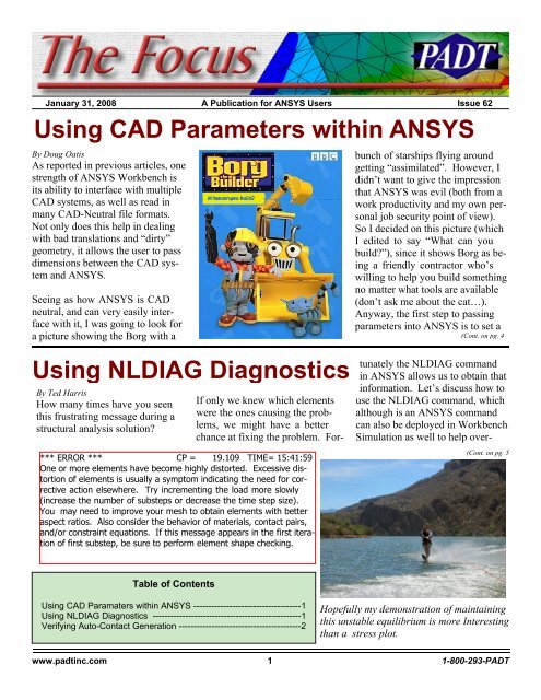
January 31, 2008 The Focus Issue 62<br />
January 31, 2008 A Publication for <strong>ANSYS</strong> Users Issue 62<br />
<strong>Using</strong> <strong>CAD</strong> <strong>Parameters</strong> <strong>within</strong> <strong>ANSYS</strong><br />
By Doug Oatis<br />
As reported in previous articles, one<br />
strength of <strong>ANSYS</strong> Workbench is<br />
its ability to interface with multiple<br />
<strong>CAD</strong> systems, as well as read in<br />
many <strong>CAD</strong>-Neutral file formats.<br />
Not only does this help in dealing<br />
with bad translations and “dirty”<br />
geometry, it allows the user to pass<br />
dimensions between the <strong>CAD</strong> system<br />
and <strong>ANSYS</strong>.<br />
Seeing as how <strong>ANSYS</strong> is <strong>CAD</strong><br />
neutral, and can very easily interface<br />
with it, I was going to look for<br />
a picture showing the Borg with a<br />
<strong>Using</strong> <strong>NLDIAG</strong> Diagnostics<br />
By Ted Harris<br />
How many times have you seen<br />
this frustrating message during a<br />
structural analysis solution?<br />
*** ERROR *** CP = 19.109 TIME= 15:41:59<br />
One or more elements have become highly distorted. Excessive distortion<br />
of elements is usually a symptom indicating the need for corrective<br />
action elsewhere. Try incrementing the load more slowly<br />
(increase the number of substeps or decrease the time step size).<br />
You may need to improve your mesh to obtain elements with better<br />
aspect ratios. Also consider the behavior of materials, contact pairs,<br />
and/or constraint equations. If this message appears in the first iteration<br />
of first substep, be sure to perform element shape checking.<br />
bunch of starships flying around<br />
getting “assimilated”. However, I<br />
didn’t want to give the impression<br />
that <strong>ANSYS</strong> was evil (both from a<br />
work productivity and my own personal<br />
job security point of view).<br />
So I decided on this picture (which<br />
I edited to say “What can you<br />
build?”), since it shows Borg as being<br />
a friendly contractor who’s<br />
willing to help you build something<br />
no matter what tools are available<br />
(don’t ask me about the cat…).<br />
Anyway, the first step to passing<br />
parameters into <strong>ANSYS</strong> is to set a<br />
(Cont. on pg. 4<br />
If only we knew which elements<br />
were the ones causing the problems,<br />
we might have a better<br />
chance at fixing the problem. Fortunately<br />
the <strong>NLDIAG</strong> command<br />
in <strong>ANSYS</strong> allows us to obtain that<br />
information. Let’s discuss how to<br />
use the <strong>NLDIAG</strong> command, which<br />
although is an <strong>ANSYS</strong> command<br />
can also be deployed in Workbench<br />
Simulation as well to help over-<br />
(Cont. on pg. 5<br />
Table of Contents<br />
<strong>Using</strong> <strong>CAD</strong> Paramaters <strong>within</strong> <strong>ANSYS</strong> ------------------------------------1<br />
<strong>Using</strong> <strong>NLDIAG</strong> Diagnostics --------------------------------------------------1<br />
Verifying Auto-Contact Generation -----------------------------------------2<br />
Hopefully my demonstration of maintaining<br />
this unstable equilibrium is more Interesting<br />
than a stress plot.<br />
www.padtinc.com 1 1-800-293-<strong>PADT</strong>
January 31, 2008 The Focus Issue 62<br />
Verifying Auto-Contact Generation<br />
By Rod Scholl<br />
How does it go? “With<br />
great power comes great<br />
responsibility”? This is<br />
the case with Workbench<br />
Simulation’s automatic<br />
interface detection. After<br />
contact regions are detected,<br />
it is necessary to verify<br />
each connection to avoid<br />
what I will call “wraparound<br />
areas” from being<br />
erroneously included in<br />
the contact region.<br />
Case A:<br />
This is a block dropped<br />
into a rectangular cutout<br />
as shown in Figures 1, 2,<br />
and 3. We only want contact<br />
at the bottom face as<br />
shown in Figure 3, and<br />
thus note that there is a<br />
single face in the contact<br />
pair as shown in Figure 4.<br />
For a test case we’ll slap<br />
on some BC’s as shown in<br />
Figure 5, and look at<br />
equivalent stress as shown<br />
in Figure 6 and 7.<br />
(Cont. on pg. 3<br />
Case A<br />
Figure 1<br />
Figure 3<br />
In x-section<br />
Figure 2<br />
Figure 4<br />
Figure 5<br />
Figure 6<br />
Figure 7<br />
www.padtinc.com 2 1-800-293-<strong>PADT</strong>
January 31, 2008 The Focus Issue 62<br />
Case B: (Auto-Contact, cont...)<br />
In this case, we let auto-contact<br />
find the interface. Here<br />
it grabs the surfaces on the<br />
side of the rectangular indent<br />
as shown in Figure 8 and we<br />
see there are 3 pairs of surfaces<br />
in Figure 9. Now we<br />
look at stresses under the<br />
same BC’s and note in Figure<br />
10 and 11 that they are<br />
24% lower!:<br />
So clearly a large “wrap-around” contact<br />
surface can greatly alter your results,<br />
and one needs to check every<br />
interface and examine each of its involved<br />
faces.<br />
This rectangular cutout in case A and B<br />
was pretty large, and thus the sizeable<br />
impact on results. I repeated the comparison<br />
in using a much more shallow<br />
contact region as shown in Figure 12 of<br />
the type which would be easy to overlook<br />
on an imported geometry. Here we<br />
see in Figures 13 and 14 that the stress<br />
on the front face decreases 11.8%,<br />
which is still appreciable.<br />
Figure 8 Figure 9<br />
Figure 10<br />
Figure 11<br />
I should probably finish up with some finger wagging, pacing, and warnings about planes falling out of the<br />
sky… but instead I’ll just say, “check your auto-created contact surfaces one by one not just visually but my<br />
number of surfaces in each region; it can impact the results dramatically…”.<br />
Figure 12 Figure 13 Figure 14<br />
www.padtinc.com 3 1-800-293-<strong>PADT</strong>
January 31, 2008 The Focus Issue 62<br />
assemblies of parts that have<br />
hundreds of features (all of<br />
which have some dimension<br />
driving them).<br />
(<strong>CAD</strong> <strong>Parameters</strong>, cont...)<br />
prefix name. By default <strong>ANSYS</strong><br />
looks for any dimension who’s<br />
name begins with ‘DS’. You can<br />
see this preset in multiple places;<br />
the Project Page “Default Geometry<br />
Option”, Design Modeler “Details<br />
of Attach”, and Simulation “Details<br />
So now we need to go into our<br />
<strong>CAD</strong> system (Pro/E is shown<br />
right) and modify the name of<br />
a dimension to include the DS<br />
prefix. As shown, while editing<br />
a feature, I right clicked on<br />
a dimension and brought up<br />
the ‘Properties’ window. One<br />
of the tabs is “Dimension<br />
Text”, which contains the default<br />
name. Simply add the ‘DS’<br />
prefix in there and you’re ready to<br />
go.<br />
Next, launch <strong>ANSYS</strong> as you normally<br />
would through the provided<br />
drop-down ‘<strong>ANSYS</strong>’ menu. When<br />
you’ve finished importing the geometry<br />
you should see your dimension<br />
listed in the details widow.<br />
For Design Modeler, the dimension<br />
will appear in the details on the<br />
‘Attach’ object in the tree. For<br />
Simulation, the dimension will<br />
appear in the details window<br />
for the part the dimension is<br />
attached to (see pictures to the<br />
right).<br />
of Geometry”. If you set the key to<br />
be blank, then it will import EV-<br />
ERY dimension in your model.<br />
This might be okay for a small<br />
model, but if you’re a hot-shot analyst<br />
like me, you’re working with<br />
Now after you’ve been doing<br />
this a while, you may notice<br />
that if you bring the dimension<br />
into DM, it isn’t carried over<br />
into Simulation. That’s because<br />
the dimension is only a<br />
local parameter, and isn’t carried<br />
over into subsequent modules.<br />
You can promote this dimension<br />
by “parameterizing” it (click the<br />
empty box next to the dimension<br />
name), thereby promoting it to a<br />
global value. You will then be able<br />
to see it in the parameter manager<br />
in Simulation.<br />
www.padtinc.com 4 1-800-293-<strong>PADT</strong>
January 31, 2008 The Focus Issue 62<br />
(<strong>CAD</strong> <strong>Parameters</strong>, cont...)<br />
Workbench Module, DesignXplorer.<br />
supported <strong>CAD</strong> package<br />
At this point you’re really ready to<br />
DX (as it’s known on the street) (SolidWorks, Pro/E, SolidEdge,<br />
rock and roll. If you want to allows for easy setup of parametric Catia V5, etc.).<br />
change the dimension, simply enter design studies, as long as you have For the rest of you wondering what<br />
in the new value in the details window.<br />
at least one input and one output I’ve been talking about, just watch<br />
Next refresh the geometry parameter.<br />
MTV’s Pimp My Ride (check your<br />
with either the DesignModeler or If you don’t have a DX license, you local cable provider for availability<br />
Simulation Parameter values can only do manual DOE runs, and listings).<br />
(depending on which module where you are responsible for creating<br />
you’re in). When <strong>ANSYS</strong> refreshes,<br />
all the design points. If you Word.<br />
it will go back to the <strong>CAD</strong> system,<br />
have a DX license, then get ready to<br />
pass the new dimension, wait pimp your analysis. DX offers<br />
for the <strong>CAD</strong> to regenerate the model,<br />
many parametric study types and<br />
re-import, and then perform all sampling routines, which allow you<br />
preprocessor operations you did on to specify distributions of inputs<br />
it in DM or Simualtion. If the regeneration<br />
and automatically create the re-<br />
causes large topology quired number of design points.<br />
changes, then you may need to redo This allows you to really look into<br />
some setup work (but this isn’t a how sensitive your part is to various<br />
very common occurance). If you geometric tolerances.<br />
want to pull in the dimensions from So for all you analysts out there<br />
your <strong>CAD</strong> model, then tell it to use keepin it street (alright, I’m done<br />
the ‘Geometry’ parameter values. with hip hop references), remember<br />
This way you can drive the analysis you can truly simplify your life and<br />
from both sides, <strong>CAD</strong> and <strong>ANSYS</strong>. shorten your analysis cycle by using<br />
Once you get comfortable with this, <strong>CAD</strong> parameters. All that’s required<br />
you can use rapper Xzibit’s favorite<br />
is the proper license, and a<br />
(<strong>NLDIAG</strong>, cont...)<br />
come convergence difficulties in<br />
nonlinear structural analyses.<br />
Both <strong>ANSYS</strong> and Workbench Simulation<br />
allow us to plot the Newton-<br />
Raphson residuals. These plots are<br />
color contours of the imbalance in<br />
the system for a given equilibrium<br />
iteration. The locations of highest<br />
residuals show where the imbalance<br />
is greatest in the model. The use of<br />
the <strong>NLDIAG</strong> command to create<br />
these plots in <strong>ANSYS</strong> was discussed<br />
in a previous Focus article.<br />
You may find this other article useful<br />
in understanding the Newton-<br />
Raphson nonlinear solution method.<br />
The rest of this article will discuss<br />
the additional capability of NL-<br />
DIAG besides plotting Newton-<br />
Raphson residuals. Before we<br />
move on, however, note that those<br />
residuals can be plotted in Workbench<br />
Simulation 11.0 by highlighting<br />
the Solution Information branch<br />
and changing the Details of Newton-Raphson<br />
Residuals to a number<br />
greater than 0.<br />
The <strong>NLDIAG</strong> command can be<br />
used to produce additional nonlinear<br />
diagnostic information such as<br />
which elements have triggered a<br />
bisection or nonconvergence due to<br />
1. Excessive distortion<br />
2. Exceeding the allowable<br />
plastic strain for a substep<br />
3. Exceeding the allowable<br />
creep strain for a substep<br />
4. Having nodes with nearzero<br />
pivots<br />
5. Having violated the Mixed<br />
U-P constraints (18X elements)<br />
In addition to telling us the elements<br />
which have encountered the<br />
above problems, the load step, substep,<br />
and cumulative iteration at<br />
which the problems occurred are<br />
stored as well.<br />
<strong>NLDIAG</strong> can also be used to store<br />
contact diagnostic information for<br />
each contact element during solu-<br />
www.padtinc.com 5 1-800-293-<strong>PADT</strong>
January 31, 2008 The Focus Issue 62<br />
from the default of 4, shown to the files will look like the example<br />
right.<br />
shown below.<br />
If we want to use <strong>NLDIAG</strong> to<br />
track element convergence problems<br />
<strong>within</strong> <strong>ANSYS</strong> Workbench<br />
Simulation, we need to insert a<br />
command snippet under the Solution<br />
branch using those commands.<br />
(<strong>NLDIAG</strong>, cont...)<br />
tion. The type of information<br />
stored can be the number of elements<br />
in contact, the maximum<br />
penetration, the maximum contact<br />
stress, etc. More details on the information<br />
available for contact elements<br />
is available in the <strong>ANSYS</strong><br />
Help for the <strong>NLDIAG</strong> command.<br />
<strong>NLDIAG</strong> produces no data unless<br />
we turn it on either through issuing<br />
the command with the appropriate<br />
options or by activating it in the<br />
<strong>ANSYS</strong> environment menu. The<br />
trick is that you have to activate it<br />
before you have difficulty, so it’s<br />
not a bad idea to activate it on your<br />
first attempt at solving.<br />
The command format to have it<br />
track element events as described<br />
above is shown below:<br />
<strong>NLDIAG</strong>,EFLG,1<br />
!write diagnostic files<br />
Also, by default only information<br />
for the most recent four equilibrium<br />
iterations is stored. If we<br />
want to be able to keep track of<br />
events which may have occurred<br />
earlier in the solution we need to<br />
increase the number of files<br />
stored with the MAXF option of<br />
<strong>NLDIAG</strong>, such as the following:<br />
<strong>NLDIAG</strong>, MAXF, 200<br />
!Store 200 files max<br />
This can also be accomplished<br />
from the<br />
<strong>ANSYS</strong> user interface,<br />
by clicking on<br />
Solution > Diagnostics<br />
> Nonlinear Diagnostics.<br />
The<br />
number of previous<br />
iterations to save can<br />
then be increased<br />
<strong>NLDIAG</strong>,MAXF,200<br />
<strong>NLDIAG</strong>,EFLG,1<br />
For example,<br />
As the solution progresses, nonlinear<br />
diagnostic information will be<br />
written to files with the naming<br />
convention .nd001,<br />
.nd002, etc. The content of the<br />
/COM,<strong>ANSYS</strong> RELEASE 11.0SP1<br />
test110sp1.nd012<br />
1 2 1 13 0 420<br />
1 0 0 0 0 0<br />
2 0 0 0 0 0<br />
3 0 0 0 0 0<br />
4 0 0 0 0 0<br />
5 0 0 0 0 0<br />
6 0 0 0 0 0<br />
7 0 0 0 0 0<br />
.......snip.......<br />
372 0 0 0 0 0<br />
373 0 0 0 0 0<br />
374 0 1 0 0 0<br />
375 0 0 0 0 0<br />
376 0 0 0 0 0<br />
377 0 0 0 0 0<br />
The first line that starts with “1”<br />
indicates that this file is for substep<br />
2, load step 1, cumulative iteration<br />
13, and that there are 420 elements<br />
in the model. The 1 in field 3 in<br />
the line that starts with 374 indicates<br />
that element 374 had excessive<br />
element distortion for this<br />
equilibrium iteration.<br />
Fortunately, there is an easier and<br />
better way to review the content of<br />
these files than to hunt for “1”s in<br />
a sea of zeroes in a text editor.<br />
The <strong>ANSYS</strong> /POST1 General<br />
Postprocessor has a nice tool for<br />
coalescing the information in the<br />
nonlinear diagnostic files into<br />
something we can quickly and easily<br />
use. To do that, we activate the<br />
<strong>ANSYS</strong> interface in the working<br />
directory in which our diagnostic<br />
files reside, making sure our jobname<br />
matches our diagnostic file<br />
name prefixes (this will be “file” if<br />
using Workbench Simulation).<br />
<strong>PADT</strong> is pleased to announce the<br />
latest additions to our rapid manufacturing<br />
tools set: a CNC Mill and<br />
Lathe. They will compliment our<br />
existing manual lathe and mill<br />
along with our array of Rapid Prototyping<br />
machines and injection<br />
molding equipment.<br />
If you would like to see these new<br />
machines, or learn more about any<br />
part of <strong>PADT</strong>, please call (480 813-<br />
4884) or drop us an e-<br />
mail(info@padtinc.com)<br />
www.padtinc.com 6 1-800-293-<strong>PADT</strong>
January 31, 2008 The Focus Issue 62<br />
(<strong>NLDIAG</strong>, cont...)<br />
Next we click on General Postprocessor<br />
> Read Results > Last<br />
Set and then click on Nonlinear<br />
Diagnostics.<br />
In the image to the right the<br />
highlighted row shows that at<br />
time 0.3, load step 1, substep 2,<br />
cumulative iteration 13 there<br />
was an element that exceeded<br />
the allowable amount of distortion.<br />
News - Links - Info<br />
· One set of FLUENT tools that <strong>PADT</strong> is getting<br />
very excited about and seeing a lot of<br />
interest in for resources electronics people,<br />
are the ICEPak packages. Visit<br />
www.icepak.com to learn more.<br />
· Did you know <strong>PADT</strong> has extensive capabilities<br />
in Rapid Prototyping? Learn more!<br />
· Visit <strong>PADT</strong>”s SWAU Resource Center.<br />
These tools, and publications are designed<br />
for our customers in the southwest, but will<br />
be useful to all <strong>ANSYS</strong> users.<br />
· View the collection of undocumented AN-<br />
SYS commands.<br />
· Design your new computer (or justify the a<br />
purchase) using <strong>PADT</strong>’s benchmark site.<br />
At the bottom of the above<br />
menu screen we can type in a<br />
name for an <strong>ANSYS</strong> element<br />
component and then click on the<br />
Generate Components button. That<br />
will create a named group of elements<br />
that we can then select and<br />
plot or otherwise investigate. Plotting<br />
the element which has undergone<br />
too much distortion may show<br />
us that it was poorly shaped to begin<br />
with or that it was improperly<br />
constrained, etc. Hopefully this is<br />
information that will help us to take<br />
corrective action to allow our solution<br />
to converge for the full load.<br />
The element component names will<br />
use the prefix we specify followed<br />
by a special naming convention<br />
depending on what type of problem<br />
the elements encountered. This<br />
naming convention is described in<br />
the documentation for the <strong>NLDIAG</strong><br />
command in the <strong>ANSYS</strong> help.<br />
So the <strong>NLDIAG</strong> command gives us<br />
one more tool in our belt to help us<br />
overcome structural convergence<br />
difficulties. The capability is available<br />
in Workbench Simulation by<br />
inserting the appropriate <strong>NLDIAG</strong><br />
commands under the Solution<br />
branch, but the post-processing of<br />
the <strong>NLDIAG</strong>,EFLG data for element<br />
convergence troubles is best<br />
performed in the <strong>ANSYS</strong> General<br />
Postprocessor, as of version 11.0.<br />
Upcoming Training Classes<br />
Month Start End # Title Location<br />
Feb '08 2/4 2/5 107 <strong>ANSYS</strong> WB DesignModeler Tempe, AZ<br />
2/6 2/6 411 WB Simulation Electromagnetics Tempe, AZ<br />
2/7 2/8 205 WB Simulation Dynamics Tempe, AZ<br />
2/21 2/21 206 WB Rigid & Flexible Dynamics Tempe, AZ<br />
2/25 2/26 202 Advanced Structural NL Tempe, AZ<br />
Mar '08 3/3 3/4 104 <strong>ANSYS</strong> WB Simulation – Intro Tempe, AZ<br />
3/5 3/6 207 WB – Structural Nonlinearities Tempe, AZ<br />
3/10 3/11 203 Dynamics Tempe, AZ<br />
3/17 3/18 501 <strong>ANSYS</strong>/LS-DYNA Tempe, AZ<br />
3/26 3/28 902 Multiphysics Simulation for MEMS Tempe, AZ<br />
Apr ‘08 4/2 4/4 101 Introduction to <strong>ANSYS</strong>, Part I Tempe, AZ<br />
4/7 4/8 107 <strong>ANSYS</strong> WB DesignModeler Tempe, AZ<br />
4/9 4/11 401 Low Frequency Electromagnetics Tempe, AZ<br />
4/14 4/15 604 Introduction to CFX Tempe, AZ<br />
4/21 4/22 201 Basic Structural Nonlinearities Tempe, AZ<br />
4/23 4/24 204 Advanced Contact and Fasteners Tempe, AZ<br />
www.padtinc.com 7 1-800-293-<strong>PADT</strong>
January 31, 2008 The Focus Issue 62<br />
GOT CFD?<br />
Whether you feel you need to start implementing CFD into your engineering analysis or<br />
you are looking for increased compute power, <strong>PADT</strong>, Inc. can assist you! We use two of<br />
the best and most comprehensive CFD tools available, FLUENT and CFX, which are unmatched<br />
in their breadth and depth of capability when solving the toughest or even the<br />
simplest CFD problems.<br />
<strong>PADT</strong>, Inc. has CFD engineers with over 15 years of experience using FLUENT, CFX and a<br />
host of other CFD codes. This experience enables us to quickly assess an application,<br />
understand the challenges and provide you with timely, accurate and detailed results.<br />
Give us a call or send us an email if you:<br />
· Want to bring CFD into your engineering design and<br />
analysis and don’t currently have the expertise?<br />
· Don’t have the compute power to solve larger CFD<br />
problems?<br />
· Have purchased CFX or FLUENT and want some help,<br />
such as mentoring or services to get up to speed<br />
more quickly?<br />
· Need a CFD job done now!?<br />
· Or just need additional CFD resources...<br />
To speak with someone about your CFD and other engineering<br />
needs, please contact Stephen Hendry, visit us online, or call 1-800-<br />
293-<strong>PADT</strong> (7238).<br />
www.padtinc.com 8 1-800-293-<strong>PADT</strong>