

AxSOS Distal Tibia Alternating treaded shaft holes Operative - Stryker
AxSOS Distal Tibia Alternating treaded shaft holes Operative - Stryker
AxSOS Distal Tibia Alternating treaded shaft holes Operative - Stryker

You also want an ePaper? Increase the reach of your titles
YUMPU automatically turns print PDFs into web optimized ePapers that Google loves.
<strong>Operative</strong> Technique<br />
Option 2 – Locking Screws<br />
4.0mm Locking Screws can be placed<br />
in the threaded <strong>shaft</strong> <strong>holes</strong> or <strong>holes</strong><br />
with pre-placed Locking Inserts.<br />
Use the Drill Sleeve (REF 702707) to<br />
pre-drill the core hole for subsequent<br />
Locking Screw placement. The Drill<br />
Sleeve should be fully inserted into the<br />
pre-threaded hole or Locking Insert to<br />
ensure initial fixation of the Locking<br />
Insert into the plate.<br />
T15 (REF 702753) and the Screw Holding<br />
Sleeve (REF 702732) together with<br />
the Torque Limiting Attachment<br />
(REF 702750) and the T-Handle<br />
(REF 702427).<br />
Note:<br />
Ensure that the screwdriver tip is<br />
fully seated in the screw head, but<br />
do not apply axial force during<br />
final tightening.<br />
A 3.1mm Drill Bit (REF 702742) is<br />
used to drill through both cortices<br />
(Fig. 15).<br />
Note:<br />
Avoid any angulation or excessive<br />
force on the drill, as this could<br />
dislodge the Locking Insert.<br />
The screw measurement is then taken.<br />
The appropriate sized Locking Screw<br />
is then inserted using the Screwdriver<br />
Maximum stability of the Locking<br />
Insert is achieved once the screw is<br />
fully seated and tightened to 4.0Nm.<br />
This procedure is repeated for all <strong>holes</strong><br />
chosen for locked <strong>shaft</strong> fixation.<br />
All provisional plate fixation devices<br />
(K-Wires, Temporary Plate Holder, etc)<br />
can now be removed.<br />
Fig. 15<br />
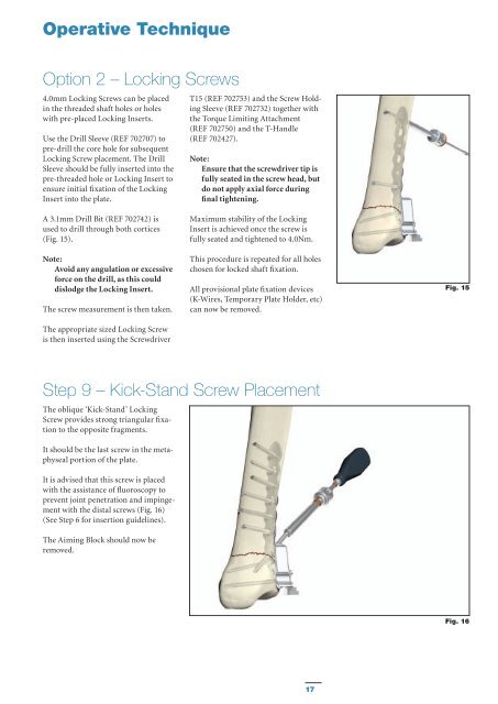
Step 9 – Kick-Stand Screw Placement<br />
The oblique ‘Kick-Stand’ Locking<br />
Screw provides strong triangular fixation<br />
to the opposite fragments.<br />
It should be the last screw in the metaphyseal<br />
portion of the plate.<br />
It is advised that this screw is placed<br />
with the assistance of fluoroscopy to<br />
prevent joint penetration and impingement<br />
with the distal screws (Fig. 16)<br />
(See Step 6 for insertion guidelines).<br />
The Aiming Block should now be<br />
removed.<br />
Fig. 16<br />
17


