AxSOS Distal Tibia Alternating treaded shaft holes Operative - Stryker
AxSOS Distal Tibia Alternating treaded shaft holes Operative - Stryker AxSOS Distal Tibia Alternating treaded shaft holes Operative - Stryker
Operative Technique Step 2a – Locking Insert Extraction Should removal of a Locking Insert be required for any reason, then the following procedure should be used. Thread the central portion (A) of the Locking Insert Extractor (REF 702767) into the Locking Insert that you wish to remove until it is fully seated (Fig. 2B). B A Then turn the outer sleeve/collet (B) clockwise until it pulls the Locking Insert out of the plate (Fig. 2C). The Locking Insert should then be discarded, as it should not be reused. Fig. 2B Fig. 2C Step 2b – Intra-Operative Locking Insert Application If desired, a Locking Insert can be applied in a standrad hole in the shaft of the plate intra-operatively by using the Locking Insert Forceps (REF 702968), Centering Pin (REF 702673), Adaptor for Centering Pin (REF 702675), and Guide for Centering Pin (REF 702671). First, the Centering Pin is inserted through the chosen hole using the adaptor and guide (Fig. 3A). It is important to use the guide as this centers the core hole for Locking Screw insertion after the Locking Insert is applied. After inserting the Centering Pin bi-cortically, remove the adaptor and guide. Fig. 3A Next, place a Locking Insert on the end of the forceps and slide the instrument over the centering pin down to the hole. Last, apply the Locking Insert by triggering the forceps handle. Push the button on the forceps to remove the device . At this time, remove the centering pin (Fig. 3B). Fig. 3B 10
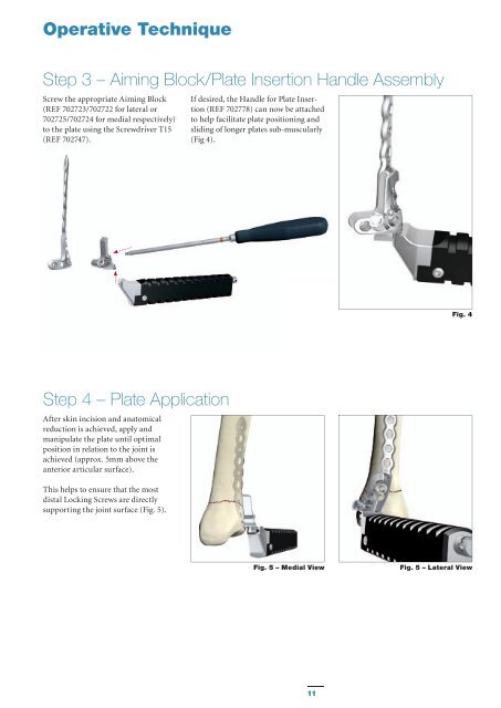
Operative Technique Step 3 – Aiming Block/Plate Insertion Handle Assembly Screw the appropriate Aiming Block (REF 702723/702722 for lateral or 702725/702724 for medial respectively) to the plate using the Screwdriver T15 (REF 702747). If desired, the Handle for Plate Insertion (REF 702778) can now be attached to help facilitate plate positioning and sliding of longer plates sub-muscularly (Fig 4). Fig. 4 Step 4 – Plate Application After skin incision and anatomical reduction is achieved, apply and manipulate the plate until optimal position in relation to the joint is achieved (approx. 5mm above the anterior articular surface). This helps to ensure that the most distal Locking Screws are directly supporting the joint surface (Fig. 5). Fig. 5 – Medial View Fig. 5 – Lateral View 11
- Page 1 and 2: Tibia & Fibula AxSOS KnifeLight Loc
- Page 3 and 4: Contents Page 1. Introduction 4 2.
- Page 5 and 6: Features & Benefits System The ante
- Page 7 and 8: Operative Technique General Guideli
- Page 9: Operative Technique Step 1 - Pre-Op
- Page 13 and 14: Operative Technique Step 6 - Primar
- Page 15 and 16: Operative Technique Final tightenin
- Page 17 and 18: Operative Technique Option 2 - Lock
- Page 19 and 20: Operative Technique With the aid of
- Page 21 and 22: Additional Tips 1. Always use the t
- Page 23 and 24: Ordering Information - Implants 4.0
- Page 25 and 26: Ordering Information - Instruments
- Page 27 and 28: Additional Information - HydroSet I
<strong>Operative</strong> Technique<br />
Step 3 – Aiming Block/Plate Insertion Handle Assembly<br />
Screw the appropriate Aiming Block<br />
(REF 702723/702722 for lateral or<br />
702725/702724 for medial respectively)<br />
to the plate using the Screwdriver T15<br />
(REF 702747).<br />
If desired, the Handle for Plate Insertion<br />
(REF 702778) can now be attached<br />
to help facilitate plate positioning and<br />
sliding of longer plates sub-muscularly<br />
(Fig 4).<br />
Fig. 4<br />
Step 4 – Plate Application<br />
After skin incision and anatomical<br />
reduction is achieved, apply and<br />
manipulate the plate until optimal<br />
position in relation to the joint is<br />
achieved (approx. 5mm above the<br />
anterior articular surface).<br />
This helps to ensure that the most<br />
distal Locking Screws are directly<br />
supporting the joint surface (Fig. 5).<br />
Fig. 5 – Medial View<br />
Fig. 5 – Lateral View<br />
11


