T2 Ankle Arthrodesis Nail - Stryker
T2 Ankle Arthrodesis Nail - Stryker T2 Ankle Arthrodesis Nail - Stryker
Operative Technique Target Device Assembly • Pre-load the Compression Screw (1818-0001S). Use the Compression Screwdriver (1806-3210) to insert the Compression Screw into the nail (Fig. 11a). Make sure the screw is set between the round and the oblong hole. Fig 11a Prior to nail insertion, the Ball Tip Guide Wire must be exchanged for a Smooth Tip Guide Wire. The pre-loaded Compression Screw is cannulated but does not allow the ball tip to pass through. • Assemble the Apposition Handle (1806-3215) onto the Nail Adapter (1806-3211). Turn the Apposition Handle until the end of the threads in order not to influence the insertion depth of the nail (Fig. 11b). • Attach the selected nail to the Nail Adapter (Fig. 11c) until it´s 3 connection teeth engage into the corresponding slots of the Nail. The Nail Holding Screw (1806- 3203) is placed through the Nail Adapter and tightened securely with the Insertion Wrench (1806- 0135) and Wrench 8/10mm (1806- 0130) to avoid loosening during Nail insertion. Engravings on the Nail Adapter will indicate lateral direction. Fig 11b Fig 11c • Insert the Target Arm (1806-3212) over the Nail Adapter and lock it in the “Lateral Locking” position. Attach the Aiming Adapter (1806- 3216) and secure the whole assembly by tightening the Nut (1806-3213) (Fig. 12). Prior to nail insertion please check correct alignment of the Targeting Device by inserting a Ø4.2 × 340mm Drill (1806-4260S) through the assembled Tissue Protection (1806- 0185) and Drill Sleeve, Long, (1806- 0215) placed into the Targeting Arm and targeting all “Lateral Locking” holes of the implant. Note: If the Apposition Sleeve (1806- 3214) is to be used, slide it over the nail and Nail Adapter prior to nail insertion. Note: The Aiming Adapter should be attached only when the Target Arm is mounted on the Nail Adapter in the “Lateral Locking” position. Check alignment of the P/A calcaneal hole by passing a K-Wire through the Aiming Adapter. Apposition Sleeve Nut Fig 12 12
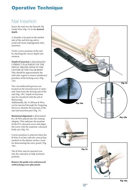
Operative Technique Nail Insertion Insert the nail over the Smooth Tip Guide Wire (Fig. 13) to the desired depth. A chamfer is located on the medial side of the nail driving end to avoid soft tissue impingement after insertion. Verify correct position of the nail by checking the correct depth and rotation. Depth of insertion is determined by CORRECT PLACEMENT OF THE DISTAL OBLONG HOLE IN THE CENTER OF THE TALAR BODY. This should be approximately the mid-talar region to ensure satisfactory purchase of the locking screw (Fig. 13a). Two circumferential grooves are located on the insertion post at 2mm and 7mm from the driving end of the nail (Fig. 13b). Depth of insertion may be visualized with the aid of fluoroscopy. Additionally, the 3×285mm K-Wire can be inserted through the Targeting Device to identify the junction of the nail and insertion post (Fig. 13). Fig 13a 2mm 7mm Fig 13 Rotational alignment is determined by a K-Wire placed into the Aiming Adapter. This indicates the position of the P/A calcaneal screw and aligns the screw with the anatomic calcaneal body axis (Fig. 14). Fig 13b Correct position is achieved when the K-Wire is in line with the vertical line marked on the plantar surface (used for determining the entry point) (Fig. 14a). The K-Wire may be inserted 1cm into the calcaneus to help maintain position. Fig 14 Remove the guide wire and proceed with locking screw placement. Fig 14a 13
- Page 1 and 2: T2 Ankle Arthrodesis Nail Operative
- Page 3 and 4: Contents Page 1. Introduction 4 Imp
- Page 5 and 6: Features Technical Details - T2 Ank
- Page 7 and 8: Relative Indications & Contraindica
- Page 9 and 10: Operative Technique Joint Preparati
- Page 11: Operative Technique Reaming Insert
- Page 15 and 16: Operative Technique • The Trocar
- Page 17 and 18: Operative Technique • The Trocar
- Page 19 and 20: Operative Technique Step 4 (optiona
- Page 21 and 22: Operative Technique • After the T
- Page 23 and 24: Operative Technique Freehand Proxim
- Page 25 and 26: Operative Technique Nail Removal Na
- Page 27 and 28: References 1. Tibiotalocalcaneal fu
- Page 29 and 30: Ordering Information - Instruments
- Page 31 and 32: Notes 31
Operative Technique<br />
<strong>Nail</strong> Insertion<br />
Insert the nail over the Smooth Tip<br />
Guide Wire (Fig. 13) to the desired<br />
depth.<br />
A chamfer is located on the medial<br />
side of the nail driving end to<br />
avoid soft tissue impingement after<br />
insertion.<br />
Verify correct position of the nail<br />
by checking the correct depth and<br />
rotation.<br />
Depth of insertion is determined by<br />
CORRECT PLACEMENT OF THE<br />
DISTAL OBLONG HOLE IN THE<br />
CENTER OF THE TALAR BODY.<br />
This should be approximately the<br />
mid-talar region to ensure satisfactory<br />
purchase of the locking screw (Fig.<br />
13a).<br />
Two circumferential grooves are<br />
located on the insertion post at 2mm<br />
and 7mm from the driving end of the<br />
nail (Fig. 13b). Depth of insertion<br />
may be visualized with the aid of<br />
fluoroscopy.<br />
Additionally, the 3×285mm K-Wire<br />
can be inserted through the Targeting<br />
Device to identify the junction of the<br />
nail and insertion post (Fig. 13).<br />
Fig 13a<br />
2mm<br />
7mm<br />
Fig 13<br />
Rotational alignment is determined<br />
by a K-Wire placed into the Aiming<br />
Adapter. This indicates the position<br />
of the P/A calcaneal screw and aligns<br />
the screw with the anatomic calcaneal<br />
body axis (Fig. 14).<br />
Fig 13b<br />
Correct position is achieved when the<br />
K-Wire is in line with the vertical line<br />
marked on the plantar surface (used<br />
for determining the entry point) (Fig.<br />
14a).<br />
The K-Wire may be inserted 1cm<br />
into the calcaneus to help maintain<br />
position.<br />
Fig 14<br />
Remove the guide wire and proceed<br />
with locking screw placement.<br />
Fig 14a<br />
13


