Gamma3 Trochanteric Nail 180 - Stryker
Gamma3 Trochanteric Nail 180 - Stryker Gamma3 Trochanteric Nail 180 - Stryker
Operative Technique Lag Screw Insertion The objective is to position the Lag Screw either in the center or below the center of the femoral head in the anterior-posterior view and centrally in the lateral view, to provide the best load transfer to the Lag Screw. After satisfactorily positioning the K-Wire, the required Lag Screw length is measured using the Lag Screw Ruler. Before starting to measure, ensure that the Lag Screw Guide Sleeve is still pressed firmly against the lateral cortex of the femur (Fig. 47a). Fig. 47 Lag Screw length measurement Place the Lag Screw Ruler directly under the K-Wire (Fig. 48). The recommended value for the Step Drill depth and the Lag Screw length can be read directly from the Lag Screw Ruler. If the value is between markings on the scale, e. g. 97mm, it should always be rounded up to the next higher value, e. g. 100mm. Fig. 47a Warning: K-Wires are not intended for re-use. They are single use only. K-Wires may be damaged or bent during surgical procedures. If a K-Wire is re-used, it may become lodged in the drill and could be advanced into the pelvis, and may damage large blood vessels or cause other serious injuries. Fig. 48 Lag Screw Length Measurement 26
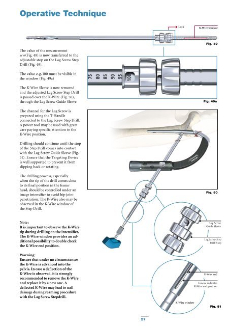
Operative Technique Lock K-Wire window Fig. 49 The value of the measurement ww(Fig. 48) is now transferred to the adjustable stop on the Lag Screw Step Drill (Fig. 49). The value e. g. 100 must be visible in the window (Fig. 49a) The K-Wire Sleeve is now removed and the adjusted Lag Screw Step Drill is passed over the K-Wire (Fig. 50), through the Lag Screw Guide Sleeve. Fig. 49a The channel for the Lag Screw is prepared using the T-Handle connected to the Lag Screw Step Drill. A power tool may be used with great care paying specific attention to the K-Wire position. Drilling should continue until the stop of the Step Drill comes into contact with the Lag Screw Guide Sleeve (Fig. 51). Ensure that the Targeting Device is well supported to prevent it from slipping back or rotating. The drilling process, especially when the tip of the drill comes close to its final position in the femur head, should be controlled under an image intensifier to avoid hip joint penetration. The K-Wire also may be observed in the K-Wire window of the Step Drill. Fig. 50 Note: It is important to observe the K-Wire tip during drilling on the intensifier. The K-Wire window provides an additional possibility to double check the K-Wire end position. Warning: Ensure that under no circumstances the K-Wire is advanced into the pelvis. In case a deflection of the K-Wire is observed, it is strongly recommended to remove the K-Wire and replace it by a new one. A deflected K-Wire may lead to nail damage during reaming procedure with the Lag Screw Stepdrill. K-Wire window Lag Screw Guide Sleeve Lag Screw Step Drill Stop K-Wire end Groove indicates K-Wire end position Fig. 51 27
- Page 1 and 2: Gamma3 Trochanteric Nail 180 Operat
- Page 3 and 4: Contents Introduction Design Featur
- Page 5 and 6: Features Design Features of the Gam
- Page 7 and 8: Implant Features Distal Locking Scr
- Page 9 and 10: Implant Features Fig. 7 Indications
- Page 11 and 12: Operative Technique Patient Positio
- Page 13 and 14: Operative Technique The C-Arm is tu
- Page 15 and 16: Operative Technique Alternative 1:
- Page 17 and 18: Operative Technique The Trocar is t
- Page 19 and 20: Operative Technique Assembly of Tar
- Page 21 and 22: Operative Technique Before checking
- Page 23 and 24: Operative Technique The Lag Screw s
- Page 25: Operative Technique Pre-Drilling th
- Page 29 and 30: Operative Technique Lag Screw Fixat
- Page 31 and 32: Operative Technique To verify the c
- Page 33 and 34: Operative Technique Distal Screw Lo
- Page 35 and 36: Operative Technique End Cap Inserti
- Page 37 and 38: Operative Technique Extraction of t
- Page 39 and 40: Operative Technique Dealing with Sp
- Page 41 and 42: Ordering Information - Instruments
- Page 43 and 44: Implants Packaging All implants are
- Page 45 and 46: Ordering Information - Implants Tro
- Page 47 and 48: Notes 47
Operative Technique<br />
Lock<br />
K-Wire window<br />
Fig. 49<br />
The value of the measurement<br />
ww(Fig. 48) is now transferred to the<br />
adjustable stop on the Lag Screw Step<br />
Drill (Fig. 49).<br />
The value e. g. 100 must be visible in<br />
the window (Fig. 49a)<br />
The K-Wire Sleeve is now removed<br />
and the adjusted Lag Screw Step Drill<br />
is passed over the K-Wire (Fig. 50),<br />
through the Lag Screw Guide Sleeve.<br />
Fig. 49a<br />
The channel for the Lag Screw is<br />
prepared using the T-Handle<br />
connected to the Lag Screw Step Drill.<br />
A power tool may be used with great<br />
care paying specific attention to the<br />
K-Wire position.<br />
Drilling should continue until the stop<br />
of the Step Drill comes into contact<br />
with the Lag Screw Guide Sleeve (Fig.<br />
51). Ensure that the Targeting Device<br />
is well supported to prevent it from<br />
slipping back or rotating.<br />
The drilling process, especially<br />
when the tip of the drill comes close<br />
to its final position in the femur<br />
head, should be controlled under an<br />
image intensifier to avoid hip joint<br />
penetration. The K-Wire also may be<br />
observed in the K-Wire window of<br />
the Step Drill.<br />
Fig. 50<br />
Note:<br />
It is important to observe the K-Wire<br />
tip during drilling on the intensifier.<br />
The K-Wire window provides an additional<br />
possibility to double check<br />
the K-Wire end position.<br />
Warning:<br />
Ensure that under no circumstances<br />
the K-Wire is advanced into the<br />
pelvis. In case a deflection of the<br />
K-Wire is observed, it is strongly<br />
recommended to remove the K-Wire<br />
and replace it by a new one. A<br />
deflected K-Wire may lead to nail<br />
damage during reaming procedure<br />
with the Lag Screw Stepdrill.<br />
K-Wire window<br />
Lag Screw<br />
Guide Sleeve<br />
Lag Screw Step<br />
Drill Stop<br />
K-Wire end<br />
Groove indicates<br />
K-Wire end position<br />
Fig. 51<br />
27


