Untitled - Stryker
Untitled - Stryker Untitled - Stryker
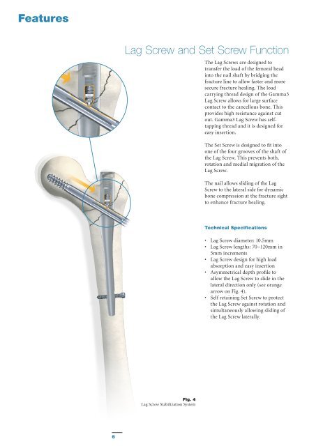
Features Lag Screw and Set Screw Function The Lag Screws are designed to transfer the load of the femoral head into the nail shaft by bridging the fracture line to allow faster and more secure fracture healing. The load carrying thread design of the Gamma3 Lag Screw allows for large surface contact to the cancellous bone. This provides high resistance against cut out. Gamma3 Lag Screw has selftapping thread and it is designed for easy insertion. The Set Screw is designed to fit into one of the four grooves of the shaft of the Lag Screw. This prevents both, rotation and medial migration of the Lag Screw. The nail allows sliding of the Lag Screw to the lateral side for dynamic bone compression at the fracture sight to enhance fracture healing. Technical Specifications • Lag Screw diameter: 10.5mm • Lag Screw lengths: 70−120mm in 5mm increments • Lag Screw design for high load absorption and easy insertion • Asymmetrical depth profile to allow the Lag Screw to slide in the lateral direction only (see orange arrow on Fig. 4). • Self retaining Set Screw to protect the Lag Screw against rotation and simultaneously allowing sliding of the Lag Screw laterally. Fig. 4 Lag Screw Stabilization System 6
Features Distal Locking Screws The distal Locking Screw has a short self-tapping tip which facilitates a faster and easier start as well as easy screw insertion. It helps to promote excellent surface to bone contact (Fig. 5). Technical Specifications • Distal Locking Screw Diameter: 5mm. • Distal Locking Screw lengths ranging from 25−50mm, in 2.5 and 5mm increments. Longer screws up to 120mm are available on request. • Fully threaded screw design. Partially treaded screws are available on request. • Self-tapping screw tip with optimized short cutting flutes. Fig. 5 • Optimized diameter under the head helps to prevent microfractures during insertion. The screw has an external diameter of 5mm, and provides an even higher fatigue strength than the clinically successful 6.28mm Locking Screw of the former generation of Gamma systems (data on file). Reduced diameter The screw diameter directly under the screw head has been reduced to prevent radial pressure that may cause micro fractures during screw insertion when the screw head reaches its final position. This reduction in diameter also improves the feel on the final tightening of the screw (Fig. 5a). Fig. 5a Length Definition of the Distal Locking Screw The distal Locking Screw is measured from head to tip (Fig. 5b). Length Definition 5mm Fig. 5b 7
- Page 2 and 3: Trochanteric Nail 180 Contributing
- Page 4 and 5: Introduction The Gamma3 Locking Nai
- Page 8 and 9: Features D d D > d Fig. 6 Gamma3 Sy
- Page 10 and 11: Operative Technique Pre-operative P
- Page 12 and 13: Operative Technique Incision Incisi
- Page 14 and 15: Operative Technique Incision Using
- Page 16 and 17: Operative Technique When reaming is
- Page 18 and 19: Operative Technique The Trocar is t
- Page 20 and 21: Operative Technique Alternative 4:
- Page 22 and 23: Operative Technique Assembly of Tar
- Page 24 and 25: Operative Technique Before checking
- Page 26 and 27: Operative Technique When the Gamma3
- Page 28 and 29: Operative Technique Lag Screw Inser
- Page 30 and 31: Operative Technique Warning: In the
- Page 32 and 33: Operative Technique Lag Screw Inser
- Page 34 and 35: Operative Technique Lag Screw Fixat
- Page 36 and 37: Operative Technique Alternative: Se
- Page 38 and 39: Operative Technique The Trocar is n
- Page 40 and 41: Operative Technique Nail Extension
- Page 42 and 43: Operative Technique Step IV (Fig. 6
- Page 44 and 45: Implants Packaging All implants are
- Page 46 and 47: Ordering Information - Implants TRO
- Page 48 and 49: Ordering Information - Instruments
- Page 50 and 51: References Publications More than 1
- Page 52: Stryker Trauma GmbH Prof.-Küntsche
Features<br />
Lag Screw and Set Screw Function<br />
The Lag Screws are designed to<br />
transfer the load of the femoral head<br />
into the nail shaft by bridging the<br />
fracture line to allow faster and more<br />
secure fracture healing. The load<br />
carrying thread design of the Gamma3<br />
Lag Screw allows for large surface<br />
contact to the cancellous bone. This<br />
provides high resistance against cut<br />
out. Gamma3 Lag Screw has selftapping<br />
thread and it is designed for<br />
easy insertion.<br />
The Set Screw is designed to fit into<br />
one of the four grooves of the shaft of<br />
the Lag Screw. This prevents both,<br />
rotation and medial migration of the<br />
Lag Screw.<br />
The nail allows sliding of the Lag<br />
Screw to the lateral side for dynamic<br />
bone compression at the fracture sight<br />
to enhance fracture healing.<br />
Technical Specifications<br />
• Lag Screw diameter: 10.5mm<br />
• Lag Screw lengths: 70−120mm in<br />
5mm increments<br />
• Lag Screw design for high load<br />
absorption and easy insertion<br />
• Asymmetrical depth profile to<br />
allow the Lag Screw to slide in the<br />
lateral direction only (see orange<br />
arrow on Fig. 4).<br />
• Self retaining Set Screw to protect<br />
the Lag Screw against rotation and<br />
simultaneously allowing sliding of<br />
the Lag Screw laterally.<br />
Fig. 4<br />
Lag Screw Stabilization System<br />
6


