Untitled - Stryker
Untitled - Stryker Untitled - Stryker
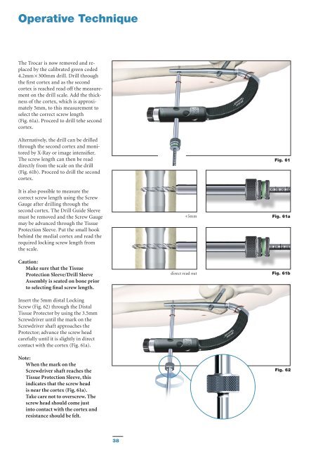
Operative Technique The Trocar is now removed and re - placed by the calibrated green coded 4.2mm × 300mm drill. Drill through the first cortex and as the second cortex is reached read off the measurement on the drill scale. Add the thickness of the cortex, which is approximately 5mm, to this measurement to select the correct screw length (Fig. 61a). Proceed to drill tehe second cortex. Alternatively, the drill can be drilled through the second cortex and monitored by X-Ray or image intensifier. The screw length can then be read directly from the scale on the drill (Fig. 61b). Proceed to drill the second cortex. It is also possible to measure the correct screw length using the Screw Gauge after drilling through the second cortex. The Drill Guide Sleeve must be removed and the Screw Gauge may be advanced through the Tissue Protection Sleeve. Put the small hook behind the medial cortex and read the required locking screw length from the scale. Caution: Make sure that the Tissue Protection Sleeve/Drill Sleeve Assembly is seated on bone prior to selecting final screw length. Insert the 5mm distal Locking Screw (Fig. 62) through the Distal Tissue Protector by using the 3.5mm Screwdriver until the mark on the Screwdriver shaft approaches the Protector; advance the screw head carefully until it is slightly in direct contact with the cortex (Fig. 61a). Note: When the mark on the Screwdriver shaft reaches the Tissue Protection Sleeve, this indicates that the screw head is near the cortex (Fig. 61a). Take care not to overscrew. The screw head should come just into contact with the cortex and resistance should be felt. +5mm direct read out Fig. 61 Fig. 61a Fig. 61b Fig. 62 38
Operative Technique End Cap Insertion It is recommended to use an End Cap to close the proximal part of the nail to prevent bone ingrowth. Leave the Screwdriver for the distal locking in place and remove the Nail Holding Screw using the Ball Tip Screwdriver, Spreading Screwdriver or Strike Plate. Load the End Cap (size 0) to one of the Screwdrivers and pass the assembly through the top of the Targeting Device down into the nail. Turn the handle clockwise until it stops mechanically. Remove the Screwdriver, the distal Screwdriver and the distal sleeves and remove the Targeting Device in cranial direction. Alternatively the End Cap could also be inserted free hand after removal of the Target Device. Fig. 63 End Cap assembly Fig. 64 Final Nail assembly 39
- Page 2 and 3: Trochanteric Nail 180 Contributing
- Page 4 and 5: Introduction The Gamma3 Locking Nai
- Page 6 and 7: Features Lag Screw and Set Screw Fu
- Page 8 and 9: Features D d D > d Fig. 6 Gamma3 Sy
- Page 10 and 11: Operative Technique Pre-operative P
- Page 12 and 13: Operative Technique Incision Incisi
- Page 14 and 15: Operative Technique Incision Using
- Page 16 and 17: Operative Technique When reaming is
- Page 18 and 19: Operative Technique The Trocar is t
- Page 20 and 21: Operative Technique Alternative 4:
- Page 22 and 23: Operative Technique Assembly of Tar
- Page 24 and 25: Operative Technique Before checking
- Page 26 and 27: Operative Technique When the Gamma3
- Page 28 and 29: Operative Technique Lag Screw Inser
- Page 30 and 31: Operative Technique Warning: In the
- Page 32 and 33: Operative Technique Lag Screw Inser
- Page 34 and 35: Operative Technique Lag Screw Fixat
- Page 36 and 37: Operative Technique Alternative: Se
- Page 40 and 41: Operative Technique Nail Extension
- Page 42 and 43: Operative Technique Step IV (Fig. 6
- Page 44 and 45: Implants Packaging All implants are
- Page 46 and 47: Ordering Information - Implants TRO
- Page 48 and 49: Ordering Information - Instruments
- Page 50 and 51: References Publications More than 1
- Page 52: Stryker Trauma GmbH Prof.-Küntsche
Operative Technique<br />
The Trocar is now removed and re -<br />
placed by the calibrated green coded<br />
4.2mm × 300mm drill. Drill through<br />
the first cortex and as the second<br />
cortex is reached read off the measurement<br />
on the drill scale. Add the thickness<br />
of the cortex, which is approximately<br />
5mm, to this measurement to<br />
select the correct screw length<br />
(Fig. 61a). Proceed to drill tehe second<br />
cortex.<br />
Alternatively, the drill can be drilled<br />
through the second cortex and monitored<br />
by X-Ray or image intensifier.<br />
The screw length can then be read<br />
directly from the scale on the drill<br />
(Fig. 61b). Proceed to drill the second<br />
cortex.<br />
It is also possible to measure the<br />
correct screw length using the Screw<br />
Gauge after drilling through the<br />
second cortex. The Drill Guide Sleeve<br />
must be removed and the Screw Gauge<br />
may be advanced through the Tissue<br />
Protection Sleeve. Put the small hook<br />
behind the medial cortex and read the<br />
required locking screw length from<br />
the scale.<br />
Caution:<br />
Make sure that the Tissue<br />
Protection Sleeve/Drill Sleeve<br />
Assembly is seated on bone prior<br />
to selecting final screw length.<br />
Insert the 5mm distal Locking<br />
Screw (Fig. 62) through the Distal<br />
Tissue Protector by using the 3.5mm<br />
Screwdriver until the mark on the<br />
Screwdriver shaft approaches the<br />
Protector; advance the screw head<br />
carefully until it is slightly in direct<br />
contact with the cortex (Fig. 61a).<br />
Note:<br />
When the mark on the<br />
Screwdriver shaft reaches the<br />
Tissue Protection Sleeve, this<br />
indicates that the screw head<br />
is near the cortex (Fig. 61a).<br />
Take care not to overscrew. The<br />
screw head should come just<br />
into contact with the cortex and<br />
resistance should be felt.<br />
+5mm<br />
direct read out<br />
Fig. 61<br />
Fig. 61a<br />
Fig. 61b<br />
Fig. 62<br />
38


