

Variax foot locking plate system - Stryker
Variax foot locking plate system - Stryker
Variax foot locking plate system - Stryker

Create successful ePaper yourself
Turn your PDF publications into a flip-book with our unique Google optimized e-Paper software.
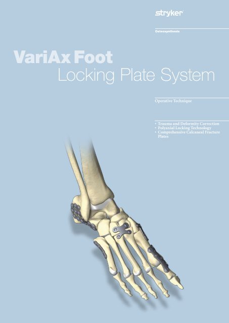
VariAx Foot<br />
Locking Plate System<br />
Operative Technique<br />
• Trauma and Deformity Correction<br />
• Polyaxial Locking Technology<br />
• Comprehensive Calcaneal Fracture<br />
Plates
Table of Contents<br />
1. Introduction 3<br />
2. Overview 5<br />
3. Indications and Contraindications 6<br />
4. General Operative Technique 7<br />
5. Ordering Information 17<br />
This Operative Technique sets forth<br />
detailed recommended procedures for<br />
using <strong>Stryker</strong> Osteosynthesis devices<br />
and instruments. It offers guidance<br />
that should be followed, but, as with<br />
any technical guide, each surgeon<br />
must consider the particular needs<br />
of each patient and make appropriate<br />
adjustments as required.<br />
2
Introduction<br />
The VariAx Foot Locking Plate System represents a new generation of implant<br />
technology for <strong>foot</strong> surgery. The reconstruction and fixation of bones in the<br />
<strong>foot</strong> can now be accomplished by means of the patented SmartLock polyaxial<br />
<strong>locking</strong> mechanism. This powerful feature allows a surgeon to insert polyaxial<br />
<strong>locking</strong> or non-<strong>locking</strong> screws at variable angles with respect to the <strong>plate</strong>, so that<br />
they can be targeted to address the location and geometry of a given fracture or<br />
osteotomy. Each <strong>plate</strong> can be configured with a combination of <strong>locking</strong> and/or<br />
non-<strong>locking</strong> screws which satisfy the intraoperative requirements of a particular<br />
case, without constraint or reliance on any pre-existing <strong>plate</strong> designs.<br />
Features and Benefits<br />
• Complete Plating System<br />
Multiple indication based <strong>plate</strong> designs are included in the VariAx Foot Locking<br />
Plate System, which are engineered to address specific <strong>foot</strong> trauma and deformity<br />
indications.<br />
• Polyaxial Drill Guide<br />
Allows placement of <strong>locking</strong> screws at a variable angle (up to ± 15°).<br />
• Low Profile Plate Design and Reduced Screw Head Prominence<br />
Each <strong>plate</strong> is designed to minimize soft tissue irritation by having a low profile<br />
design (1mm – 1.5mm thickness). Furthermore, the screws are designed to have<br />
minimal head prominence when fully inserted in a <strong>plate</strong>, which further reduces<br />
the risk of irritation.<br />
• Full-Range of 2.7mm and 3.5mm Locking and Non-Locking Screws<br />
Offers intraoperative solutions to cover a broad range of clinical situations.<br />
• Efficient T7 or T10 Screw Head Design<br />
All VariAx Foot Locking Plate System screws are designed with either a T7 head<br />
(for 2.7mm screws), or a T10 head (for 3.5mm screws). This screw head design<br />
facilitates efficient force transmission from the screwdriver blade to the screw,<br />
and reduces the risk of screw head stripping.<br />
• Anodization Type II<br />
Increases the strength of all VariAx Foot Plates, and may reduce the incidence of<br />
tissue adherence.<br />
• Two Dedicated Calcaneal Plate<br />
Designs<br />
The VariAx Foot Locking Plate<br />
System offers two distinct calcaneal<br />
<strong>plate</strong> designs, each incorporating<br />
a different design philosophy. The<br />
mesh design provides surgeons<br />
with an extremely low profile <strong>plate</strong><br />
that can be easily contoured, and<br />
has many screw placement options.<br />
The standard <strong>plate</strong> design provides<br />
surgeons with a strong <strong>plate</strong> that can<br />
be easily contoured to the superior<br />
surface of the calcaneus.<br />
3
Introduction<br />
• Patented Polyaxial Locking<br />
Technology<br />
Each screw is made of titanium alloy<br />
(Grade V), which is slightly harder<br />
than the <strong>plate</strong>s, which are made from<br />
commercially pure titanium (Grade<br />
II). When a <strong>locking</strong> screw is used, the<br />
thread in the head of the harder screw<br />
reshapes the softer titanium used in<br />
the <strong>plate</strong>, thus creating a secure formfitting<br />
geometry. This process results<br />
in a solid, locked connection between<br />
the head of the screw, and the <strong>plate</strong>.<br />
• Unique One-Step Locking<br />
Achieved by simply inserting a<br />
<strong>locking</strong> screw within the polyaxial<br />
<strong>locking</strong> range of ±15°, without the<br />
need for further steps.<br />
-15° +15°<br />
• Compression and Locking in One-<br />
Step<br />
As a screw is inserted and tightened<br />
into an oval compression hole,<br />
compression can be achieved. If a<br />
<strong>locking</strong> screw is used, the screw can<br />
then be locked into the <strong>plate</strong> in a<br />
single step.<br />
• Deluxe or Basic Configurations<br />
The VariAx Foot Locking Plate<br />
System is available in two renditions:<br />
a Deluxe configuration, and a Basic<br />
configuration. The Deluxe set<br />
contains every implant design, while<br />
the Basic set includes a selection with<br />
<strong>plate</strong>s most commonly needed for<br />
<strong>foot</strong> surgery.<br />
• Modular System Design<br />
The modular instrumentation <strong>system</strong><br />
is designed for seamless integration of<br />
other products from the <strong>Stryker</strong> Foot<br />
Solutions portfolio.<br />
• Color Coding of Instruments<br />
The instruments are color coded to<br />
facilitate ease-of-use during surgery.<br />
4<br />
The SmartLock Locking Technology is patented (US 6,322,562;<br />
DE 43 43 117; EP 1 143 867) by Professor Dietmar Wolter,<br />
Hamburg, Germany.
Overview<br />
Plate Options<br />
T-Plate<br />
Curved<br />
Plate<br />
Broad<br />
Straight Plate<br />
L-Plate<br />
Rectangular<br />
Plate<br />
Oblique<br />
T-Plate<br />
H-Plate<br />
3-D Plate<br />
Calcaneus Standard Plate<br />
Calcaneus Mesh Plate<br />
Screw Options<br />
2.7mm<br />
Locking<br />
2.7mm<br />
Non-<br />
Locking<br />
3.5mm<br />
Locking<br />
3.5mm<br />
Non-<br />
Locking<br />
Smaller <strong>plate</strong> holes fit 2.7mm screws<br />
Larger <strong>plate</strong> holes fit 3.5mm screws<br />
5
Indications<br />
The VariAx Foot Locking Plate System is indicated for use in internal fixation, reconstruction or arthrodeses of small bones,<br />
including those in the fore<strong>foot</strong>, mid<strong>foot</strong>, and hind<strong>foot</strong>. The physician’s education, training and professional judgment must<br />
be relied upon to choose the most appropriate device and treatment option.<br />
Examples of Applications<br />
• 1 st Metatarsal Phalangeal Joint<br />
(MPJ) Arthrodesis, with or without<br />
interpositional bone graft<br />
• Proximal Osteotomy of Metatarsals<br />
1 - 5<br />
• Lapidus Fusion<br />
• Lisfranc Arthrodesis<br />
• Isolated Lisfranc Arthrodesis,<br />
Metatarsal Cuneiform Joint (MCJ)<br />
1 - 5<br />
• Metatarsal Fractures<br />
• Talo-Navicular (TN) Arthrodesis<br />
• Calcaneal-Cuboid (CC) Arthrodesis<br />
• Calcaneus Fractures<br />
Relative Contraindications<br />
• Inadequate bone quantity and quality<br />
• Patients with active infections<br />
• Patients with metal allergies and<br />
foreign body sensitivity<br />
• Severely non-compliant patients with<br />
mental or neurological conditions<br />
who are unwilling or incapable<br />
of following postoperative care<br />
instructions<br />
• Patients with limited blood supply<br />
or insufficient quality or quantity of<br />
bone<br />
• Patients with unstable physical and/<br />
or mental health conditions<br />
The table below lists several common surgical <strong>foot</strong> indications, together with the VariAx Foot implants that are suggested to<br />
treat these indications.<br />
Examples of<br />
Applications<br />
Implant<br />
Curved Plate<br />
Oblique T-Plate<br />
3-D Plate<br />
Broad Straight Plate<br />
Rectangular Plate<br />
H-Plate<br />
L-Plate<br />
T-Plate<br />
Calcaneus Mesh Plate<br />
Calcaneus Standard Plate<br />
1 st MPJ Arthrodesis , with or without<br />
Interpositional Bone Graft<br />
x x x x x x<br />
Proximal Osteotomy of MT 1 - 5 x x x x<br />
Lapidus Fusion x x x x x x<br />
Lisfranc Arthrodesis x x<br />
Isolated Lisfranc Arthrodesis, MCJ 1-5 x x x x<br />
Metatarsal Fractures x x x x x x<br />
TN Arthrodesis x x<br />
CC Arthrodesis x x<br />
Calcaneal Fractures x x<br />
6
Operative Technique<br />
The Operative Technique listed below is designed to<br />
provide a general overview on the instruments and<br />
procedure required to implant a VariAx Foot Plate.<br />
Planning and Preparation<br />
Clear identification and classification of the fracture,<br />
osteotomy, or fusion site should first be established<br />
preoperatively using the appropriate methods and<br />
visualization. Appropriate surgical incisions are<br />
performed to expose the implantation site, and<br />
an osteotomy can then be performed if necessary.<br />
The Coughlin Reamer System can then be used to<br />
prepare the articular surfaces, prior to fixation with<br />
certain VariAx Foot Plates. Use the appropriate<br />
size of reamer according to the diameter of the joint<br />
surface.<br />
Optional: Joint Preparation in<br />
Metatarsophalangeal Arthrodesis using<br />
Coughlin Small Joint Reamers<br />
The convex phalangeal reamer is used to prepare a<br />
concave surface. The reamers are available in sizes<br />
10-18mm, however, it is important that the same<br />
sized metatarsal and phalangeal reamers are used. A<br />
1.4mm K-wire (45-80200) is driven into the center of<br />
the proximal phalanx, and advanced approximately<br />
1.5cm. The phalangeal reamer is placed over the<br />
K-wire, and the phalangeal surface is reamed<br />
creating a concave surface. The reamer and K-wire<br />
are then removed.<br />
Please note: Because the amount of reaming<br />
should be limited, apply low speed and be careful<br />
not to apply excessive pressure to avoid damage<br />
to the fusion surface. Provide cooling with saline<br />
irrigation. All reamers should be checked prior to<br />
use.<br />
A K-wire is then centered on the prepared metatarsal<br />
surface and driven in a proximal direction<br />
approximately 1.5cm. The same size barrel reamer<br />
is then placed over the K-wire, and the metatarsal<br />
metaphysis is reduced to a cylinder of constant<br />
dimension. The barrel reamer is removed, and<br />
debris and excess bone fragments are removed<br />
in a circumferential fashion. Adequate retraction<br />
of soft tissues is important throughout the joint<br />
preparation process. Finally, the same sized concave<br />
reamer is then used to prepare a convex surface to<br />
match the proximal phalanx.<br />
Joint Alignment<br />
By creating cup-shaped surfaces, any desired<br />
alignment may be achieved. The desired alignment<br />
is typically valgus of 15° to 20° and dorsiflexion of<br />
20° to 30° (in reference to the metatarsophalangeal<br />
axis and neutral rotation). The cup-shaped<br />
surfaces allow any one of these dimensions to be<br />
changed without altering another dimension. (For<br />
example, rotation may be changed without affecting<br />
dorsiflexion or valgus.)<br />
7
Operative Technique<br />
Stabilization, Provisional Plate<br />
Placement<br />
Establish primary stabilization of the<br />
fracture, osteotomy, or fusion site,<br />
using the included 1.4mm K-Wires<br />
(45-80200).<br />
VariAx Foot Plates can be removed<br />
from the <strong>plate</strong> tray and handled using<br />
the Forceps with Grasping Lips (64-<br />
20129). These forceps are designed<br />
to fit inside a single <strong>plate</strong> hole, and<br />
hold the <strong>plate</strong> in place by expanding<br />
and making contact with the inner<br />
circumference of the hole.<br />
Most VariAx Foot Plates include<br />
K-wire holes that are designed to<br />
accommodate 1.4mm Trocar Tipped<br />
K-wires, for use in temporarily<br />
stabilizing the <strong>plate</strong>s to bone.<br />
The K-Wire Cutting Pliers (45-80020)<br />
can be used to cut the K-Wires to<br />
the desired length. This instrument<br />
includes a silicon inlay which prevents<br />
the cut end of a K-Wire from being<br />
ejected from the instrument.<br />
Although some VariAx Foot Plates are<br />
pre-contoured, additional contouring<br />
of the <strong>plate</strong>s is possible using the Plate<br />
Bending Pliers (45-80010).<br />
Please note: excessive <strong>plate</strong> bending<br />
may lead to failure of the <strong>locking</strong><br />
mechanism, and is not recommended.<br />
The Plate Bending Pliers are designed<br />
to only be used in circular holes, and<br />
must not be used inside oval holes.<br />
8
Operative Technique<br />
Plate Hole Configurations<br />
Important:<br />
3.5 mm<br />
1. Each round screw hole in a VariAx<br />
Foot Plate is designed to accomodate<br />
a specific size of screw - the smaller<br />
holes accomodate 2.7mm screws, and<br />
the larger holes accomodate 3.5mm<br />
screws. These screws and holes are<br />
NOT interchangeable - a 3.5mm screw<br />
must not be used in a 2.7mm screw<br />
hole, and a 2.7mm screw must not be<br />
used in a 3.5mm screw hole.<br />
2.7 mm<br />
no lip<br />
compression hole<br />
lip<br />
lip<br />
compression hole<br />
no lip<br />
2. Some VariAx Foot Plates include<br />
oval <strong>locking</strong> compression holes, which<br />
are designed to accomodate a specific<br />
size of screw - the smaller oval holes<br />
accomodate 2.7mm screws, and the<br />
larger oval holes accomodate 3.5mm<br />
screws. These screws and holes are<br />
NOT interchangeable - a 3.5mm<br />
screw must not be used in a 2.7mm<br />
compression hole, and a 2.7mm<br />
screw must not be used in a 3.5mm<br />
compression hole.<br />
The oval holes allow for the active<br />
compression of different bone<br />
segments along the long axis of an oval<br />
hole. In a compression hole, a drill hole<br />
can be created in an eccentric position<br />
in the part of the oval hole that has<br />
no lip. As the screw is tightened, the<br />
screwhead glides into the area of the<br />
hole that has a lip. If a <strong>locking</strong> screw is<br />
used, the screw can then be locked into<br />
the <strong>plate</strong> in a single step.<br />
Please note: If the complete<br />
compression of two bone fragments<br />
takes place before a <strong>locking</strong> screw has<br />
been able to fully glide into the area<br />
of an oval <strong>locking</strong> hole that has a lip,<br />
<strong>locking</strong> may not be possible.<br />
9
Operative Technique<br />
Preparation for Screw Insertion<br />
A drill guide must first be placed into<br />
a corresponding <strong>plate</strong> screw hole (in a<br />
<strong>plate</strong>), prior to pre-drilling a pilot hole.<br />
The Drill Guide for Circular Locking<br />
Holes (45-80001) must be used in<br />
circular holes. This instrument has<br />
two ends: one end is designed only to<br />
be used when pre-drilling for 2.7mm<br />
screws (and is indicated with black<br />
lines), and the other end is designed<br />
only to be used when pre-drilling for<br />
3.5mm screws (and is indicated by<br />
yellow lines).<br />
The drill guide is designed to limit<br />
drilling to a ±15° angle with respect to<br />
the <strong>plate</strong>. Drilling at an angle greater<br />
then ±15° may prevent <strong>locking</strong> from<br />
taking place, and is not recommended.<br />
If drilling through an oval<br />
compression hole, the Drill Guide for<br />
Oval Compression Holes (45-80005)<br />
must be used. This drill guide has<br />
two ends: one end is designed only to<br />
be used when pre-drilling for 2.7mm<br />
screws (and is indicated with black<br />
lines), and the other end is designed<br />
only to be used when pre-drilling<br />
for 3.5mm screws (and is indicated<br />
by yellow lines). This drill guide is<br />
marked showing an eccentric position<br />
of the drill hole with respect to the<br />
<strong>plate</strong> screw hole.<br />
Compression is only possible in one<br />
direction, and the drill guide must<br />
be positioned such that the drill hole<br />
will be created on the side of the oval<br />
compression hole which does not have<br />
a <strong>locking</strong> lip.<br />
Note:<br />
Drill guides should always fit securely<br />
within a screw hole – a mismatch<br />
between the drill guide and the<br />
<strong>plate</strong> hole indicates that the wrong<br />
dimension drill guide has been<br />
chosen.<br />
The Drill Guide for Oval Compression<br />
Holes must be placed at a 90° angle to<br />
the <strong>plate</strong>, and cannot be angulated.<br />
10
Operative Technique<br />
Preparation for Screw Insertion<br />
Use the appropriate twist drill to<br />
create a pilot hole through the drill<br />
guide. The twist drills are color coded<br />
to match the color associated with the<br />
drill guide: the 2.7mm drill guide has<br />
a black line on it, which matches the<br />
black line on the 2.0mm Twist Drill<br />
(45-27010, which is used to pre-drill<br />
for 2.7mm screws). Similarly, the<br />
3.5mm drill guide has a yellow line<br />
on it, which matches the yellow line<br />
on the 2.6mm Twist Drill (45-35010,<br />
which is used to pre-drill for 3.5mm<br />
screws).<br />
Measure the depth of the predrilled<br />
hole using the appropriate depth<br />
gauge. For 2.7mm screw holes,<br />
use the Depth Measuring Gauge<br />
for 2.7mm Screws (45-27001). For<br />
3.5mm screw holes, use the Depth<br />
Measuring Gauge for 3.5mm Screws<br />
(45-35001). As with the twist drills<br />
and drill guides, the depth gauges<br />
are color-coded with black or yellow<br />
lines (to be used to measure 2.7mm or<br />
3.5mm screws, respectively). Always<br />
measure the depth of the predrilled<br />
hole by inserting the depth gauge first<br />
through the <strong>plate</strong>, and then into the<br />
predrilled hole. The depth gauges<br />
are designed to measure for bicortical<br />
screws only, and the hook of the depth<br />
gauge must be hooked onto the surface<br />
of the opposite cortex. The sleeve of<br />
the depth gauge must be fully inserted<br />
into the respective <strong>plate</strong> hole prior<br />
to measuring. Failure to measure<br />
without a <strong>plate</strong> will result in a false<br />
reading.<br />
Although the <strong>locking</strong> and non-<strong>locking</strong><br />
screws found in the VariAx Foot<br />
System are self-tapping, there may be<br />
certain circumstances when the use<br />
of a tap may be desired. For 2.7mm<br />
screw holes, use the Tap for 2.7mm<br />
Screws (45-27005), and for 3.5mm<br />
holes, use the Tap for 3.5mm Screws<br />
(45-35005). The taps are similarly<br />
color coded black (2.7mm), and yellow<br />
(3.5mm).<br />
11
Operative Technique<br />
Preparation for Screw Insertion<br />
Assemble the appropriate Screwdriver<br />
Blade (with AO fitting) with the Screwdriver<br />
Handle, Revolving/Rigid, AO<br />
(45-85000).<br />
Please note: the black coded Screwdriver<br />
Blade, AO, T7 (45-27015) is<br />
used to insert 2.7mm screws, and<br />
the yellow coded Screwdriver Blade,<br />
AO, T10 (45-35015) is used to insert<br />
3.5mm screws. Begin by pushing<br />
the AO quick-connect sleeve towards<br />
the body of the Screwdriver Handle,<br />
insert the screwdriver blade into the<br />
AO quick-connect coupling, and then<br />
release the sleeve.<br />
Holding sleeves for screws can be used<br />
to securely attach a screw to the screwdriver<br />
during screw insertion. The<br />
yellow coded Holding Sleeve for 3.5mm<br />
Screws (45-35030), and the black coded<br />
Holding Sleeve for 2.7mm Screws<br />
(45-27030) are used for 3.5mm, or<br />
2.7mm screws, respectively.<br />
Assemble the appropriate holding<br />
sleeve and slide it over the screwdriver<br />
until it engages, as shown.<br />
Push the holding sleeve back so that the<br />
tip of the screwdriver becomes visible.<br />
Engage the screwdriver tip with the<br />
head of the chosen screw, then push<br />
the Holding Sleeve forward, as shown.<br />
The holding sleeve will engage with the<br />
head of the screw, firmly holding it in<br />
place. The screw can then be removed<br />
securely from the screw rack, and the<br />
screw can be inserted into the <strong>plate</strong>.<br />
12
Operative Technique<br />
Screw Insertion<br />
Insert the screw into the predrilled<br />
hole using the screwdriver assembly.<br />
Prior to final tightening, as the screw<br />
head approaches the <strong>plate</strong>, draw the<br />
holding sleeve back from the screw<br />
head, and remove the screwdriver<br />
from the screw. Final tightening is not<br />
recommended until all desired screws<br />
have been provisionally inserted into<br />
a <strong>plate</strong>.<br />
Repeat drilling, measuring, and<br />
placement of <strong>locking</strong> or non-<strong>locking</strong><br />
screws in the remaining holes, as<br />
required. Always remember to use the<br />
appropriate sized drill guide.<br />
Final Tightening<br />
The highly efficient T7 interface (for<br />
2.7mm screws) and T10 interface (for<br />
3.5mm screws) facilitates effective<br />
transmission of torque from the<br />
screwdriver blade to the screw.<br />
Accordingly, applying excessive<br />
torque during screw insertion is not<br />
recommended, and may result in<br />
damage to the screwdriver blade.<br />
13
Final Tightening<br />
To limit the the amount of torque<br />
that is applied during final tightening,<br />
we recommend using a “two finger<br />
technique”, as illustrated.<br />
Gripping the handle firmly within<br />
the whole hand, as illustrated, is<br />
not recommended, as an excessive<br />
amount of torque can be applied.<br />
Note:<br />
The screwdriver handle contains a<br />
switch which allows the metal and<br />
plastic segments of the handle to<br />
either independently rotate, or to<br />
be rigidly locked together. When<br />
performing final tightening, the<br />
switch on the screwdriver handle<br />
must be in the fully-locked position<br />
(in which the position of the switch<br />
is closest to the base of the handle).<br />
Using two finger tightening, final<br />
tightening of all the screws can then<br />
be performed.<br />
Please note that the screw head does<br />
not need to be completely flush with<br />
the <strong>plate</strong> to be securely locked. The<br />
screw will be securely locked within<br />
the <strong>plate</strong> by using the two finger<br />
tightening technique, as described<br />
above.<br />
14
Operative Technique<br />
Final Tightening<br />
Note:<br />
Following final tightening, VariAx<br />
Locking Screws can be removed and<br />
repositioned at a different angle<br />
in the same hole up to a maximum<br />
of three times. Attempting to<br />
reposition a VariAx Locking screw in<br />
a hole that has already been locked<br />
three times is not recommended.<br />
Verify proper placement of screws by<br />
use of fluoroscopy to ensure that there<br />
is no penetration of joint spaces.<br />
15
Operative Technique<br />
Optional: Washers<br />
VariAx Foot non-<strong>locking</strong> screws can<br />
also be used as independent implants,<br />
separate from a <strong>plate</strong>. If indicated,<br />
non-<strong>locking</strong> screws can also be used<br />
together with a washer, to increase<br />
the surface contact area between the<br />
head of a screw, and bone. For 3.5mm<br />
screws, use a Washer for 3.5mm Screws<br />
(40-35900), and for 2.7mm screws, use<br />
a Washer for 2.7mm Screws (40-27900).<br />
16
Ordering Information<br />
3.5mm LOCKING SCREWS<br />
Quantity per Quantity per<br />
REF Description Basic Set Deluxe Set<br />
40-35610 Locking Screw, T10, 3.5x10mm 5 4<br />
40-35612 Locking Screw, T10, 3.5x12mm 5 4<br />
40-35614 Locking Screw, T10, 3.5x14mm 5 4<br />
40-35616 Locking Screw, T10, 3.5x16mm 5 4<br />
40-35618 Locking Screw, T10, 3.5x18mm 5 4<br />
40-35620 Locking Screw, T10, 3.5x20mm 5 4<br />
40-35622 Locking Screw, T10, 3.5x22mm 5 4<br />
40-35624 Locking Screw, T10, 3.5x24mm 5 4<br />
40-35626 Locking Screw, T10, 3.5x26mm 5 4<br />
40-35628 Locking Screw, T10, 3.5x28mm 5 4<br />
40-35630 Locking Screw, T10, 3.5x30mm 0 4<br />
40-35632 Locking Screw, T10, 3.5x32mm 0 4<br />
40-35634 Locking Screw, T10, 3.5x34mm 0 4<br />
40-35636 Locking Screw, T10, 3.5x36mm 0 4<br />
40-35638 Locking Screw, T10, 3.5x38mm 0 4<br />
40-35640 Locking Screw, T10, 3.5x40mm 0 4<br />
40-35642 Locking Screw, T10, 3.5x42mm 0 4<br />
40-35644 Locking Screw, T10, 3.5x44mm 0 4<br />
40-35646 Locking Screw, T10, 3.5x46mm 0 4<br />
40-35648 Locking Screw, T10, 3.5x48mm 0 4<br />
40-35650 Locking Screw, T10, 3.5x50mm 0 4<br />
40-35655 Locking Screw, T10, 3.5x55mm 0 4<br />
40-35660 Locking Screw, T10, 3.5x60mm 0 4<br />
40-35665 Locking Screw, T10, 3.5x65mm 0 4<br />
40-35670 Locking Screw, T10, 3.5x70mm 0 4<br />
2.7mm LOCKING SCREWS<br />
Quantity per Quantity per<br />
REF Description Basic Set Deluxe Set<br />
40-27608 Locking Screw, T7, 2.7x8mm 0 4<br />
40-27610 Locking Screw, T7, 2.7x10mm 5 4<br />
40-27612 Locking Screw, T7, 2.7x12mm 5 4<br />
40-27614 Locking Screw, T7, 2.7x14mm 5 4<br />
40-27616 Locking Screw, T7, 2.7x16mm 5 4<br />
40-27618 Locking Screw, T7, 2.7x18mm 5 4<br />
40-27620 Locking Screw, T7, 2.7x20mm 5 4<br />
40-27622 Locking Screw, T7, 2.7x22mm 5 4<br />
40-27624 Locking Screw, T7, 2.7x24mm 5 4<br />
40-27626 Locking Screw, T7, 2.7x26mm 5 4<br />
40-27628 Locking Screw, T7, 2.7x28mm 5 4<br />
40-27630 Locking Screw, T7, 2.7x30mm 0 4<br />
40-27632 Locking Screw, T7, 2.7x32mm 0 4<br />
40-27634 Locking Screw, T7, 2.7x34mm 0 4<br />
40-27636 Locking Screw, T7, 2.7x36mm 0 4<br />
40-27638 Locking Screw, T7, 2.7x38mm 0 4<br />
40-27640 Locking Screw, T7, 2.7x40mm 0 4<br />
40-27645 Locking Screw, T7, 2.7x45mm 0 4<br />
40-27650 Locking Screw, T7, 2.7x50mm 0 4<br />
17
Ordering Information<br />
3.5mm NON-LOCKING SCREWS<br />
Quantity per Quantity per<br />
REF Description Basic Set Deluxe Set<br />
40-35010 Bone Screw, T10, 3.5x10mm 3 4<br />
40-35012 Bone Screw, T10, 3.5x12mm 3 4<br />
40-35014 Bone Screw, T10, 3.5x14mm 3 4<br />
40-35016 Bone Screw, T10, 3.5x16mm 3 4<br />
40-35018 Bone Screw, T10, 3.5x18mm 3 4<br />
40-35020 Bone Screw, T10, 3.5x20mm 3 4<br />
40-35022 Bone Screw, T10, 3.5x22mm 3 4<br />
40-35024 Bone Screw, T10, 3.5x24mm 3 4<br />
40-35026 Bone Screw, T10, 3.5x26mm 3 4<br />
40-35028 Bone Screw, T10, 3.5x28mm 3 4<br />
40-35030 Bone Screw, T10, 3.5x30mm 0 4<br />
40-35032 Bone Screw, T10, 3.5x32mm 0 4<br />
40-35034 Bone Screw, T10, 3.5x34mm 0 4<br />
40-35036 Bone Screw, T10, 3.5x36mm 0 4<br />
40-35038 Bone Screw, T10, 3.5x38mm 0 4<br />
40-35040 Bone Screw, T10, 3.5x40mm 0 4<br />
40-35042 Bone Screw, T10, 3.5x42mm 0 4<br />
40-35044 Bone Screw, T10, 3.5x44mm 0 4<br />
40-35046 Bone Screw, T10, 3.5x46mm 0 4<br />
40-35048 Bone Screw, T10, 3.5x48mm 0 4<br />
40-35050 Bone Screw, T10, 3.5x50mm 0 4<br />
40-35055 Bone Screw, T10, 3.5x55mm 0 4<br />
40-35060 Bone Screw, T10, 3.5x60mm 0 4<br />
40-35065 Bone Screw, T10, 3.5x65mm 0 4<br />
40-35070 Bone Screw, T10, 3.5x70mm 0 4<br />
2.7mm NON-LOCKING SCREWS<br />
Quantity per Quantity per<br />
REF Description Basic Set Deluxe Set<br />
40-27008 Bone Screw, T7, 2.7x8mm 0 4<br />
40-27010 Bone Screw, T7, 2.7x10mm 3 4<br />
40-27012 Bone Screw, T7, 2.7x12mm 3 4<br />
40-27014 Bone Screw, T7, 2.7x14mm 3 4<br />
40-27016 Bone Screw, T7, 2.7x16mm 3 4<br />
40-27018 Bone Screw, T7, 2.7x18mm 3 4<br />
40-27020 Bone Screw, T7, 2.7x20mm 3 4<br />
40-27022 Bone Screw, T7, 2.7x22mm 3 4<br />
40-27024 Bone Screw, T7, 2.7x24mm 3 4<br />
40-27026 Bone Screw, T7, 2.7x26mm 3 4<br />
40-27028 Bone Screw, T7, 2.7x28mm 3 4<br />
40-27030 Bone Screw, T7, 2.7x30mm 0 4<br />
40-27032 Bone Screw, T7, 2.7x32mm 0 4<br />
40-27034 Bone Screw, T7, 2.7x34mm 0 4<br />
40-27036 Bone Screw, T7, 2.7x36mm 0 4<br />
40-27038 Bone Screw, T7, 2.7x38mm 0 4<br />
40-27040 Bone Screw, T7, 2.7x40mm 0 4<br />
40-27045 Bone Screw, T7, 2.7x45mm 0 4<br />
40-27050 Bone Screw, T7, 2.7x50mm 0 4<br />
18
Ordering Information<br />
PLATES Quantity per Quantity per<br />
REF Description Basic Set Deluxe Set<br />
40-15011 Curved Plate, 4 holes 2 2<br />
40-15012 Curved Plate, 5 holes, Right 2 2<br />
40-15013 Curved Plate, 5 holes, Left 2 2<br />
40-15014 Curved Plate, 6 holes 2 2<br />
40-15021 H-Plate, Small 0 2<br />
40-15022 H-Plate, Medium 0 2<br />
40-15023 H-Plate, Large 0 2<br />
40-15031 Rectangular Compression Plate, size 1 0 2<br />
40-15032 Rectangular Locking Plate, size 2 0 2<br />
40-15033 Rectangular Compression Plate, size 2 2 2<br />
40-15041 Broad Straight Plate, Short 0 2<br />
40-15042 Broad Straight Plate, Medium 0 2<br />
40-15043 Broad Straight Plate, Long 0 2<br />
40-15061 3-D Plate, Left 2 2<br />
40-15062 3-D Plate, Right 2 2<br />
40-15071 Oblique T-Plate, Left 2 2<br />
40-15072 Oblique T-Plate, Right 2 2<br />
40-15081 T-Plate 0 2<br />
40-15091 L-Plate, Left 2 2<br />
40-15092 L-Plate, Right 2 2<br />
40-10102 Calcaneus Mesh Plate, Small 0 2<br />
40-10104 Calcaneus Mesh Plate, Medium 0 2<br />
40-10106 Calcaneus Mesh Plate, Large 0 2<br />
40-10112 Calcaneus Standard Plate, Small 0 2<br />
40-10114 Calcaneus Standard Plate, Medium 0 2<br />
40-10116 Calcaneus Standard Plate, Large 0 2<br />
19
Ordering Information<br />
Quantity per Quantity per<br />
REF Description Basic Set Deluxe Set<br />
Instruments<br />
45-27005 Tap for 2.7mm Screws, AO, 50mm 1 1<br />
45-35005 Tap for 3.5mm Screws, AO, 70mm 1 1<br />
45-27001 Depth Measuring Gauge for 2.7mm Screws 1 1<br />
45-35001 Depth Measuring Gauge for 3.5mm Screws 1 1<br />
45-80001 Drill Guide for Circular Locking Holes 1 1<br />
45-80005 Drill Guide for Oval Compression Holes 1 1<br />
45-27015 Screwdriver Blade, AO, T7 2 2<br />
45-35015 Screwdriver Blade, AO, T10 2 2<br />
45-85000 Screwdriver Handle, Revolving/Rigid, AO 2 2<br />
45-35030 Holding Sleeve for 3.5mm screws 1 1<br />
45-27030 Holding Sleeve for 2.7mm screws 1 1<br />
45-80010 Plate Bending Pliers 2 2<br />
45-80020 K-Wire Cutting Pliers (max 1.6mm) 1 1<br />
64-20129 Forceps with Grasping Lips 1 1<br />
Twist Drills<br />
45-27010 Drill, 2.0mm x 102mm, WL50mm, AO-Shaft 2 2<br />
45-35010 Drill, 2.6mm x 122mm, WL70mm, AO-Shaft 2 2<br />
Optional Instruments<br />
45-80030 Joint Distraction Forceps 0 optional<br />
29-13462 Accessory Tray optional optional<br />
20
Ordering Information<br />
WASHERS<br />
Quantity per Quantity per<br />
REF Description Basic Set Deluxe Set<br />
40-35900 Washer for 3.5mm screw 0 10<br />
40-27900 Washer for 2.7mm screw 0 10<br />
K-WIRES & STEINMANN PINS<br />
Quantity per Quantity per<br />
REF Description Basic Set Deluxe Set<br />
45-80100 K-Wire, Fully Threaded, 1.6mm x 200mm 4 4<br />
45-80200 K-Wire, Smooth, 1.4mm x 100mm 4 4<br />
45-80300 Steinmann Pin, Smooth, 2.5mm x 100mm 0 optional<br />
TWIST DRILLS Quantity per Quantity per<br />
REF Description Basic Set Deluxe Set<br />
45-27010 Drill, 2.0mm x 102mm, WL50mm, AO-Shaft 2 2<br />
45-35010 Drill, 2.6mm x 122mm, WL70mm, AO-Shaft 2 2<br />
Coughlin Small Joint Reamers<br />
Quantity per Diameter<br />
REF Type of Reamer Set (mm)<br />
6514-7-210 Concave 1 10<br />
6514-7-212 Concave 1 12<br />
6514-7-214 Concave 1 14<br />
6514-7-216 Concave 1 16<br />
6514-7-218 Concave 1 18<br />
6514-7-310 Convex 1 10<br />
6514-7-312 Convex 1 12<br />
6514-7-314 Convex 1 14<br />
6514-7-316 Convex 1 16<br />
6514-7-318 Convex 1 18<br />
6514-7-410 Barrel 1 10<br />
6514-7-412 Barrel 1 12<br />
6514-7-414 Barrel 1 14<br />
6514-7-416 Barrel 1 16<br />
6514-7-418 Barrel 1 18<br />
45-80200 K-Wire, Smooth, 1.4mm x 100mm 4<br />
29-33400 Coughlin Reamer Tray 1<br />
29-32401 Generic <strong>Stryker</strong> Foot Solutions Lid 1<br />
Note: The Coughlin Reamer tray does not fit inside the Basic Set configuration; it only fits inside the Deluxe Set configuration (the 4-Level Foot Solutions<br />
container with the VariAx Foot modules) if and only if no other modules are included. If other modules are included, the generic lid is required.<br />
21
Ordering Information<br />
Quantity per Quantity per<br />
REF Description Basic Set Deluxe Set<br />
Modules And Trays<br />
29-35000 Sterilization Container, 3 levels 1 0<br />
29-13009 Sterilization Container, 4 levels 0 1<br />
29-35200 <strong>Stryker</strong> Foot Container Lid - Half Size 1 1<br />
29-31400 VariAx Foot Instrument Tray 1 1<br />
29-31007 Drawer for Screw Racks 0 1<br />
29-31000 Deluxe Plate Module (includes Lid) 0 1<br />
29-31021 Inlay for Recon and Trauma Plates 0 1<br />
29-31022 Inlay for Calcaneus Plates 0 1<br />
29-31004 Screw Rack for 3.5 Locking Screws (includes Lid) 0 1<br />
29-31005 Screw Rack for 3.5 Bone Screws (includes Lid) 0 1<br />
29-31006 Screw Rack for 2.7 Screws (includes Lid) 0 1<br />
29-31050 Basic Plate Module (includes Lid) 1 0<br />
29-31052 Inlay 1 for Basic Plate Module 1 0<br />
29-31053 Inlay 2 for Basic Plate Module 1 0<br />
29-50000 Inlay Generic 0 1<br />
Miscellaneous<br />
45-80000 Spring for Holding Sleeve 0 0<br />
29-31013 Lid for Screw Rack 0 0<br />
29-31012 Lid for Deluxe Plate Module 0 0<br />
29-31051 Lid for Basic Plate Module 0 0<br />
22
Notes<br />
23
<strong>Stryker</strong> Leibinger GmbH & Co. KG<br />
Bötzinger Strasse 39-41<br />
D-79111 Freiburg<br />
Germany<br />
www.osteosynthesis.stryker.com<br />
This document is intended solely for the use of healthcare professionals. A surgeon must always rely on his or her<br />
own professional clinical judgment when deciding whether to use a particular product when treating a particular<br />
patient. <strong>Stryker</strong> does not dispense medical advice and recommends that surgeons be trained in the use of any particular<br />
product before using it in surgery. The information presented in this brochure is intended to demonstrate a <strong>Stryker</strong><br />
product. Always refer to the package insert, product label and/or user instructions including the instructions for<br />
Cleaning and Sterilization (if applicable) before using any <strong>Stryker</strong> products. Products may not be available in all<br />
markets. Product availability is subject to the regulatory or medical practices that govern individual markets. Please<br />
contact your <strong>Stryker</strong> representative if you have questions about the availability of <strong>Stryker</strong> products in your area.<br />
<strong>Stryker</strong> Corporation or its divisions or other corporate affiliated entities own, use or have applied for the following<br />
trademarks or service marks: <strong>Stryker</strong>, SmartLock, VariAx.<br />
All other trademarks are trademarks of their respective owners or holders.<br />
The products listed above are CE marked.<br />
Literature Number: 90-07805<br />
LOT C4608<br />
Copyright © 2009 <strong>Stryker</strong>


