

T2 GTN Operative Technique - Stryker
T2 GTN Operative Technique - Stryker
T2 GTN Operative Technique - Stryker

You also want an ePaper? Increase the reach of your titles
YUMPU automatically turns print PDFs into web optimized ePapers that Google loves.
Femur<br />
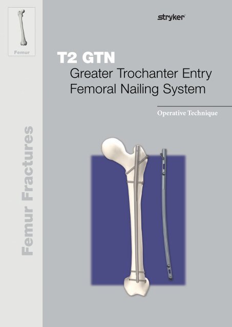
<strong>T2</strong> <strong>GTN</strong><br />
KnifeLight Greater Trochanter Entry<br />
Carpal Tunnel Ligament Release<br />
Femoral Nailing System<br />
<strong>Operative</strong> <strong>Technique</strong><br />
<strong>Operative</strong> <strong>Technique</strong><br />
Femur Fractures
Femoral Nailing System<br />
Contributing Surgeons<br />
Prof. Dr. med. Volker Bühren<br />
Chief of Surgical Services<br />
Medical Director of Murnau Trauma Center<br />
Murnau, Germany<br />
Joseph D. DiCicco III, D. O.<br />
Director Orthopaedic Trauma Service<br />
Good Samaritan Hospital<br />
Dayton, Ohio<br />
Associate Clinical Professor of Orthopaedic Surgery<br />
Ohio University and Wright State University<br />
USA<br />
Anthony T. Sorkin, M.D.<br />
Rockford Orthopaedic Associates, LLP, Clinical Instructor,<br />
Department of Surgery University of Illinois,<br />
College of Medicine Director,<br />
Orthopaedic Traumatology Rockford Memorial Hospital<br />
Rockford, Illinois,<br />
USA<br />
This publication sets forth detailed<br />
recommended procedures for using<br />
<strong>Stryker</strong> Osteosynthesis devices and<br />
instruments.<br />
It offers guidance that you should<br />
heed, but, as with any such technical<br />
guide, each surgeon must consider<br />
the particular needs of each patient<br />
and make appropriate adjustments<br />
when and as required.<br />
A workshop training is recommended<br />
prior to first surgery.<br />
All non-sterile devices must be<br />
cleaned and sterilized before use.<br />
Follow the instructions provided in<br />
our reprocessing guide (L24002000).<br />
Multi-component instruments must<br />
be disassembled for cleaning. Please<br />
refer to the corresponding assembly/<br />
disassembly instructions.<br />
See package insert (L22000023) for<br />
a complete list of potential adverse<br />
effects, contraindications, warnings<br />
and precautions. The surgeon must<br />
discuss all relevant risks, including<br />
the finite lifetime of the device, with<br />
the patient, when necessary.<br />
2<br />
Warning:<br />
Fixation Screws<br />
<strong>Stryker</strong> Osteosynthesis bone<br />
screws are not approved or intended<br />
for screw attachment or<br />
fixation to the posterior elements<br />
(pedicles) of the cervical, thoracic<br />
or lumbar spine.
Contents<br />
Page<br />
1. Introduction 4<br />
Implant Features 4<br />
Instrument Features 6<br />
References 6<br />
2. Indications, Precautions & Contraindications 7<br />
3. Additional Information 8<br />
Locking Options 8<br />
4. Pre-operative Planning 9<br />
5. <strong>Operative</strong> <strong>Technique</strong> 10<br />
Patient Positioning 10<br />
Incision 10<br />
Entry Point 11<br />
Unreamed <strong>Technique</strong> 12<br />
Reamed <strong>Technique</strong> 12<br />
Nail Selection 14<br />
Guided Locking Mode (via Target Device) 15<br />
Nail Insertion 16<br />
Static Locking Mode 18<br />
Freehand Distal Locking 20<br />
End Cap Insertion 21<br />
Dynamic Locking Mode 22<br />
External Apposition / Compression Mode 23<br />
Internal Apposition / Compression Mode 25<br />
Nail Removal 26<br />
Ordering Information – Implants 27<br />
Ordering Information – Instruments 30<br />
3
Introduction<br />
Introduction<br />
Over the past several decades antegrade<br />
femoral nailing has become<br />
the treatment of choice for most<br />
femoral shaft fractures.<br />
The <strong>T2</strong> <strong>GTN</strong> System is one of the first<br />
femoral nailing systems to offer an<br />
option for tip of greater trochanteric<br />
entry point insertion with the option<br />
to apply compression either by an<br />
external compression device or by an<br />
internal compression screw.<br />
Through the development of a<br />
common, streamlined and intuitive<br />
surgical approach the <strong>T2</strong> <strong>GTN</strong> System<br />
offers the potential for more efficient<br />
treatment of fractures as well as<br />
simplifying the training requirements<br />
for all personnel involved.<br />
Implant Features<br />
The <strong>T2</strong> <strong>GTN</strong> Nailing System is the<br />
realization of excellent biomechanical<br />
intramedullary stabilization using<br />
small caliber, strong, cannulated<br />
implants for internal fixation of the<br />
femur. According to the fracture<br />
type, the system offers the option of<br />
different locking modes. In addition<br />
to static locking, a controlled<br />
dynamization with rotational stability<br />
is an option.<br />
In some indications, a controlled<br />
apposition/compression of bone<br />
fragments can be applied by attaching<br />
an external compression device to the<br />
top of a shaft screw inserted in the<br />
oblong hole. Alternatively, an internal<br />
Compression Screw can be introduced<br />
from the top of the nail. To further<br />
help increase rotational stability, the<br />
nail can be locked statically after<br />
using the controlled dynamization<br />
and apposition/compression option.<br />
When compression is applied the<br />
Partially Threaded Locking Screw<br />
(Shaft Screw) that has been placed<br />
in the oblong hole is drawing<br />
either the distal or the proximal<br />
segment towards the fracture site.<br />
In stable fractures, this offers the<br />
biomechanical advantage of creating<br />
active circumferential compression<br />
to the fracture site, transferring axial<br />
load to the bone, and reducing the<br />
function of the nail as a load bearing<br />
device (1).<br />
The beneficial effect of apposition/<br />
compression in treating long bone<br />
fractures in cases involving transverse<br />
and short oblique fractures that are<br />
axially stable is well documented<br />
(3, 4).<br />
Common 5mm cortical screws*<br />
simplify the surgical procedure<br />
and promote a minimally invasive<br />
approach. Fully Threaded Locking<br />
Screws are available for regular<br />
locking procedures. Partially<br />
Threaded Locking Screws (Shaft<br />
Screws) are designed to apply<br />
apposition/compression.<br />
A Cannulated Compression Screw to<br />
close the fracture site and End Caps<br />
are available in various sizes to allow<br />
an improved fit.<br />
All implants of the <strong>T2</strong> Nailing Systems<br />
are made of Type II anodized titanium<br />
alloy (Ti6AL4V) for enhanced<br />
biomechanical and biomedical<br />
performance**.<br />
See the detailed chart on the next page<br />
for the design specifications and size<br />
offerings.<br />
This ability to transfer load back to<br />
the bone may reduce the incidence of<br />
implant failure secondary to fatigue.<br />
Typical statically locked nails function<br />
as load bearing devices, and failure<br />
rates in excess of 20 % have been<br />
reported (2).<br />
* Special order 8mm <strong>T2</strong> Femoral Nails can only<br />
be locked with 4mm Fully Threaded screws at<br />
the nondriving end. As with all diameters of <strong>T2</strong><br />
Femoral Nails, the screws for driving end locking<br />
are 5mm.<br />
4<br />
** Axel Baumann, Nils Zander, Ti6Al4V with<br />
Anodization Type II: Biological Behaviour and<br />
Biomechanical Effects, White Paper, March 2005.
Introduction<br />
Nails<br />
Diameter<br />
Sizes<br />
8−15mm* (8,14 and 15mm nails are special order)<br />
Ø8-15mm: 240−480mm****<br />
5.0mm Partially Threaded Locking<br />
Screws (Shaft Screws)<br />
L = 25−120mm<br />
5.0mm Fully Threaded<br />
Locking Screws<br />
L = 25−120mm<br />
Note:<br />
Screw length is measured<br />
from top of head to tip.<br />
end Caps <strong>GTN</strong> **<br />
0mm +5mm +10mm +15mm<br />
Cannulated<br />
Compression Screw<br />
* 8mm nails require 4mm Fully<br />
Threaded Screws for Distal Locking<br />
end Caps <strong>T2</strong> ***<br />
** Cannot be used when the internal<br />
compression screw is applied<br />
*** To be used when the Cannulated<br />
Compression Screw is applied<br />
Standard +5mm<br />
+10mm +15mm<br />
**** Check with your local<br />
representative regarding<br />
availability of implant sizes<br />
5
Introduction<br />
Instrument Features<br />
A major advantage of the instrument<br />
system is a breakthrough in the<br />
integration of the instrument platform<br />
which can be used for the complete<br />
<strong>T2</strong> Nailing System, thereby helping to<br />
reduce complexity and inventory.<br />
The instrument platform offers<br />
advanced precision and usability, and<br />
features ergonomically styled targeting<br />
devices.<br />
Symbol coding on the instruments<br />
indicates the type of procedure, and<br />
dissimilar instruments must not be<br />
mixed.<br />
Symbol<br />
Square = Long instruments<br />
Triangular = Short instruments<br />
Drills<br />
Drills feature color coded rings :<br />
4.2mm = Green<br />
For 5.0mm Fully Threaded Locking<br />
Screws and for the second cortex<br />
when using 5.0mm Partially Threaded<br />
Locking Screws (Shaft Screws).<br />
5.0mm = Black<br />
For the first cortex when using 5.0mm<br />
Partially Threaded Locking Screws<br />
(Shaft Screws).<br />
References<br />
1.<br />
2.<br />
T. E. Richardson, M. Voor,<br />
D. Seligson, Fracture Site<br />
Compression and Motion with<br />
Three Types of Intramedullary<br />
Fixation of the Femur,<br />
Osteosynthese International (1998),<br />
6: 261-264<br />
Hutson et al., Mechanical<br />
Failures of Intramedullary Tibial<br />
Nails Applied without Reaming,<br />
Clin. Orthop. (1995), 315: 129-137<br />
3.<br />
4.<br />
5.<br />
M.E. Müller, et al., Manual of<br />
Internal Fixation, Springer-Verlag,<br />
Berlin, 1991<br />
O. Gonschorek, G. O. Hofmann,<br />
V. Bühren, Interlocking<br />
Compression Nailing: a Report on<br />
402 Applications. Arch. Orthop.<br />
Trauma Surg (1998), 117: 430-437<br />
Mehdi Mousavi, et al., Pressure<br />
Changes During Reaming with<br />
Different Parameters and Reamer<br />
Designs, Clinical Orthopaedics<br />
and Related Research, Number<br />
373, pp. 295-303, 2000<br />
6.<br />
7.<br />
Axel Baumann, Nils Zander,<br />
Ti6Al4V with Anodization Type<br />
II: Biological Behaviour and<br />
Biomechanical Effects, White<br />
Paper, March 2005.<br />
Jan Paul M. Frolke, et al. ;<br />
Intramedullary Pressure in<br />
Reamed Femoral Nailing with Two<br />
Different Reamer Designs., Eur. J.<br />
of Trauma, 2001 #5<br />
6
Indications, Precautions & Contraindications<br />
Indications<br />
• Open and closed femoral fractures<br />
• Pseudarthrosis and correction<br />
osteotomy<br />
• Pathologic fractures, impending<br />
pathologic fractures and tumor<br />
resections<br />
• Ipsilateral femur fractures<br />
• Fractures proximal to a total knee<br />
arthroplasty<br />
• Non-unions and mal-unions<br />
Precautions<br />
<strong>Stryker</strong> Osteosynthesis systems have<br />
not been evaluated for safety and use<br />
in MR environment and have not been<br />
tested for heating or migration in the<br />
MR environment, unless specified<br />
otherwise in the product labeling or<br />
respective operative technique.<br />
Contraindications<br />
The physician’s education, training<br />
and professional judgement must<br />
be relied upon to choose the most<br />
appropriate device and treatment.<br />
Conditions presenting an increased<br />
risk of failure include:<br />
• Any active or suspected latent<br />
infection or marked local inflammation<br />
in or about the affected<br />
area.<br />
• Compromised vascularity that<br />
would inhibit adequate blood supply<br />
to the fracture or the operative<br />
site.<br />
• Bone stock compromised by disease,<br />
infection or prior implantation<br />
that can not provide adequate<br />
support and/or fixation of the<br />
devices.<br />
• Material sensitivity, documented<br />
or suspected.<br />
• Obesity. An overweight or obese<br />
patient can produce loads on the<br />
implant that can lead to failure of<br />
the fixation of the device or to failure<br />
of the device itself.<br />
• Patients having inadequate tissue<br />
coverage over the operative site.<br />
• Implant utilization that would<br />
interfere with anatomical structures<br />
or physiological performance.<br />
• Any mental or neuromuscular disorder<br />
which would create an unacceptable<br />
risk of fixation failure or<br />
complications in postoperative<br />
care.<br />
• Other medical or surgical conditions<br />
which would preclude the<br />
potential benefit of surgery.<br />
7
Additional Information<br />
Locking Options<br />
Static Mode (1) Static Mode (2) Static Mode (3)<br />
Dynamic Mode Internal Apposition /<br />
Compression Mode<br />
external Apposition /<br />
Compression Mode<br />
8
Pre-operative Planning<br />
An X-Ray Template 1806-1605 is<br />
available with a magnification of 15%<br />
for pre-operative planning.<br />
+15mm<br />
+10mm<br />
+ 5 mm<br />
Ø11.5mm<br />
+15mm<br />
+10mm<br />
+ 5mm<br />
Thorough evaluation of pre-operative<br />
radiographs of the affected extremvity<br />
is critical. Careful radiographic<br />
examination of the trochanteric region<br />
and intercondylar regions may prevent<br />
certain intra-operative complications.<br />
Ø12mm<br />
Ø13mm<br />
Ø14mm<br />
Ø15mm<br />
Ø8mm<br />
Ø9mm<br />
Ø10mm<br />
Ø11mm<br />
The proper nail length should extend<br />
from the tip of the greater trochanter<br />
to the epiphyseal scar.<br />
Ø12mm<br />
Ø13mm<br />
Ø14mm<br />
Ø15mm<br />
This allows the surgeon to consider<br />
the apposition/compression feature<br />
of the <strong>T2</strong> <strong>GTN</strong> knowing that up<br />
to 10mm of active apposition/<br />
compression is possible, prior to<br />
determining the final length of the<br />
implant.<br />
240mm<br />
260mm<br />
280mm<br />
300mm<br />
320mm<br />
340mm<br />
360mm<br />
If apposition/compression is planned,<br />
the nail should be 10mm to 15mm<br />
shorter.<br />
Ø8mm<br />
Ø9mm<br />
Ø10mm<br />
Ø11mm<br />
Ø12mm<br />
Ø13mm<br />
Ø14mm<br />
Ø15mm<br />
380mm<br />
400mm<br />
420mm<br />
Note:<br />
Check with local representative<br />
regarding availability of nail sizes.<br />
L<br />
0 10 20 30 40 50 60 70 80 90 100 110 120<br />
440mm<br />
460mm<br />
480mm<br />
9
<strong>Operative</strong> <strong>Technique</strong><br />
Patient Positioning<br />
Patient positioning is surgeon<br />
dependent. The patient may be<br />
positioned supine or lateral on a<br />
fracture table, or simply supine on a<br />
radiolucent table.<br />
Incision<br />
With experience, the tip of the<br />
greater trochanter can be located<br />
by palpation, and a horizontal skin<br />
incision is made from the greater<br />
trochanter to the iliac crest.<br />
10
<strong>Operative</strong> <strong>Technique</strong><br />
Entry Point<br />
The medullary canal is opened with<br />
the Curved Awl (1806-0041) at the<br />
junction of the anterior third and<br />
posterior two-thirds of the greater<br />
trochanter, on the medial edge of the<br />
tip itself (Fig. 1 & Fig. 2). Image intensification<br />
(A/P and lateral) is used for<br />
confirmation.<br />
Fig. 1<br />
Once the tip of the greater trochanter<br />
has been penetrated, the 3 × 1000mm<br />
Ball Tip Guide Wire (1806-0085S) may<br />
be advanced through the cannulation<br />
of the Curved Awl with the Guide<br />
Wire Handle (1806-1095 and 1806-<br />
1096) (Fig. 3).<br />
Note:<br />
During opening the entry portal<br />
with the Awl, dense cortex may<br />
block the tip of the Awl. An Awl<br />
Plug (1806-0032) can be inserted<br />
through the Awl to avoid penetration<br />
of bone debris into the cannulation<br />
of the Awl shaft.<br />
Fig. 2<br />
Fig. 3<br />
11
<strong>Operative</strong> <strong>Technique</strong><br />
Unreamed <strong>Technique</strong><br />
If an unreamed technique is preferred,<br />
the 3 × 1000mm Ball Tip Guide Wire<br />
(1806-0085S) is passed through the<br />
fracture site using the Guide Wire<br />
Handle.<br />
The Ø9mm Universal Rod (1806-0110)<br />
with Reduction Spoon (1806-0125)<br />
may be used as a fracture tool to<br />
faciliate Guide Wire insertion through<br />
the fracture site (Fig. 4), and in an<br />
unreamed technique, may be used<br />
as a “sound” to help determine the<br />
diameter of the medullary canal.<br />
Internal rotation during insertion will<br />
aid in passing the Guide Wire down<br />
the femoral shaft. The Guide Wire is<br />
advanced until the tip rests at/or to<br />
the level of the epiphyseal scar or the<br />
mid-pole of the patella. The Guide<br />
Wire should lie in the center of the<br />
metaphysis in the A/P and M/L views<br />
to avoid offset positioning of the nail.<br />
The Guide Wire Handle is removed,<br />
leaving the Guide Wire in place.<br />
Reamed <strong>Technique</strong><br />
Fig. 4<br />
Universal Rod (1806-0110) with attached Reduction Spoon (1806-0125)<br />
If the procedure will be performed<br />
using a reamed technique, the<br />
3 × 1000mm Ball Tip Guide Wire is<br />
inserted with the Guide Wire Handle<br />
through the fracture site to the level of<br />
the epiphyseal scar or the mid-pole of<br />
the patella and does not need a Guide<br />
Wire exchange.<br />
The Ø9mm Universal Rod (1806-0110)<br />
with Reduction Spoon (1806-0125)<br />
may be used as a fracture reduction<br />
tool to facilitate Guide Wire insertion<br />
through the fracture site (Fig. 4), and<br />
as in an unreamed technique, may be<br />
used as a “sound” to help determine<br />
the diameter of the medullary canal.<br />
Note:<br />
The Ball Tip at the end of the<br />
Guide Wire will stop the reamer<br />
head.<br />
Reaming is commenced in 0.5mm<br />
increments until cortical contact is<br />
achieved (Fig. 5). Final reaming<br />
should be 1mm-1.5mm larger than the<br />
diameter of the nail to be used.<br />
Fig. 5<br />
Bixcut Reamer<br />
12
<strong>Operative</strong> <strong>Technique</strong><br />
The Guide Wire Pusher can be used to<br />
help keep the Guide Wire in position<br />
during reamer shaft extraction. The<br />
metal cavity at the end of the handle<br />
pushed on the end of the power tool<br />
facilitates to hold the Guide Wire in<br />
place when starting to pull the power<br />
tool (Fig. 6).<br />
When close to the Guide Wire end<br />
place the Guide Wire Pusher with its<br />
funnel tip to the end of the power tool<br />
cannulation (Fig. 7).<br />
While removing the power tool the<br />
Guide Wire Pusher will keep the<br />
Guide Wire in place.<br />
Fig. 6<br />
Note:<br />
The proximal diameter (driving<br />
end) of the 8mm–11mm<br />
diameter nails is 11.5mm.<br />
Nail sizes 12–15mm have a<br />
constant diameter. Additional<br />
metaphyseal reaming may<br />
be required to facilitate nail<br />
insertion.<br />
Fig. 7<br />
Guide Wire Pusher (1806-0271)<br />
13
<strong>Operative</strong> <strong>Technique</strong><br />
Nail Selection<br />
Diameter<br />
The diameter of the selected nail<br />
should be 1-1.5mm smaller than that<br />
of the last reamer used. Alternatively,<br />
the nail diameter may be determined<br />
using the Femur X-Ray Ruler <strong>T2</strong> <strong>GTN</strong><br />
(1806-1606) (Fig. 8).<br />
Diameter Scale<br />
Length Scale<br />
3 2 1<br />
Fig. 8<br />
Fig. 8<br />
Hole Positions (non-driving end)<br />
1. Round hole – static locking – M/L<br />
2. Oblong hole – dynamic locking –<br />
M/L<br />
3. Round hole – static locking –<br />
M/L<br />
Fig. 9<br />
Hole Positions (driving end)<br />
1. Round hole (oblique) –<br />
static locking – M/L<br />
2. Oblong hole – dynamic or<br />
static locking – M/L<br />
3. Round hole – static locking – M/L<br />
Hole Positions<br />
(driving end)<br />
1 2 3<br />
Static and Dynamic Slot<br />
Locking Options<br />
Fig. 9<br />
Length<br />
Length<br />
Calibration<br />
380 mm<br />
Fig. 1 0<br />
Determination of Nail Length<br />
Nail length may be determined by<br />
measuring the remaining length of the<br />
Guide Wire. The Guide Wire Ruler<br />
(1806-0022) may be used by placing<br />
it on the Guide Wire reading the correct<br />
nail length at the end of the Guide<br />
Wire on the Guide Wire Ruler<br />
(Fig. 11 and Fig. 12).<br />
Alternatively, the X-Ray Ruler (1806-<br />
1606) may be used to determine nail<br />
diameter and length (Fig. 8 and 10).<br />
Additionally, the X-Ray Ruler can be<br />
used as a guide for locking screw positions<br />
and the entry point of the nail in<br />
the greater trochanter.<br />
End of Guide Wire Ruler is the measurement<br />
reference.<br />
Fig. 11<br />
Caution:<br />
If the fracture is suitable for apposition/compression,<br />
the implant<br />
selected should be 10–15mm<br />
shorter than measured, to help<br />
avoid migration of the nail<br />
beyond the insertion site.<br />
Fig. 12<br />
14
<strong>Operative</strong> <strong>Technique</strong><br />
Guided Locking Mode (via Target Device)<br />
The Target Device is designed to<br />
provide three options for proximal<br />
locking.<br />
In Static Locking Mode, the round<br />
oblique hole and the round M/L hole<br />
are to be used. (Fig. 13, 14, 15).<br />
1. round M/L static<br />
2. Oblique static<br />
Alternatively,<br />
1. round M/L static<br />
2. Oblong M/L static<br />
or,<br />
1. round M/L static<br />
2. Oblique static<br />
3. Oblong M/L static<br />
In controlled Dynamic Mode, and/or<br />
controlled internal Apposition/<br />
Compression Mode, the oblong hole<br />
is required. This hole is also used for<br />
compression (Fig. 16).<br />
3. Dynamic<br />
In External Compression Mode, the<br />
dynamic hole is required first. After<br />
utilizing compression the static M/L<br />
hole is to be used. (Fig. 17).<br />
3. Dynamic<br />
2. Static<br />
In Internal Compression Mode, the<br />
dynamic hole is required.<br />
A second ML screw is recommended.<br />
3. Dynamic<br />
2. Static<br />
Friction Locking Mode<br />
The Long Tissue Protection Sleeve<br />
(1806-0185) together with the Long<br />
Drill Sleeve (1806-0215) and the Long<br />
Trocar (1806-0315) is inserted into the<br />
Target Device by pressing the friction<br />
lock clip. This mechanism will help<br />
keep the sleeve in place and help prevent<br />
it from falling out.<br />
It will also help prevent the sleeve<br />
from sliding during screw measurement.<br />
To release the Tissue Protection<br />
Sleeve, the friction lock mechanism<br />
must be pressed again.<br />
1<br />
1 2<br />
1 3<br />
Static Locking Mode<br />
3<br />
Conternal Dynamic Locking Mode<br />
2<br />
Fig. 13<br />
Fig. 14<br />
2<br />
Fig. 15<br />
2 3<br />
Fig. 16 Fig. 17<br />
Internal/external Compression Mode<br />
15
<strong>Operative</strong> <strong>Technique</strong><br />
Nail Insertion<br />
The selected nail is assembled onto the<br />
<strong>GTN</strong> Target Device (1806-1600)<br />
with the Nail Holding Screw<br />
(1806-1602) (Fig. 18 a).<br />
Tighten the Nail Holding Screw with<br />
the Ball Tip Screwdriver (1320-0065)<br />
securely so that it does not loosen<br />
during nail insertion (Fig. 19).<br />
Fig. 18 a<br />
Caution:<br />
Prior to nail insertion confirm<br />
correct alignment by inserting a<br />
drill bit through the assembled<br />
Tissue Protection and Drill Sleeve<br />
placed in the required holes of the<br />
targeting device.<br />
Upon completion of reaming, the<br />
appropriate size nail is ready for<br />
insertion. Unique to the <strong>T2</strong> <strong>GTN</strong>, the<br />
3 × 1000mm Ball Tip Guide Wire does<br />
not need to be exchanged for any of<br />
the available sizes.<br />
Fig. 18 b<br />
The Strike Plate (1806-0150) may be<br />
threaded into the hole next to the<br />
Nail Holding Screw and the nail is<br />
advanced through the entry point past<br />
the fracture site to the appropriate<br />
level (Fig. 20).<br />
Additionally, the 3 × 285mm K-Wire<br />
may be inserted through the dedicated<br />
K-Wire hole in the Targeting Device<br />
which identifies the junction of the<br />
nail and insertion post which helps<br />
determine nail depth through a mini<br />
incision using X-Ray (Fig. 18 b).<br />
Fig. 19<br />
Caution:<br />
• Do not use bent K-Wires.<br />
• Curvature of the nail must match<br />
the curvature of the femur.<br />
Note:<br />
DO NOT hit the Target Device.<br />
Only hit the Strike Plate.<br />
The Slotted Hammer can be used on<br />
the Strike Plate to insert the nail over<br />
a Guide Wire (Fig. 20).<br />
Fig. 20<br />
16
<strong>Operative</strong> <strong>Technique</strong><br />
Note:<br />
A chamfer is located on the working<br />
end of the nail to denote the<br />
end under X-Ray. Three circumferential<br />
grooves are located on<br />
the insertion post at 1 mm, 5 mm,<br />
and 10 mm from the driving end<br />
of the nail (Fig. 21). The start of<br />
the cone on the metal piece of the<br />
targeting arm indicates the 15mm<br />
mark. Depth of insertion may be<br />
visualized with the aid of fluoroscopy.<br />
1mm<br />
5mm<br />
10mm<br />
Static<br />
Dynamic<br />
Apposition/Compression<br />
Fig. 21<br />
Repositioning should be carried out<br />
either by hand or by using the Strike<br />
Plate on the top of the Target Device.<br />
The Universal Rod and Slotted<br />
Hammer may then be attached to the<br />
Strike Plate to carefully and smoothly<br />
extract the assembly.<br />
In static locking mode, the nail is<br />
countersunk a minimum of 5mm<br />
(Fig. 22).<br />
When the implant is inserted in<br />
the dynamic mode, or when<br />
the implant is inserted with active<br />
apposition/compression, the recommended<br />
depth of insertion is 15mm<br />
(Fig. 23).<br />
Fig. 22<br />
Note:<br />
Remove the Guide Wire prior to<br />
drilling and inserting the Locking<br />
Screws (Fig. 24).<br />
Fig. 23<br />
Fig. 24<br />
17
<strong>Operative</strong> <strong>Technique</strong><br />
Static Locking Mode<br />
The Long Tissue Protection Sleeve<br />
together with the Long Drill Sleeve<br />
and the Long Trocar are positioned<br />
through the static locking hole on the<br />
Target Device by pressing the friction<br />
lock clip. A small skin incision is<br />
made, and the assembly is pushed<br />
through until it is in contact with the<br />
lateral cortex of the femur (Fig. 25).<br />
The friction lock clip is released to<br />
hold the Tissue Protection Sleeve in<br />
place.<br />
The Trocar is removed while the<br />
Tissue Protection Sleeve and the Drill<br />
Sleeve remain in position.<br />
Fig. 25<br />
Alternatively, the Trocar, Paddle<br />
(1806-0311) can be advanced together<br />
with the Tissue Protection Sleeve<br />
while pressing the friction lock clip.<br />
Push the assembly down to the bone<br />
(Fig. 26) and release the friction lock<br />
clip. The paddle tip design may help<br />
to pass the soft tissue and prepare the<br />
way for drilling.<br />
Remove the Trocar to insert the Drill<br />
Sleeve. Forward the Tissue Protection<br />
Sleeve onto the cortex.<br />
To help ensure accurate drilling and<br />
easy determination of screw length,<br />
use the center tipped, calibrated<br />
Ø4.2 × 340mm Drill (1806-4260S).<br />
Fig. 26<br />
The centered Drill is forwarded<br />
through the Drill Sleeve and pushed<br />
onto the cortex (Fig. 27).<br />
After drilling both cortices, the screw<br />
length may be read directly off of the<br />
calibrated Drill at the end of the Drill<br />
Sleeve (Fig. 28).<br />
Alternatively, the Screw Gauge, Long<br />
can be used through the Tissue<br />
Protection Sleeve to read off the length<br />
at the end of the Tissue Protection<br />
Sleeve.<br />
Fig. 27<br />
50mm<br />
Fig. 28<br />
18
<strong>Operative</strong> <strong>Technique</strong><br />
Fig. 30<br />
Fig. 29<br />
Fig. 31<br />
When the Drill Sleeve is removed, the<br />
correct Locking Screw is inserted<br />
through the Tissue Protection Sleeve<br />
using the Long Screwdriver Shaft<br />
(1806-0227) with Teardrop Handle<br />
(702429) (Fig. 29).<br />
Alternatively, the 3.5mm Hex Self-<br />
Holding Screwdriver Long (1806-0233)<br />
can be used for screw insertion.<br />
The screw is advanced through both<br />
cortices. The screw is near its proper<br />
seating position when the groove<br />
around the shaft of the screwdriver<br />
is approaching the end of the Tissue<br />
Protection Sleeve (see Fig. 30).<br />
Repeat the locking procedure for<br />
the oblique positioned Locking<br />
Screw (Fig. 31, 32).<br />
Caution:<br />
• The oblique locking hole is<br />
threaded medially, which may<br />
lead to increased torque during<br />
screw insertion.<br />
The lateral cortex shall therefore<br />
be opened with the 5.0 × 230mm<br />
Drill (1806-5000).<br />
• A partially threaded locking<br />
screws should never be placed in<br />
the oblique locking hole.<br />
• In unstable fracture patterns,<br />
static locking should always be<br />
performed with at least two distal<br />
Locking Screws and two proximal<br />
Locking Screws.<br />
In order to increase proximal<br />
fragment stability a third locking<br />
screw can be inserted (Fig. 33).<br />
If fracture pattern allows, it is possible<br />
to insert two M/L locking screws in<br />
static position (Fig. 34).<br />
Fig. 32<br />
Fig. 33<br />
Fig. 34<br />
19
<strong>Operative</strong> <strong>Technique</strong><br />
Freehand Distal Locking<br />
The freehand technique is used to<br />
insert Fully Threaded Locking Screws<br />
into all distal M/L holes in the nail.<br />
Rotational alignment must be checked<br />
prior to locking the nail.<br />
Multiple locking techniques and<br />
radiolucent drill devices are available<br />
for freehand locking. The critical<br />
step with any freehand locking<br />
technique, proximal or distal, is to<br />
visualize a perfectly round locking<br />
hole or perfectly oblong locking hole<br />
with the C-Arm.<br />
The center-tipped Ø4.2 × 180mm<br />
Drill (1806-4270S) is held at an<br />
oblique angle to the center of the locking<br />
hole (Fig. 35). Upon X-Ray verification,<br />
the Drill is placed perpendicular<br />
to the nail and drilled through the<br />
lateral and medial cortex (Fig. 36).<br />
Confirm in both the A/P and M/L<br />
planes by X-Ray that the Drill passes<br />
through the hole in the nail.<br />
Caution:<br />
8mm diameter <strong>T2</strong> <strong>GTN</strong> Nails can<br />
only be locked with 4mm Fully<br />
Threaded screws at the non-driving<br />
end.<br />
Use the Ø3.5 × 180mm Drill<br />
(1806-3570S) for freehand locking.<br />
Fig. 35<br />
Fig. 36<br />
The Depth Gauge, Long for Freehand<br />
Locking (1806-0331), may be used<br />
after drilling to determine the<br />
required screw length (Fig. 37).<br />
Alternatively, the Screw Scale, Long<br />
can be used with the 4.2 × 230mm<br />
Drill(1806-4290S) to read off the<br />
length directly at the green ring.<br />
Fig. 37<br />
Routine Locking Screw insertion is<br />
employed with the assembled Long<br />
Screwdriver Shaft and Teardrop<br />
Handle (Fig. 38).<br />
Alternatively, the 3.5mm Hex Self-<br />
Holding Screwdriver Long (1806-0233)<br />
or Extra-short (1806-0203) can be<br />
used for screw insertion.<br />
Fig. 38<br />
20
<strong>Operative</strong> <strong>Technique</strong><br />
End Cap Insertion<br />
After removal of the Target Device, an<br />
End Cap is used. Different sizes<br />
of End Caps are available to adjust<br />
nail length and to reduce the potential<br />
for bony in-growth into the proximal<br />
thread of the nail (Fig.39).<br />
Note:<br />
All <strong>T2</strong> <strong>GTN</strong> End Caps are<br />
designed to tigthen down onto the<br />
oblique Locking Screw at the<br />
driving end of the nail.<br />
The End Cap is inserted with the Self-<br />
Holding Screwdriver Long (1806-0233)<br />
after intra-operative radiographs show<br />
satisfactory reduction and hardware<br />
implantation (Fig. 40 - 42). Fully seat<br />
the End Cap to minimize the potential<br />
for loosening.<br />
Fig. 39<br />
Caution:<br />
• Final verification of implants<br />
should be confirmed by X-Ray at<br />
this time.<br />
• If the internal compression screw<br />
is applied, the <strong>T2</strong> <strong>GTN</strong> End Caps<br />
can not be used.<br />
When a Cannulated Compression<br />
Screw is applied a standard <strong>T2</strong> End<br />
Cap has to be used instead of the <strong>GTN</strong><br />
End Cap.<br />
Thoroughly irrigate the wound to<br />
prevent debris from remaining.<br />
Close the wound using the standard<br />
technique.<br />
Fig. 40<br />
Fig. 41<br />
Fig. 42<br />
21
<strong>Operative</strong> <strong>Technique</strong><br />
Dynamic Locking Mode<br />
If the fracture profile permits,<br />
dynamic locking may be utilized for<br />
transverse, axially stable fractures.<br />
The Partially Threaded Locking Screw<br />
is placed in the dynamic position of<br />
the oblong hole via the Target Device.<br />
This allows the nail to move and the<br />
fracture to settle while providing<br />
torsional stability (Fig. 43).<br />
Dynamization is performed by<br />
statically locking the nail distally with<br />
two M/L Fully Threaded Locking<br />
Screws in a freehand technique.<br />
For screw insertion follow the steps as<br />
already described.<br />
Fig. 43<br />
22
<strong>Operative</strong> <strong>Technique</strong><br />
External Apposition/Compression Mode<br />
Fig. 44<br />
In transverse, axially stable fracture<br />
patterns, active apposition / compression<br />
increases fracture stability while<br />
potentially enhancing fracture healing<br />
and allowing for early weight bearing.<br />
The <strong>T2</strong> <strong>GTN</strong> gives the option to treat a<br />
femur fracture with active mechanical<br />
apposition/compression prior to leaving<br />
the operating room.<br />
Caution:<br />
Distal freehand static locking<br />
with two Fully Threaded Locking<br />
Screws must be performed prior<br />
to applying active, controlled<br />
apposition/compression to the<br />
fracture site.<br />
If active apposition/compression is<br />
required, a Partially Threaded Locking<br />
Screw (Shaft Screw) is inserted via the<br />
Target Device in the dynamic position<br />
of the oblong hole (Fig. 44).<br />
After the Shaft Screw is inserted,<br />
the External Compression Device<br />
(1806-1601) is inserted through the<br />
target device and threaded into the<br />
Nail Holding Screw (Fig. 45, 46).<br />
Fig. 45<br />
Caution:<br />
Apposition/compression must be<br />
carried out under X-Ray control.<br />
Over-compression may cause the<br />
nail or the Shaft Screw to fail.<br />
When compressing the nail, the<br />
implant must be inserted at a safe<br />
distance from the entry point to<br />
accommodate for the 10mm of active<br />
compression. The three grooves on the<br />
insertion post help attain accurate<br />
insertion depth of the implant.<br />
Fig. 46<br />
23
<strong>Operative</strong> <strong>Technique</strong><br />
External Apposition/Compression Mode<br />
After successful apposition /<br />
compression a second Locking Screw<br />
is inserted in the round hole distally<br />
to the oblong hole. This will keep the<br />
nail in compressed position (Fig. 47).<br />
Note:<br />
The round oblique hole above<br />
the oblong hole is blocked by the<br />
External Compression Device and<br />
cannot be used while the latter is<br />
attached.<br />
Fig. 47<br />
After inserting the locking screw<br />
distally, the External Compression<br />
Device can be detached (Fig. 48).<br />
Fig. 48<br />
24
<strong>Operative</strong> <strong>Technique</strong><br />
Internal Apposition/Compression Mode<br />
Alternatively, to apply apposition/compression<br />
the Cannulated<br />
Compression Screw can be utilized.<br />
The Cannulated Compression Screw<br />
is attached onto the Preloader (1806-<br />
1604) and then inserted into the nail<br />
until the Preloader disengages itself<br />
from the Compression Screw. This<br />
position of the Compression Screw<br />
indicates that the oblong hole is free to<br />
receive the Shaft Locking Screw in the<br />
oblong part of the hole (Fig. 49). After<br />
this, pull back the Preloader.<br />
After the nail is attached to the Target<br />
Device and the locking holes are<br />
checked with a Drill, the nail is ready<br />
for insertion (Fig. 50).<br />
Fig. 49<br />
Fig. 50<br />
As the Compression Screw is cannulated,<br />
the nail can be inserted over the<br />
Guide Wire (1806-0085S). There is no<br />
need to exchange the Guide Wire. This<br />
is also true for the 8mm dia. <strong>GTN</strong>.<br />
Distal Locking Screw and Shaft<br />
Locking Screw insertion is conducted<br />
in a standard manner as previously<br />
described.<br />
When the shaft screw is seated, the<br />
Flexible Compression Screwdriver<br />
(1806-1603) is inserted and apposition/compression<br />
is applied (Fig. 51).<br />
Leave the Flexible Compression<br />
Screwdriver in place while proceeding<br />
to insert the second Locking Screw in<br />
the static hole below (Fig. 52).<br />
Fig. 51<br />
When the second Locking Screw<br />
is seated the Flexible Compression<br />
Screwdriver can be removed (Fig. 53).<br />
Note:<br />
When using the Cannulated<br />
Compression Screw, the proximal<br />
oblique locking hole can not be<br />
used.<br />
Fig. 53<br />
25<br />
Fig. 52
<strong>Operative</strong> <strong>Technique</strong><br />
Nail Removal<br />
If needed, the End Cap is removed<br />
with the Long Screwdriver Shaft and<br />
Teardrop Handle. Alternatively, the<br />
3.5mm Hex Self-Holding Screwdriver<br />
Long can be used. For removal of the<br />
Cannulated Compression Screw the<br />
4.0mm Hex Flexible Compression<br />
Screwdriver is to be used.<br />
Fig. 54<br />
Fig. 55<br />
Note:<br />
As an alternative to removing the<br />
Cannulated Compression Screw<br />
entirely (if used), it can be just<br />
disengaged from the Partially<br />
Threaded Locking Screw (Shaft<br />
Screw) by turning the Flexible<br />
Compression Screwdriver (1806-<br />
1603) one full turn in a counterclockwise<br />
direction. There is no<br />
need to re move it from the nail.<br />
The Universal Rod is inserted into<br />
the driving end of the nail. All<br />
Lock ing Screws are removed with the<br />
Long Screwdriver Shaft and Teardrop<br />
Handle (Fig. 55).<br />
The “optional” Long Screw Capture<br />
Sleeve may be used on the Screwdriver<br />
Shaft. The Slotted Hammer is used<br />
to ex tract the nail in a controlled<br />
manner (Fig. 56).<br />
A captured Sliding<br />
Hammer (1806-0175) is<br />
available as an “optional” addition to<br />
the basic instrument set.<br />
Fig. 56<br />
Note:<br />
• <strong>Stryker</strong> offers also a universal<br />
Implant Extraction Set for the<br />
removal of internal fixation<br />
systems and associated screws.<br />
• Check with local representative<br />
regarding availability of optional<br />
instrumens and the Implant<br />
Extraction Set.<br />
26
27<br />
<strong>T2</strong> FeMur <strong>GTN</strong> (LeFT)<br />
Length<br />
mm<br />
240<br />
260<br />
280<br />
300<br />
320<br />
340<br />
360<br />
380<br />
400<br />
420<br />
440<br />
460<br />
480<br />
240<br />
260<br />
280<br />
300<br />
320<br />
340<br />
360<br />
380<br />
400<br />
420<br />
440<br />
460<br />
480<br />
240<br />
260<br />
280<br />
300<br />
320<br />
340<br />
360<br />
380<br />
400<br />
420<br />
440<br />
460<br />
480<br />
240<br />
260<br />
280<br />
300<br />
320<br />
340<br />
360<br />
380<br />
400<br />
420<br />
440<br />
460<br />
480<br />
240<br />
260<br />
280<br />
300<br />
320<br />
340<br />
360<br />
380<br />
400<br />
420<br />
440<br />
460<br />
480<br />
Diameter<br />
mm<br />
8.0<br />
8.0<br />
8.0<br />
8.0<br />
8.0<br />
8.0<br />
8.0<br />
8.0<br />
8.0<br />
8.0<br />
8.0<br />
8.0<br />
8.0<br />
9.0<br />
9.0<br />
9.0<br />
9.0<br />
9.0<br />
9.0<br />
9.0<br />
9.0<br />
9.0<br />
9.0<br />
9.0<br />
9.0<br />
9.0<br />
10.0<br />
10.0<br />
10.0<br />
10.0<br />
10.0<br />
10.0<br />
10.0<br />
10.0<br />
10.0<br />
10.0<br />
10.0<br />
10.0<br />
10.0<br />
11.0<br />
11.0<br />
11.0<br />
11.0<br />
11.0<br />
11.0<br />
11.0<br />
11.0<br />
11.0<br />
11.0<br />
11.0<br />
11.0<br />
11.0<br />
12.0<br />
12.0<br />
12.0<br />
12.0<br />
12.0<br />
12.0<br />
12.0<br />
12.0<br />
12.0<br />
12.0<br />
12.0<br />
12.0<br />
12.0<br />
REF<br />
1850-0824S<br />
1850-0826S<br />
1850-0828S<br />
1850-0830S<br />
1850-0832S<br />
1850-0834S<br />
1850-0836S<br />
1850-0838S<br />
1850-0840S<br />
1850-0842S<br />
1850-0844S<br />
1850-0846S<br />
1850-0848S<br />
1850-0924S<br />
1850-0926S<br />
1850-0928S<br />
1850-0930S<br />
1850-0932S<br />
1850-0934S<br />
1850-0936S<br />
1850-0938S<br />
1850-0940S<br />
1850-0942S<br />
1850-0944S<br />
1850-0946S<br />
1850-0948S<br />
1850-1024S<br />
1850-1026S<br />
1850-1028S<br />
1850-1030S<br />
1850-1032S<br />
1850-1034S<br />
1850-1036S<br />
1850-1038S<br />
1850-1040S<br />
1850-1042S<br />
1850-1044S<br />
1850-1046S<br />
1850-1048S<br />
1850-1124S<br />
1850-1126S<br />
1850-1128S<br />
1850-1130S<br />
1850-1132S<br />
1850-1134S<br />
1850-1136S<br />
1850-1138S<br />
1850-1140S<br />
1850-1142S<br />
1850-1144S<br />
1850-1146S<br />
1850-1148S<br />
1850-1224S<br />
1850-1226S<br />
1850-1228S<br />
1850-1230S<br />
1850-1232S<br />
1850-1234S<br />
1850-1236S<br />
1850-1238S<br />
1850-1240S<br />
1850-1242S<br />
1850-1244S<br />
1850-1246S<br />
1850-1248S<br />
Length<br />
mm<br />
240<br />
260<br />
280<br />
300<br />
320<br />
340<br />
360<br />
380<br />
400<br />
420<br />
440<br />
460<br />
480<br />
240<br />
260<br />
280<br />
300<br />
320<br />
340<br />
360<br />
380<br />
400<br />
420<br />
440<br />
460<br />
480<br />
240<br />
260<br />
280<br />
300<br />
320<br />
340<br />
360<br />
380<br />
400<br />
420<br />
440<br />
460<br />
480<br />
Diameter<br />
mm<br />
13.0<br />
13.0<br />
13.0<br />
13.0<br />
13.0<br />
13.0<br />
13.0<br />
13.0<br />
13.0<br />
13.0<br />
13.0<br />
13.0<br />
13.0<br />
14.0<br />
14.0<br />
14.0<br />
14.0<br />
14.0<br />
14.0<br />
14.0<br />
14.0<br />
14.0<br />
14.0<br />
14.0<br />
14.0<br />
14.0<br />
15.0<br />
15.0<br />
15.0<br />
15.0<br />
15.0<br />
15.0<br />
15.0<br />
15.0<br />
15.0<br />
15.0<br />
15.0<br />
15.0<br />
15.0<br />
REF<br />
1850-1324S<br />
1850-1326S<br />
1850-1328S<br />
1850-1330S<br />
1850-1332S<br />
1850-1334S<br />
1850-1336S<br />
1850-1338S<br />
1850-1340S<br />
1850-1342S<br />
1850-1344S<br />
1850-1346S<br />
1850-1348S<br />
1850-1424S<br />
1850-1426S<br />
1850-1428S<br />
1850-1430S<br />
1850-1432S<br />
1850-1434S<br />
1850-1436S<br />
1850-1438S<br />
1850-1440S<br />
1850-1442S<br />
1850-1444S<br />
1850-1446S<br />
1850-1448S<br />
1850-1524S<br />
1850-1526S<br />
1850-1528S<br />
1850-1530S<br />
1850-1532S<br />
1850-1534S<br />
1850-1536S<br />
1850-1538S<br />
1850-1540S<br />
1850-1542S<br />
1850-1544S<br />
1850-1546S<br />
1850-1548S<br />
Ordering Information – Implants<br />
Implants in sterile packaging.<br />
Note:<br />
Check with your local representative<br />
regarding availability of<br />
nail sizes.
28<br />
Implants in sterile packaging.<br />
<strong>T2</strong> FeMur <strong>GTN</strong> (rIGHT)<br />
Length<br />
mm<br />
240<br />
260<br />
280<br />
300<br />
320<br />
340<br />
360<br />
380<br />
400<br />
420<br />
440<br />
460<br />
480<br />
240<br />
260<br />
280<br />
300<br />
320<br />
340<br />
360<br />
380<br />
400<br />
420<br />
440<br />
460<br />
480<br />
240<br />
260<br />
280<br />
300<br />
320<br />
340<br />
360<br />
380<br />
400<br />
420<br />
440<br />
460<br />
480<br />
240<br />
260<br />
280<br />
300<br />
320<br />
340<br />
360<br />
380<br />
400<br />
420<br />
440<br />
460<br />
480<br />
240<br />
260<br />
280<br />
300<br />
320<br />
340<br />
360<br />
380<br />
400<br />
420<br />
440<br />
460<br />
480<br />
Diameter<br />
mm<br />
8.0<br />
8.0<br />
8.0<br />
8.0<br />
8.0<br />
8.0<br />
8.0<br />
8.0<br />
8.0<br />
8.0<br />
8.0<br />
8.0<br />
8.0<br />
9.0<br />
9.0<br />
9.0<br />
9.0<br />
9.0<br />
9.0<br />
9.0<br />
9.0<br />
9.0<br />
9.0<br />
9.0<br />
9.0<br />
9.0<br />
10.0<br />
10.0<br />
10.0<br />
10.0<br />
10.0<br />
10.0<br />
10.0<br />
10.0<br />
10.0<br />
10.0<br />
10.0<br />
10.0<br />
10.0<br />
11.0<br />
11.0<br />
11.0<br />
11.0<br />
11.0<br />
11.0<br />
11.0<br />
11.0<br />
11.0<br />
11.0<br />
11.0<br />
11.0<br />
11.0<br />
12.0<br />
12.0<br />
12.0<br />
12.0<br />
12.0<br />
12.0<br />
12.0<br />
12.0<br />
12.0<br />
12.0<br />
12.0<br />
12.0<br />
12.0<br />
REF<br />
1851-0824S<br />
1851-0826S<br />
1851-0828S<br />
1851-0830S<br />
1851-0832S<br />
1851-0834S<br />
1851-0836S<br />
1851-0838S<br />
1851-0840S<br />
1851-0842S<br />
1851-0844S<br />
1851-0846S<br />
1851-0848S<br />
1851-0924S<br />
1851-0926S<br />
1851-0928S<br />
1851-0930S<br />
1851-0932S<br />
1851-0934S<br />
1851-0936S<br />
1851-0938S<br />
1851-0940S<br />
1851-0942S<br />
1851-0944S<br />
1851-0946S<br />
1851-0948S<br />
1851-1024S<br />
1851-1026S<br />
1851-1028S<br />
1851-1030S<br />
1851-1032S<br />
1851-1034S<br />
1851-1036S<br />
1851-1038S<br />
1851-1040S<br />
1851-1042S<br />
1851-1044S<br />
1851-1046S<br />
1851-1048S<br />
1851-1124S<br />
1851-1126S<br />
1851-1128S<br />
1851-1130S<br />
1851-1132S<br />
1851-1134S<br />
1851-1136S<br />
1851-1138S<br />
1851-1140S<br />
1851-1142S<br />
1851-1144S<br />
1851-1146S<br />
1851-1148S<br />
1851-1224S<br />
1851-1226S<br />
1851-1228S<br />
1851-1230S<br />
1851-1232S<br />
1851-1234S<br />
1851-1236S<br />
1851-1238S<br />
1851-1240S<br />
1851-1242S<br />
1851-1244S<br />
1851-1246S<br />
1851-1248S<br />
Length<br />
mm<br />
240<br />
260<br />
280<br />
300<br />
320<br />
340<br />
360<br />
380<br />
400<br />
420<br />
440<br />
460<br />
480<br />
240<br />
260<br />
280<br />
300<br />
320<br />
340<br />
360<br />
380<br />
400<br />
420<br />
440<br />
460<br />
480<br />
240<br />
260<br />
280<br />
300<br />
320<br />
340<br />
360<br />
380<br />
400<br />
420<br />
440<br />
460<br />
480<br />
Diameter<br />
mm<br />
13.0<br />
13.0<br />
13.0<br />
13.0<br />
13.0<br />
13.0<br />
13.0<br />
13.0<br />
13.0<br />
13.0<br />
13.0<br />
13.0<br />
13.0<br />
14.0<br />
14.0<br />
14.0<br />
14.0<br />
14.0<br />
14.0<br />
14.0<br />
14.0<br />
14.0<br />
14.0<br />
14.0<br />
14.0<br />
14.0<br />
15.0<br />
15.0<br />
15.0<br />
15.0<br />
15.0<br />
15.0<br />
15.0<br />
15.0<br />
15.0<br />
15.0<br />
15.0<br />
15.0<br />
15.0<br />
REF<br />
1851-1324S<br />
1851-1326S<br />
1851-1328S<br />
1851-1330S<br />
1851-1332S<br />
1851-1334S<br />
1851-1336S<br />
1851-1338S<br />
1851-1340S<br />
1851-1342S<br />
1851-1344S<br />
1851-1346S<br />
1851-1348S<br />
1851-1424S<br />
1851-1426S<br />
1851-1428S<br />
1851-1430S<br />
1851-1432S<br />
1851-1434S<br />
1851-1436S<br />
1851-1438S<br />
1851-1440S<br />
1851-1442S<br />
1851-1444S<br />
1851-1446S<br />
1851-1448S<br />
1851-1524S<br />
1851-1526S<br />
1851-1528S<br />
1851-1530S<br />
1851-1532S<br />
1851-1534S<br />
1851-1536S<br />
1851-1538S<br />
1851-1540S<br />
1851-1542S<br />
1851-1544S<br />
1851-1546S<br />
1851-1548S<br />
Ordering Information – Implants<br />
Note:<br />
Check with your local representative<br />
regarding availability of<br />
nail sizes.
Ordering Information – Implants<br />
5MM FuLLy THreADeD LOCKING SCreWS<br />
REF Diameter Length<br />
mm<br />
mm<br />
5MM PArTIALLy THreADeD LOCKING SCreWS<br />
REF Diameter Length<br />
mm<br />
mm<br />
1896-5025S<br />
1896-5027S<br />
1896-5030S<br />
1896-5032S<br />
1896-5035S<br />
1896-5037S<br />
1896-5040S<br />
1896-5042S<br />
1896-5045S<br />
1896-5047S<br />
1896-5050S<br />
1896-5052S<br />
1896-5055S<br />
1896-5057S<br />
1896-5060S<br />
1896-5065S<br />
1896-5070S<br />
1896-5075S<br />
1896-5080S<br />
1896-5085S<br />
1896-5090S<br />
1896-5095S<br />
1896-5100S<br />
1896-5105S<br />
1896-5110S<br />
1896-5115S<br />
1896-5120S<br />
5.0 25.0<br />
5.0 27.5<br />
5.0 30.0<br />
5.0 32.5<br />
5.0 35.0<br />
5.0 37.5<br />
5.0 40.0<br />
5.0 42.5<br />
5.0 45.0<br />
5.0 47.5<br />
5.0 50.0<br />
5.0 52.5<br />
5.0 55.0<br />
5.0 57.5<br />
5.0 60.0<br />
5.0 65.0<br />
5.0 70.0<br />
5.0 75.0<br />
5.0 80.0<br />
5.0 85.0<br />
5.0 90.0<br />
5.0 95.0<br />
5.0 100.0<br />
5.0 105.0<br />
5.0 110.0<br />
5.0 115.0<br />
5.0 120.0<br />
(Shaft Screws)<br />
1891-5025S<br />
1891-5030S<br />
1891-5035S<br />
1891-5040S<br />
1891-5045S<br />
1891-5050S<br />
1891-5055S<br />
1891-5060S<br />
1891-5065S<br />
1891-5070S<br />
1891-5075S<br />
1891-5080S<br />
1891-5085S<br />
1891-5090S<br />
1891-5095S<br />
1891-5100S<br />
1891-5105S<br />
1891-5110S<br />
1891-5115S<br />
1891-5120S<br />
5.0<br />
5.0<br />
5.0<br />
5.0<br />
5.0<br />
5.0<br />
5.0<br />
5.0<br />
5.0<br />
5.0<br />
5.0<br />
5.0<br />
5.0<br />
5.0<br />
5.0<br />
5.0<br />
5.0<br />
5.0<br />
5.0<br />
5.0<br />
25<br />
30<br />
35<br />
40<br />
45<br />
50<br />
55<br />
60<br />
65<br />
70<br />
75<br />
80<br />
85<br />
90<br />
95<br />
100<br />
105<br />
110<br />
115<br />
120<br />
<strong>T2</strong> <strong>GTN</strong> eND CAPS<br />
CANNuLATeD COMPreSSION SCreW<br />
REF Diameter Length<br />
mm<br />
mm<br />
REF Diameter Length<br />
mm<br />
mm<br />
+0mm<br />
+5mm<br />
1850-0002S 8.0 + 0mm<br />
1850-0005S 11.5 + 5mm<br />
1850-0010S 11.5 +10mm<br />
1850-0015S 11.5 +15mm<br />
1850-0003S 8.0<br />
+10mm<br />
+15mm<br />
4MM FuLLy THreADeD LOCKING SCreWS *<br />
REF Diameter Length<br />
mm<br />
mm<br />
1896-4020S 4.0 20<br />
1896-4025S 4.0 25<br />
1896-4030S 4.0 30<br />
1896-4035S 4.0 35<br />
1896-4040S 4.0 40<br />
1896-4045S 4.0 45<br />
1896-4050S 4.0 50<br />
1896-4055S 4.0 55<br />
1896-4060S 4.0 60<br />
eND CAPS <strong>T2</strong><br />
Standard +5mm<br />
+10mm +15mm<br />
REF Diameter Length<br />
mm<br />
mm<br />
1822-0003S<br />
1822-0005S<br />
1822-0010S<br />
1822-0015S<br />
8.0<br />
11.5<br />
11.5<br />
11.5<br />
Standard<br />
+ 5mm<br />
+10mm<br />
+15mm<br />
* For distal locking of 8mm nails.<br />
Note:<br />
Check with your local<br />
representative regarding<br />
availability of implant size.<br />
29
+15mm<br />
+10mm<br />
+ 5mm<br />
+15mm<br />
+10mm<br />
+ 5 mm<br />
1 m<br />
Ø8mm<br />
L<br />
Ordering Information – Instruments<br />
REF Description<br />
REF<br />
Description<br />
<strong>T2</strong> Basic Long<br />
702429 Teardrop Handle, AO<br />
Coupling<br />
703165 Protection Sleeve,<br />
Retrograde<br />
1806-0022 Guide Wire Ruler<br />
<strong>T2</strong> <strong>GTN</strong> Instruments<br />
1320-0065 G3 Screwdriver T-Handle 8mm,<br />
Ball Tip<br />
1806-0050S K-Wire 3 × 285mm*<br />
1806-0311 Trocar, Paddle<br />
1806-1600 <strong>GTN</strong> Target Arm<br />
1806-0032 Awl Plug<br />
1806-0041 Awl, Curved 9mm<br />
1806-1601 External Compression Device<br />
1806-0110 Universal Rod, 9mm<br />
1806-1602 <strong>GTN</strong> Nail Holding Screw<br />
1806-0125 Reduction Spoon, 9mm<br />
1806-1603 Flexible Compression Screwdriver, (4.0)<br />
1806-0130 Wrench 8mm/10mm<br />
1806-1604 Preloader<br />
1806-0135 Insertion Wrench, 10mm<br />
Ø11.5mm<br />
Ø12mm<br />
Ø13mm<br />
Ø14mm<br />
Ø15mm<br />
Ø8mm<br />
Ø9mm<br />
Ø10mm<br />
Ø 1 m<br />
Ø12mm<br />
Ø13mm<br />
Ø 1 4mm<br />
Ø15mm<br />
1806-1605 <strong>T2</strong> X-Ray Template <strong>GTN</strong><br />
240mm<br />
260mm<br />
280mm<br />
300mm<br />
320mm<br />
340mm<br />
360mm<br />
380mm<br />
400mm<br />
420mm<br />
440mm<br />
460mm<br />
480mm<br />
1806-0150 Strike Plate<br />
1806-0170 Slotted Hammer<br />
1806-0185 Tissue Protection Sleeve,<br />
Long, 9mm<br />
Ø14mm<br />
Ø11mm<br />
Ø9mm Ø12mm<br />
Ø15mm<br />
Ø13mm<br />
Ø10mm<br />
0 10 20 30 40 50 60 70 80 90 100 110 120<br />
1806-1606 X-Ray Ruler, <strong>GTN</strong><br />
1806-4260S Drill Ø4.2 × 340mm, AO 340mm*<br />
1806-0203 Screwdriver, Self-Holding,<br />
Extra Short (3.5mm)<br />
1806-0215 Drill Sleeve, Long, 5mm<br />
1806-0227 Screwdriver Shaft AO,<br />
Long, 3.5mm<br />
1806-0233 Screwdriver, Self-Holding,<br />
Long (3.5mm)<br />
1806-4270S Drill Ø4.2 × 180mm, AO 180mm*<br />
1806-4290S Drill Ø4.2 × 230mm, AO 230mm*<br />
1806-5000S Drill Ø5.0 × 230mm, AO 230mm*<br />
1806-9080 <strong>T2</strong> <strong>GTN</strong> Indication Metal Tray<br />
1806-0268 Screwdriver Shaft,<br />
Compression (hex 3.5)<br />
<strong>T2</strong> <strong>GTN</strong> 8mm Instruments<br />
1806-0271 Guide Wire Pusher<br />
1806-3570S Drill Ø3.5 × 180mm AO, sterile*<br />
1806-0315 Trocar, Long<br />
1806-0325 Screw Gauge, Long<br />
1806-0331 Screw Gauge (20-120mm)<br />
1806-0350 Extraction Rod,<br />
Conical (Ø8mm)<br />
1806-0365 Screw Scale, Long<br />
1806-1095 Guide Wire Handle<br />
1806-1096 Guide Wire Handle<br />
Chuck, 2-3.5mm<br />
1806-2014 Rigid Reamer Ø12mm<br />
1806-9900 <strong>T2</strong> Basic Long<br />
Instrument Tray<br />
Caution:<br />
8mm Nails require 4mm Fully<br />
Threaded Screws for locking at<br />
the non-driving end.<br />
* Please check with your local representative availability<br />
of sterile or non-sterile instruments as well as<br />
implant sizes.<br />
30
Ordering Information – Instruments<br />
REF Description<br />
Optional<br />
REF<br />
Optional<br />
Description<br />
1806-0040 Awl Curved, 10mm<br />
1806-0045 Awl, Straight, Ø10mm<br />
1806-0085S Guide Wire, Ball Tip, 3 × 1000mm,<br />
sterile<br />
1806-0175 Sliding Hammer<br />
1806-0232 Screwdriver, Long, 3.5mm<br />
1806-0237 Screwdriver, Short, 3.5mm<br />
1806-0240 Screw Capture Sleeve, Long<br />
1806-0270 Ratchet T-Handle AO<br />
1806-0300 Screw Driver Shaft, Ball Tip, 3.5mm<br />
1806-0480 Long Screw Gauge (20mm–80mm)<br />
1806-9010 Screw Tray<br />
1806-9971 <strong>T2</strong> Femur Drill Rack<br />
702427 T-Handle, AO Coupling<br />
0140-0002 Reaming Protector<br />
1806-0047 Awl, Straight Ø11.5mm<br />
1806-0202 Screwdriver, Extra Short<br />
1806-0450 Long Freehand Tissue<br />
Protection Sleeve<br />
1806-0460 Long Drill Sleeve Ø4.2mm<br />
Spare Parts<br />
1806-1097 Handle<br />
1806-0098 Cage<br />
1806-0099 Clamping Sleeve<br />
1806-9083 <strong>T2</strong> Silicon Mat Drill Rack<br />
1806-9084 <strong>GTN</strong> Silicon Mat Free Space<br />
Caution:<br />
8mm Nails require 4mm Fully<br />
Threaded Screws for locking at<br />
the non-driving end.<br />
* Please check with your local representative availability<br />
of sterile or non-sterile instruments as well as<br />
implant sizes.<br />
31
Ordering Information – Instruments<br />
Bixcut<br />
Complete range of modular and<br />
fixed-head reamers to match<br />
surgeon preference and optimize<br />
O. R. efficiency, presented in fully<br />
sterilizable cases.<br />
Large clearance rate resulting from reduced number<br />
of reamer blades coupled with reduced length of<br />
reamer head to allow for effective relief of pressure<br />
and efficient removal of material 3 .<br />
Cutting flute geometry optimized to lower pressure<br />
generation 3 .<br />
Forward- and side-cutting face combination produces<br />
efficient material removal and rapid clearance 3 .<br />
Double-wound shaft transmits torque effectively and<br />
with high reliability. Low-friction surface finish aids<br />
rapid debris clearance 3 .<br />
Typical Standard<br />
Reamer Ø14mm<br />
Bixcut<br />
reamer Ø14mm<br />
Smaller, 6 and 8mm shaft diameters are designed to<br />
reduce IM pressure.<br />
Clearance area :<br />
32% of cross section<br />
Clearance area :<br />
59% of cross section<br />
Studies 1 have demonstrated that<br />
the pressures developed within<br />
the medullary cavity through the<br />
introduction of unreamed IMnails can<br />
be far greater than those devel oped<br />
during reaming − but this depends<br />
very much upon the design of the<br />
reamer.<br />
After a three year development study 2<br />
involving several universities, the<br />
factors that determine the pressures<br />
and temperatures developed during<br />
reaming were clearly established.<br />
These factors were applied to the de -<br />
velopment of advanced reamers that<br />
demonstrate significantly better per -<br />
form ance than the best of previous<br />
designs 3 .<br />
Bixcut<br />
1<br />
Jan Paul M. Frolke, et al. ;<br />
Intramedullary Pressure in Reamed Femoral<br />
Nailing with Two Different Reamer Designs.,<br />
Eur. J. of Trauma, 2001 #5<br />
2<br />
Medhi Moussavi, et al.;<br />
Pressure Changes During Reaming with Different<br />
Parameters and Reamer Designs,<br />
Clinical Orthopaedics and Related Research<br />
Number 373, pp. 295-303, 2000<br />
3 Andreas Speitling;<br />
Intramedullary Reamers, commented slides of<br />
internal test report, Sep 1999<br />
32
Ordering Information – Instruments<br />
Bixcut Modular Head<br />
REF Description Diameter<br />
mm<br />
Bixcut Fixed Head − AO Fitting**<br />
REF Diameter Length<br />
mm<br />
mm<br />
0226-3090<br />
0226-3095<br />
0226-3100<br />
0226-3105<br />
0226-3110<br />
0226-3115<br />
0226-3120<br />
0226-3125<br />
0226-3130<br />
0226-3135<br />
0226-3140<br />
0226-3145<br />
0226-3150<br />
0226-3155<br />
0226-3160<br />
0226-3165<br />
0226-3170<br />
0226-3175<br />
0226-3180<br />
0226-4185<br />
0226-4190<br />
0226-4195<br />
0226-4200<br />
0226-4205<br />
0226-4210<br />
0226-4215<br />
0226-4220<br />
0226-4225<br />
0226-4230<br />
0226-4235<br />
0226-4240<br />
0226-4245<br />
0226-4250<br />
0226-4255<br />
0226-4260<br />
0226-4265<br />
0226-4270<br />
0226-4275<br />
0226-4280<br />
Bixcut Shafts (Sterile) 1,2,3, 4<br />
Bixcut Head<br />
Bixcut Head<br />
Bixcut Head<br />
Bixcut Head<br />
Bixcut Head<br />
Bixcut Head<br />
Bixcut Head<br />
Bixcut Head<br />
Bixcut Head<br />
Bixcut Head<br />
Bixcut Head<br />
Bixcut Head<br />
Bixcut Head<br />
Bixcut Head<br />
Bixcut Head<br />
Bixcut Head<br />
Bixcut Head<br />
Bixcut Head<br />
Bixcut Head<br />
Bixcut Head<br />
Bixcut Head<br />
Bixcut Head<br />
Bixcut Head<br />
Bixcut Head<br />
Bixcut Head<br />
Bixcut Head<br />
Bixcut Head<br />
Bixcut Head<br />
Bixcut Head<br />
Bixcut Head<br />
Bixcut Head<br />
Bixcut Head<br />
Bixcut Head<br />
Bixcut Head<br />
Bixcut Head<br />
Bixcut Head<br />
Bixcut Head<br />
Bixcut Head<br />
Bixcut Head<br />
9.0<br />
9.5<br />
10.0<br />
10.5<br />
11.0<br />
11.5<br />
12.0<br />
12.5<br />
13.0<br />
13.5<br />
14.0<br />
14.5<br />
15.0<br />
15.5<br />
16.0<br />
16.5<br />
17.0<br />
17.5<br />
18.0<br />
18.5<br />
19.0<br />
19.5<br />
20.0<br />
20.5<br />
21.0<br />
21.5<br />
22.0<br />
22.5<br />
23.0<br />
23.5<br />
24.0<br />
24.5<br />
25.0<br />
25.5<br />
26.0<br />
26.5<br />
27.0<br />
27.5<br />
28.0<br />
0225-5060<br />
0225-5065<br />
0225-5070<br />
0225-6075<br />
0225-6080<br />
0225-6085<br />
0225-6090<br />
0225-6095<br />
0225-6100<br />
0225-6105<br />
0225-6110<br />
0225-8115<br />
0225-8120<br />
0225-8125<br />
0225-8130<br />
0225-8135<br />
0225-8140<br />
0225-8145<br />
0225-8150<br />
0225-8155<br />
0225-8160<br />
0225-8165<br />
0225-8170<br />
0225-8175<br />
0225-8180<br />
Optional Instruments<br />
REF<br />
6.0*<br />
6.5*<br />
7.0*<br />
7.5<br />
8.0<br />
8.5<br />
9.0<br />
9.5<br />
10.0<br />
10.5<br />
11.0<br />
11.5<br />
12.0<br />
12.5<br />
13.0<br />
13.5<br />
14.0<br />
14.5<br />
15.0<br />
15.5<br />
16.0<br />
16.5<br />
17.0<br />
17.5<br />
18.0<br />
Description<br />
400<br />
400<br />
400<br />
480<br />
480<br />
480<br />
480<br />
480<br />
480<br />
480<br />
480<br />
480<br />
480<br />
480<br />
480<br />
480<br />
480<br />
480<br />
480<br />
480<br />
480<br />
480<br />
480<br />
480<br />
480<br />
0227-0060 Hand Reamer 6 mm<br />
w/Mod Trinkle connection<br />
0227-0070 Hand Reamer 7 mm<br />
w/Mod Trinkle connection<br />
0227-0080 Hand Reamer 8 mm<br />
w/Mod Trinkle connection<br />
0227-0090 Hand Reamer 9 mm<br />
w/Mod Trinkle connection<br />
1806-6520 Curved Reduction Rod 8.5 mm<br />
w/Mod Trinkle connection<br />
1806-6500 T-Handle w/Mod Trinkle connection<br />
Shaft Accessories<br />
REF Description Length<br />
mm<br />
0227-8240S Mod. Trinkle 284<br />
0227-3000S Mod. Trinkle 448<br />
0227-8510S Mod. Trinkle 510<br />
0227-8885S Mod. Trinkle 885<br />
0226-8240S AO 284<br />
REF<br />
Description<br />
Bixcut Trays empty<br />
33<br />
REF<br />
Description<br />
0226-3000S AO 448 0225-6000 Tray, Modular Head<br />
(up to size 22.0mm)<br />
3212-0-210 Grommet (pack of 25)<br />
3212-0-220 Grommet inserter/extractor<br />
0225-6010 Grommet Case<br />
Note:<br />
Bixcut Fixed Head − Modified Trinkle fitting available in same diameters and length as the<br />
AO Fitting (REF No: 0227-xxxx)<br />
* Use with 2.2mm × 800mm Smooth Tip and 2.5mm × 800mm Ball Tip Guide Wires only.<br />
** Use with <strong>Stryker</strong> Power Equipment.<br />
1. Non-Sterile shafts supplied without grommet. Use new grommet for each surgery. See Shaft<br />
Accessories.<br />
2. Sterile shafts supplied with grommet pre-assembled.<br />
3. For Non-Sterile leave “S” off the REF Number when ordering (510 and 885mm available only sterile<br />
Modified Trinkle Fitting).<br />
4. Non-Sterile, AO Fitting Shafts in 510 and 885mm are available as build to order items:<br />
• CM810921 AO Fitting Shaft, length 510mm<br />
• CM810923 AO Fitting Shaft, length 885mm.<br />
0225-6001 Tray, Modular Head<br />
(up to size 28.0mm)<br />
0225-8000 Tray, Fixed Head<br />
(up to size 18.0mm)<br />
0225-6040 Mini Trauma Tray<br />
(for modular heads 9-18)<br />
0225-6050 Mini Revision Tray<br />
(for modular heads 9-28)
Notes<br />
34
Notes<br />
35
Manufactured by:<br />
<strong>Stryker</strong> Trauma GmbH<br />
Prof.-Küntscher-Straße 1–5<br />
D - 24232 Schönkirchen<br />
Germany<br />
www.osteosynthesis.stryker.com<br />
This document is intended solely for the use of healthcare professionals. A surgeon must always rely on his or her<br />
own professional clinical judgment when deciding whether to use a particular product when treating a particular<br />
patient. <strong>Stryker</strong> does not dispense medical advice and recommends that surgeons be trained in the use of any<br />
particular product before using it in surgery.<br />
The information presented is intended to demonstrate a <strong>Stryker</strong> product. A surgeon must always refer to the<br />
package insert, product label and/or instructions for use, including the instructions for Cleaning and Sterilization<br />
(if applicable), before using any <strong>Stryker</strong> product. Products may not be available in all markets because product<br />
availability is subject to the regulatory and/or medical practices in individual markets. Please contact your <strong>Stryker</strong><br />
representative if you have questions about the availability of <strong>Stryker</strong> products in your area.<br />
<strong>Stryker</strong> Corporation or its divisions or other corporate affiliated entities own, use or have applied for the following<br />
trademarks or service marks: BixCut, <strong>Stryker</strong>, <strong>T2</strong>. All other trademarks are trademarks of their respective owners<br />
or holders.<br />
The products listed above are CE marked.<br />
Literature Number : B1000069 Rev 2<br />
03/11<br />
Copyright © 2011 <strong>Stryker</strong>


