AxSOS Proximal Humerus TS Operative Technique - Stryker
AxSOS Proximal Humerus TS Operative Technique - Stryker AxSOS Proximal Humerus TS Operative Technique - Stryker
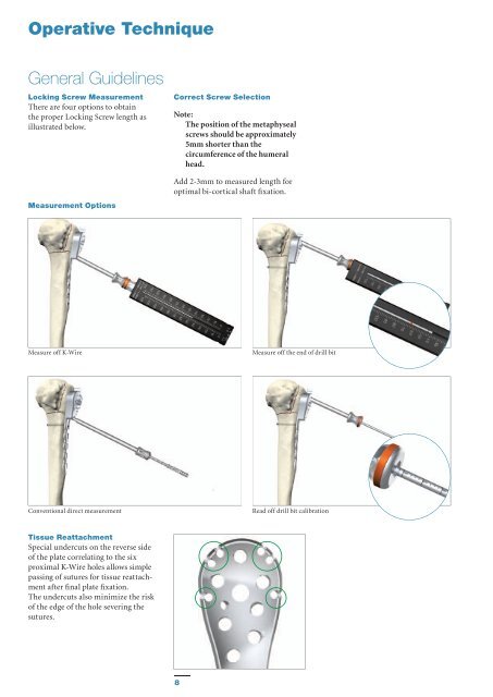
Operative Technique General Guidelines Locking Screw Measurement There are four options to obtain the proper Locking Screw length as illustrated below. Measurement Options Correct Screw Selection Note: The position of the metaphyseal screws should be approximately 5mm shorter than the circumference of the humeral head. Add 2-3mm to measured length for optimal bi-cortical shaft fixation. Measure off K-Wire Measure off the end of drill bit Conventional direct measurement Read off drill bit calibration Tissue Reattachment Special undercuts on the reverse side of the plate correlating to the six proximal K-Wire holes allows simple passing of sutures for tissue reattachment after final plate fixation. The undercuts also minimize the risk of the edge of the hole severing the sutures. 8
Operative Technique Step 1 – Pre-Operative Planning Use of the X-Ray Template (REF 981080) or Plate Trial (REF 702787) in association with fluoroscopy can help to assist in the selection of an appropriately sized implant (Fig. 1). If the Plate Trial is more than 90mm away from the bone, a magnification factor of 10-15% will occur and must be compensated for. Final intraoperative verification should be made to ensure correct implant selection. Fig. 1 Step 2 – Pre-Operative Locking Insert Application If additional Locking Screws are chosen for the plate shaft, pre-operative insertion of Locking Inserts is recommended. A 4.0mm Locking Insert (REF 370002) is attached to the Locking Insert Inserter (REF 702762) and placed into the chosen holes in the shaft portion of the plate (Fig. 2). Ensure that the Locking Insert is properly placed. The Inserter should then be removed (Fig. 2A). Note: Do not place Locking Inserts with the Drill Sleeve. Fig. 2 It is important to note that if a Temporary Plate Holder is to be used for primary distal plate fixation, then a Locking Insert should not be placed in the same hole as the Temporary Plate Holder (See Step 6). Fig. 2A 9
- Page 1 and 2: Shoulder AxSOS KnifeLight Locking P
- Page 3 and 4: Contents Page 1. Introduction 4 2.
- Page 5 and 6: Features & Benefits System • The
- Page 7: Operative Technique General Guideli
- Page 11 and 12: Operative Technique Step 3 - Aiming
- Page 13 and 14: Operative Technique Step 6 - Primar
- Page 15 and 16: Operative Technique Step 8 - Shaft
- Page 17 and 18: Additional Tips 1. Always use the t
- Page 19 and 20: Ordering Information - Implants 4.0
- Page 21 and 22: Ordering Information - Instruments
- Page 23 and 24: Additional Information - HydroSet I
<strong>Operative</strong> <strong>Technique</strong><br />
General Guidelines<br />
Locking Screw Measurement<br />
There are four options to obtain<br />
the proper Locking Screw length as<br />
illustrated below.<br />
Measurement Options<br />
Correct Screw Selection<br />
Note:<br />
The position of the metaphyseal<br />
screws should be approximately<br />
5mm shorter than the<br />
circumference of the humeral<br />
head.<br />
Add 2-3mm to measured length for<br />
optimal bi-cortical shaft fixation.<br />
Measure off K-Wire<br />
Measure off the end of drill bit<br />
Conventional direct measurement<br />
Read off drill bit calibration<br />
Tissue Reattachment<br />
Special undercuts on the reverse side<br />
of the plate correlating to the six<br />
proximal K-Wire holes allows simple<br />
passing of sutures for tissue reattachment<br />
after final plate fixation.<br />
The undercuts also minimize the risk<br />
of the edge of the hole severing the<br />
sutures.<br />
8


