AxSOS Proximal Humerus TS Operative Technique - Stryker
AxSOS Proximal Humerus TS Operative Technique - Stryker AxSOS Proximal Humerus TS Operative Technique - Stryker
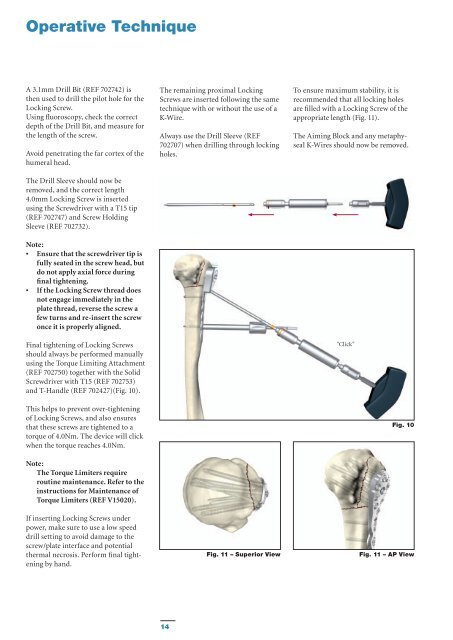
Operative Technique A 3.1mm Drill Bit (REF 702742) is then used to drill the pilot hole for the Locking Screw. Using fluoroscopy, check the correct depth of the Drill Bit, and measure for the length of the screw. Avoid penetrating the far cortex of the humeral head. The Drill Sleeve should now be removed, and the correct length 4.0mm Locking Screw is inserted using the Screwdriver with a T15 tip (REF 702747) and Screw Holding Sleeve (REF 702732). Note: • Ensure that the screwdriver tip is fully seated in the screw head, but do not apply axial force during final tightening. • If the Locking Screw thread does not engage immediately in the plate thread, reverse the screw a few turns and re-insert the screw once it is properly aligned. Final tightening of Locking Screws should always be performed manually using the Torque Limiting Attachment (REF 702750) together with the Solid Screwdriver with T15 (REF 702753) and T-Handle (REF 702427)(Fig. 10). This helps to prevent over-tightening of Locking Screws, and also ensures that these screws are tightened to a torque of 4.0Nm. The device will click when the torque reaches 4.0Nm. Note: The Torque Limiters require routine maintenance. Refer to the instructions for Maintenance of Torque Limiters (REF V15020). If inserting Locking Screws under power, make sure to use a low speed drill setting to avoid damage to the screw/plate interface and potential thermal necrosis. Perform final tightening by hand. The remaining proximal Locking Screws are inserted following the same technique with or without the use of a K-Wire. Always use the Drill Sleeve (REF 702707) when drilling through locking holes. Fig. 11 – Superior View To ensure maximum stability, it is recommended that all locking holes are filled with a Locking Screw of the appropriate length (Fig. 11). The Aiming Block and any metaphyseal K-Wires should now be removed. "Click" Fig. 10 Fig. 11 – AP View 14
Operative Technique Step 8 – Shaft Fixation The compression holes in the shaft of the plate are designed to accept either a 3.5mm Cortical Screw or a 4.0mm Locking Screw together with a Locking Insert. The threaded screw holes are designed to accept Locking Screws only. (Fig. 12). Note: If a combination of Standard and Locking Screws is used in the shaft, then the Standard Cortical Screws must be placed prior to the Locking Screws. Always lag before you lock! Locked Hole 70° Axial Angulation 14° Transverse Angulation (non-locked holes only) Option 1 – Standard Screws 3.5mm Standard cortical Screws can be placed in Neutral, Compression or Buttress positions (Fig. 13) as desired using the relevant Drill Guides and the standard technique. These screws can also act as Lag Screws. Note: This is only possible in nonthreaded holes. Buttress Compression Neutral Fig. 13 – Drill guides Fig. 13 – Drill Sleeve Handle 15
- Page 1 and 2: Shoulder AxSOS KnifeLight Locking P
- Page 3 and 4: Contents Page 1. Introduction 4 2.
- Page 5 and 6: Features & Benefits System • The
- Page 7 and 8: Operative Technique General Guideli
- Page 9 and 10: Operative Technique Step 1 - Pre-Op
- Page 11 and 12: Operative Technique Step 3 - Aiming
- Page 13: Operative Technique Step 6 - Primar
- Page 17 and 18: Additional Tips 1. Always use the t
- Page 19 and 20: Ordering Information - Implants 4.0
- Page 21 and 22: Ordering Information - Instruments
- Page 23 and 24: Additional Information - HydroSet I
<strong>Operative</strong> <strong>Technique</strong><br />
A 3.1mm Drill Bit (REF 702742) is<br />
then used to drill the pilot hole for the<br />
Locking Screw.<br />
Using fluoroscopy, check the correct<br />
depth of the Drill Bit, and measure for<br />
the length of the screw.<br />
Avoid penetrating the far cortex of the<br />
humeral head.<br />
The Drill Sleeve should now be<br />
removed, and the correct length<br />
4.0mm Locking Screw is inserted<br />
using the Screwdriver with a T15 tip<br />
(REF 702747) and Screw Holding<br />
Sleeve (REF 702732).<br />
Note:<br />
• Ensure that the screwdriver tip is<br />
fully seated in the screw head, but<br />
do not apply axial force during<br />
final tightening.<br />
• If the Locking Screw thread does<br />
not engage immediately in the<br />
plate thread, reverse the screw a<br />
few turns and re-insert the screw<br />
once it is properly aligned.<br />
Final tightening of Locking Screws<br />
should always be performed manually<br />
using the Torque Limiting Attachment<br />
(REF 702750) together with the Solid<br />
Screwdriver with T15 (REF 702753)<br />
and T-Handle (REF 702427)(Fig. 10).<br />
This helps to prevent over-tightening<br />
of Locking Screws, and also ensures<br />
that these screws are tightened to a<br />
torque of 4.0Nm. The device will click<br />
when the torque reaches 4.0Nm.<br />
Note:<br />
The Torque Limiters require<br />
routine maintenance. Refer to the<br />
instructions for Maintenance of<br />
Torque Limiters (REF V15020).<br />
If inserting Locking Screws under<br />
power, make sure to use a low speed<br />
drill setting to avoid damage to the<br />
screw/plate interface and potential<br />
thermal necrosis. Perform final tightening<br />
by hand.<br />
The remaining proximal Locking<br />
Screws are inserted following the same<br />
technique with or without the use of a<br />
K-Wire.<br />
Always use the Drill Sleeve (REF<br />
702707) when drilling through locking<br />
holes.<br />
Fig. 11 – Superior View<br />
To ensure maximum stability, it is<br />
recommended that all locking holes<br />
are filled with a Locking Screw of the<br />
appropriate length (Fig. 11).<br />
The Aiming Block and any metaphyseal<br />
K-Wires should now be removed.<br />
"Click"<br />
Fig. 10<br />
Fig. 11 – AP View<br />
14


