

Numelock II Polyaxial Locking System - Stryker
Numelock II Polyaxial Locking System - Stryker
Numelock II Polyaxial Locking System - Stryker

Create successful ePaper yourself
Turn your PDF publications into a flip-book with our unique Google optimized e-Paper software.
Indications<br />
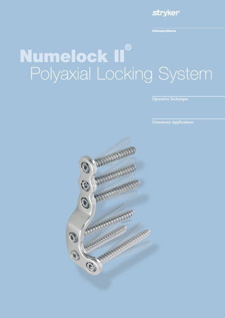
<strong>Numelock</strong> <strong>II</strong> ®<br />
<strong>Polyaxial</strong> <strong>Locking</strong> <strong>System</strong><br />
Operative Technique<br />
Osteotomy Applications
Contents<br />
Rationale 3<br />
Features and Benefits 4<br />
Indications 5<br />
Preoperative Planning 6<br />
Operative Technique<br />
• General Principles 6<br />
Ordering Information<br />
• Plates 9<br />
• Screws 10<br />
• Instruments 10<br />
• Cases and Trays 11<br />
Special acknowledgements are made to Professor Albert van Kampen, M.D., PhD<br />
and Dr. Robert Gaasbeek, M.D. of the University Medical Centre Nijmegen,<br />
the Netherlands, for sharing their technical and surgical expertise in the review of<br />
this Operative Technique.
Rationale<br />
The <strong>Numelock</strong> <strong>II</strong>® polyaxial locking mechanism provides the option of adjustability<br />
in the range of screw trajectories through a broad continuum of positions.<br />
This mechanism can be adjusted to meet the requirements of many osteotomies<br />
around the knee. This feature allows the <strong>Numelock</strong> <strong>II</strong>® plates to be correctly<br />
situated with respect to the patient’s anatomy, while each individual locking screw<br />
is accurately targeted to address the configuration of the osteotomy site and<br />
resulting bone segments.<br />
Plates<br />
The <strong>Numelock</strong> <strong>II</strong>® polyaxial locking<br />
system is designed to facilitate<br />
treatment with high tibial and distal<br />
femoral osteotomies. The shape,<br />
material properties and surface quality<br />
of the implants take into account the<br />
stringent demands of surgeons for<br />
high fatigue strength, optimized<br />
transfer of loading forces and a<br />
straightforward, standardized operative<br />
technique with broad applicability.<br />
For the purposes of safety,<br />
traceability and convenience,<br />
all plates are packaged sterile.<br />
Material<br />
Composition<br />
The implants are produced from<br />
316LVM Stainless Steel. ASTM F138<br />
and F139/ISO 5832-1 material<br />
standards provide rigid specifications<br />
that define the chemical composition,<br />
microstructural characteristics and<br />
mechanical properties of implant<br />
quality Stainless Steel. These standards<br />
ensure that 316LVM Stainless Steel,<br />
even if provided by different suppliers,<br />
is consistent and compatible.<br />
The material used for all <strong>Numelock</strong> <strong>II</strong>®<br />
plates and screws meets these<br />
standards.<br />
<strong>Locking</strong> Screws<br />
The <strong>Numelock</strong> <strong>II</strong>® locking screws used<br />
with the <strong>Numelock</strong> <strong>II</strong>® Osteotomy<br />
Plates have a thread diameter of<br />
6.5mm. All <strong>Numelock</strong> <strong>II</strong>® locking<br />
screws are packaged sterile and are<br />
provided in lengths from 27mm to<br />
85mm (27mm – 45mm in 3mm<br />
increments and 50mm – 85mm in<br />
5mm increments). The locking screws<br />
have a unique core design and thread<br />
pattern in the head and tip areas.<br />
As the screw is threaded into the<br />
locking mechanism (see below),<br />
its conical head part engages with<br />
the corresponding threads in the ring,<br />
which then expands into the plate,<br />
securely locking the position of the<br />
screw at the chosen angle and<br />
direction.<br />
<strong>Polyaxial</strong> <strong>Locking</strong><br />
Mechanism<br />
Every hole of each osteotomy plate<br />
(except Ref. No. STP2Y76S) is<br />
equipped with an integral polyaxial<br />
locking mechanism which will accept<br />
6.5mm diameter <strong>Numelock</strong> <strong>II</strong>®<br />
locking screws.<br />
The screw securely locks into the plate<br />
at the desired angle and direction.<br />
Prior to final locking of the<br />
<strong>Numelock</strong> <strong>II</strong> ® screw within the<br />
mechanism, the ring is designed to<br />
rotate freely. This attribute can be used<br />
to pull a bone segment into alignment<br />
(see Operative Technique – General<br />
Principles, Step Six, for additional<br />
information on this feature).<br />
Instrumentation<br />
The <strong>Numelock</strong> <strong>II</strong>® instruments are<br />
designed for accuracy and ease of<br />
use and precisely engage with all<br />
<strong>Numelock</strong> <strong>II</strong>® implant components.<br />
The storage trays conveniently house<br />
the instrument set.<br />
This mechanism permits the screws to<br />
be targeted through a cone of up to 30°<br />
in all directions. This capability allows<br />
the surgeon to aim each screw at an<br />
optimal trajectory within the 30° cone.<br />
3
Features and Benefits<br />
Features<br />
Axially stable, locking fixation<br />
<strong>Polyaxial</strong> locking mechanism<br />
30º range of screw insertion angles<br />
All plates and screws packaged sterile<br />
Screws with unique thread and conical<br />
core design<br />
Ring Driver permits screw<br />
and bone segment adjustments<br />
<strong>Numelock</strong> screws accept<br />
standard hex drivers<br />
Rounded plate ends<br />
Drill guide constrains screw<br />
insertion angle<br />
<strong>Numelock</strong> <strong>II</strong> ® Screw Depth Gauge<br />
gives direct value<br />
Benefits<br />
• High stability; protection against<br />
primary and secondary losses of<br />
reduction; limited plate contact with<br />
periostium; reliable purchase in<br />
normal and osteoporotic bone.<br />
• Screws positioned according to<br />
osteotomy surface or to avoid another<br />
implant; plate positioned to meet<br />
needs of patient anatomy.<br />
• Adjustability in range of screw<br />
trajectories for optimized fixation.<br />
• Safety, traceability, convenience.<br />
• Low insertion torque and secure<br />
locking; reduced possibility of<br />
cross-threading and cold welding.<br />
• Distance of bone to plate can be<br />
accurately adjusted; bone segments<br />
may be pulled towards plate.<br />
• Screws can be removed with standard<br />
hex drivers at end of treatment, in case<br />
of plate extraction.<br />
• Reduced potential for soft tissue<br />
irritation.<br />
• Limits screw head protrusion<br />
for reduced soft tissue irritation;<br />
insures optimal surface contact of ring<br />
to plate.<br />
• No compensation required<br />
for <strong>Numelock</strong> <strong>II</strong> ® locking screws.<br />
4
Indications<br />
The <strong>Numelock</strong> <strong>II</strong> ® Osteotomy <strong>System</strong>’s<br />
implants and instruments facilitate<br />
performance of high tibial and distal<br />
femoral osteotomies using the opening<br />
and closing wedge techniques.<br />
Specific indications include the<br />
following:<br />
• Unicompartmental osteoarthritis.<br />
• Congenital and post traumatic<br />
varus or valgus deformities and<br />
malalignments.<br />
• Posterolateral knee instability.<br />
The physician’s education, training<br />
and professional judgment must be<br />
relied upon to choose the most<br />
appropriate device and treatment<br />
option. Conditions presenting an<br />
increased risk of failure include:<br />
• Presence of inflammatory arthritis.<br />
• Severe joint instability cannot be<br />
treated through osteotomy alone;<br />
additional ligament reconstruction<br />
is required.<br />
• Any active or suspected latent<br />
infection or marked local inflammation<br />
in or about the affected area.<br />
• Compromised vascularity that would<br />
inhibit adequate blood supply to the<br />
osteotomy or the operative site.<br />
• Bone stock compromised by disease,<br />
infection or prior implantation that<br />
cannot provide adequate support<br />
and/or fixation of the devices.<br />
• Material sensitivity documented or<br />
suspected.<br />
• Obesity. An overweight or obese<br />
patient can produce loads on the<br />
implant which can lead to failure of<br />
the fixation of the device or to failure<br />
of the device itself.<br />
• Patients having inadequate tissue<br />
coverage over the operative site.<br />
• Implant utilization that would<br />
interfere with anatomical structures<br />
or physiological performance.<br />
• Any mental or neuromuscular<br />
disorder which could create an<br />
unacceptable risk of fixation<br />
failure or complications in<br />
postoperative care.<br />
• Other medical or surgical<br />
conditions which would preclude<br />
the potential benefit of surgery.<br />
5
Operative Technique<br />
Preoperative Planning<br />
The surgeon must first determine and<br />
clearly characterize the nature and<br />
extent of the deformity being<br />
corrected. For this purpose, full-length,<br />
standing (long axial alignment) AP<br />
radiographs need to be obtained.<br />
The x-rays must include the hip,<br />
knee and talus, standing in extension.<br />
The x-ray beam should be centered<br />
on the knee in question. It is also<br />
recommended that a standing lateral<br />
view and an anteroposterior view of<br />
the knee bent at 45° be obtained.<br />
These x-rays are then used to classify<br />
the orientation and magnitude of the<br />
deformity to be corrected using<br />
standard methods as described in the<br />
literature. The mechanical axis of the<br />
patient is defined by a line drawn from<br />
the center of the femoral head to the<br />
center of the tibial-talar joint.<br />
The radiographic evaluation is also<br />
used to determine the site of the<br />
osteotomy, the method of correction<br />
(opening or closing wedge)<br />
and positioning of the plate.<br />
General Principles<br />
It is recommended that any osteotomy<br />
be performed on a radiolucent table<br />
to allow visualization of the hip, knee<br />
and ankle. During the procedure,<br />
it is necessary for the surgeon to have<br />
a clear view of the entire extremity<br />
from the iliac crest to the talus.<br />
A choice of incision consistent with the<br />
anatomical region in question is made<br />
by the surgeon, based on personal<br />
experience and patient considerations.<br />
When treating a tibial deformity<br />
with a closing wedge osteotomy,<br />
the tibiofibular joint will prevent<br />
correction unless the fibula or the<br />
tibiofibular ligaments are cut.<br />
One option is to perform an oblique<br />
fibular osteotomy through a small<br />
incision in the proximal middle third<br />
of the fibula.<br />
Step One – Closing Wedge<br />
Osteotomy and Opening<br />
Osteotomy Wedge Sizing<br />
• The Cutting Guide (Ref. No. GCTP)<br />
in conjunction with fluoroscopic<br />
control permits accurate incisions to<br />
be made for closing wedge osteotomies.<br />
The first cut is made parallel to the<br />
joint line without the Cutting Guide.<br />
Insertion of two K-wires may be<br />
helpful in establishing the plane<br />
and location of the first cut.<br />
• After completion of the first cut, the<br />
Cutting Guide’s flange (see Fig. 1) is<br />
placed into this incision. Adjustment<br />
of the graduated scale allows for<br />
precise angulation of the second<br />
cutting line. For right leg osteotomies,<br />
use the side of the scale indicated by<br />
the letter “D.” For left leg osteotomies<br />
use the side of the scale marked “G.”<br />
Note: The “D” represents “Droite”<br />
(Right) and the “G” represents<br />
“Gauche” (Left) in French.<br />
• When performing an opening wedge<br />
osteotomy, a bone spreader can be<br />
used to pry open the osteotomy site<br />
and keep it from collapsing, while<br />
a bone clamp is used to secure the<br />
opposite aspect so that it does not<br />
displace. It is often useful to keep<br />
a small corner of the far cortex intact<br />
to help maintain stability.<br />
• Use the Trial Wedges (Ref. No.<br />
10CALES) to ensure that the correct<br />
angular position is maintained and<br />
also to help open the osteotomy gap.<br />
If bone filler is used, these Trial<br />
Wedges can also help in determining<br />
the correct size and shape of the<br />
actual wedge to be implanted in the<br />
gap. The Trial Wedges are conveniently<br />
held and manipulated into position<br />
with the Holder (Ref. No. PRCAL).<br />
The Trial Wedge is removed after<br />
stabilization of the osteotomy site.<br />
Flange<br />
Graduated Scale<br />
Figure 1<br />
6
Operative Technique<br />
Step Two – Plate Contouring<br />
• The selected plate may require some<br />
contouring. When shaping the<br />
implant, the <strong>Numelock</strong> <strong>II</strong>® polyaxial<br />
mechanisms must be protected by<br />
grasping the plate with two Bending<br />
Forceps (Ref. No. PFTP3I), ensuring<br />
that the single rounded knob of each<br />
of the Bending Forceps is securely<br />
seated in the holes adjacent to the<br />
area of the plate that is being bent<br />
(See Figure 2). If twisting of the plate<br />
is required, a single Forceps, in<br />
combination with a Plate Bending<br />
Iron (Ref. No. TRTP3), may be used.<br />
Step Three – Pre-drilling for<br />
<strong>Locking</strong> Screw Placement<br />
• Once the required shape has been<br />
fashioned, the plate should be<br />
positioned on the bone for optimal<br />
stability and ultimate fixation.<br />
• Make certain that the locking<br />
mechanisms are correctly oriented:<br />
The slotted sides of the rings must all<br />
be turned to face upwards (away from<br />
the underside of the plate).<br />
• The <strong>Numelock</strong> <strong>II</strong>® Drill Guide<br />
(Ref. No. GM35 for use with a 3.5mm<br />
drill bit or Ref. No. GM45 for use<br />
with a 4.5mm drill bit) is threaded<br />
into the locking mechanism of one of<br />
the holes (See Figure 3). The 3.5mm<br />
drill bit is recommended for normal<br />
bone. The Drill Guide is then<br />
positioned at the required angle and<br />
the appropriate diameter drill bit is<br />
used to create a pilot hole for screw<br />
insertion. The Drill Guide constrains<br />
the drilling angle to within 30°,<br />
ensuring optimal screw head profile<br />
to minimize possible soft tissue<br />
irritation.<br />
• If hard cortical bone is encountered,<br />
use the tip of the Cutting Screwdriver<br />
(Ref. No. TASH7) to incise the near<br />
cortex. Additionally, a 4.5mm drill bit<br />
may be used to overdrill the near<br />
cortex in case of hard bone. The Tap<br />
(Ref. No. TVSH7) may be used to<br />
further prepare a pilot hole that was<br />
drilled using the 4.5mm drill bit.<br />
Step Four – Depth Measurement<br />
• Using the Depth Gauge (Ref. No. JA65),<br />
measure the depth of the pilot holes<br />
directly through the plate<br />
(See Figure 4).<br />
Figure 2<br />
Note: Special care must be taken to<br />
prevent damage to the locking<br />
mechanism. To protect the<br />
mechanism from damage, apply<br />
bending only between the locking<br />
holes. Do not back bend the plate.<br />
The Bending Forceps<br />
(Ref. No. PFTP3I) and Plate<br />
Bending Irons (Ref. No. TRTP3)<br />
must not be used to bend the<br />
femoral plates as they are already<br />
pre-contoured in an optimal<br />
manner.<br />
Figure 3<br />
• It is important to preplan the angles<br />
of inclination for each of the locking<br />
screws to optimize the fixation<br />
of both osteotomy segments.<br />
Extreme caution needs to be exercised<br />
to avoid collision of any screws inside<br />
the bone and to avoid penetration<br />
of the joint surfaces.When feasible,<br />
to avoid such intersection of the<br />
<strong>Numelock</strong> <strong>II</strong>® screws within the bone,<br />
it is desirable to place them at<br />
divergent angles to each other.<br />
Figure 4<br />
The Depth Gauge provides the actual<br />
length of the screw required.<br />
Note that the “Y” Shaped Plate with<br />
Compression Hole (Ref. No. STP2Y76S)<br />
uses standard 4.5mm SPS cortical<br />
screws in the shaft. Use the Depth<br />
Gauge from the Basic Fragment SPS<br />
set (Ref. No. 702878) for correct<br />
measurement of the diaphyseal screws<br />
in this plate.<br />
7
Operative Technique<br />
Step Five – <strong>Locking</strong> Screw<br />
Placement<br />
• Using the Cutting Screwdriver<br />
(Ref. No. TASH7), insert the<br />
<strong>Numelock</strong>® locking screw as far as<br />
possible without locking the ring<br />
mechanism. Prevent rotation of the<br />
ring mechanism by engaging the<br />
Holding Spanner’s (Ref. No. CESH7)<br />
teeth with the corresponding slots in<br />
the ring (See Figure 5).<br />
Step Six – Final Adjustments/<br />
Repositioning/Transport<br />
• To adjust the position of the bone<br />
with respect to the plate or to pull<br />
a bone segment closer to the plate,<br />
use the Ring Driver (Ref. No. TVESH7).<br />
By turning the ring clockwise with<br />
the Ring Driver, the bone is moved<br />
closer to the plate as required.<br />
Note: If using this feature to realign<br />
two bone segments, the<br />
orientation of screw placement<br />
must be parallel to the plane of<br />
the osteotomy line associated<br />
with these two segments.<br />
Step Seven – Final <strong>Locking</strong><br />
• When all desired adjustments are<br />
complete, lock each <strong>Numelock</strong> <strong>II</strong>®<br />
screw with the Screwdriver while<br />
holding the ring steady with the<br />
Holding Spanner. Firm tightening<br />
of the screws ensures stability.<br />
After locking, it is no longer possible<br />
to rotate the ring without damaging<br />
the locking mechanism.<br />
Figure 5<br />
Repeat Steps Three through Five<br />
for all screw positions. If transport<br />
or repositioning of a bone segment<br />
is required, see Step Six.<br />
Note: To guarantee maximum stability,<br />
fill all <strong>Numelock</strong> <strong>II</strong>® holes with<br />
a locking screw of appropriate<br />
length.<br />
Postoperative Care<br />
The physician’s education, training and<br />
professional judgment must be relied<br />
upon to establish the most appropriate<br />
postoperative care regimen for each<br />
individual patient. The following<br />
recommendations may be considered<br />
at the surgeon’s discretion:<br />
• Some patients may need to spend<br />
several days in the hospital after an<br />
osteotomy procedure. Deep muscle<br />
compartment drains may need to be<br />
considered postoperatively as well as a<br />
suitable pain management protocol.<br />
• If warranted, continuous passive<br />
motion may begin during the second<br />
postoperative day to help restore<br />
mobility. When appropriate,<br />
toe-touch weight-bearing with<br />
crutches may follow.<br />
• Follow-up radiographs are<br />
recommended at six weeks after<br />
surgery. Weight-bearing may be<br />
gradually increased at the surgeon’s<br />
discretion or when there is<br />
radiographic evidence of union.<br />
Full weight-bearing may begin when<br />
there is full consolidation of the<br />
osteotomy site, typically at around<br />
eight to ten weeks for men and ten<br />
to twelve weeks for women.<br />
8
Ordering Information – Osteotomy Plates<br />
Stainless Steel, Packaged Sterile<br />
MEDIAL DISTAL FEMORAL, CLOSING<br />
<strong>Locking</strong> Screws Diameter 6.5mm<br />
MEDIAL PROXIMAL TIBIAL “Y” SHAPED, OPENING<br />
<strong>Locking</strong> Screws Diameter 6.5mm<br />
StSt Length Side <strong>Locking</strong> Shaft<br />
REF mm Holes Holes<br />
SFBIPOSTDS 91 Right 6 3<br />
SFBIPOSTGS 91 Left 6 3<br />
StSt Length Side <strong>Locking</strong> Shaft<br />
REF mm Holes Holes<br />
STP2Y70S 69 Sym 4 2<br />
STP2Y94S 94 Sym 4 2<br />
STP2Y114S 114 Sym 4 2<br />
LATERAL PROXIMAL TIBIAL “L” SHAPED, CLOSING<br />
<strong>Locking</strong> Screws Diameter 6.5mm<br />
MEDIAL PROXIMAL TIBIAL “L” SHAPED, OPENING<br />
<strong>Locking</strong> Screws Diameter 6.5mm<br />
StSt Length Side <strong>Locking</strong> Shaft<br />
REF mm Holes Holes<br />
STP2L61FDS 59 Right 4 2<br />
STP2L61FGS 59 Left 4 2<br />
StSt Length Side <strong>Locking</strong> Shaft<br />
REF mm Holes Holes<br />
STP2L64ODS 63 Right 4 2<br />
STP2L64OGS 63 Left 4 2<br />
59mm<br />
StSt Length Side <strong>Locking</strong> Shaft<br />
REF mm Holes Holes<br />
STP2L64FDS 63 Right 4 2<br />
STP2L64FGS 63 Left 4 2<br />
MEDIAL PROXIMAL TIBIAL “Y” SHAPED,<br />
OPENING WITH COMPRESSION HOLE<br />
<strong>Locking</strong> Screws Diameter 6.5mm<br />
Standard Screws Diameter 4.5mm (for shaft holes only)<br />
StSt Length Side <strong>Locking</strong> Shaft<br />
REF mm Holes Holes<br />
STP2Y76S 77 Sym 2 3<br />
63mm<br />
9
Ordering Information – Screws / Instruments<br />
6.5mm diameter <strong>Locking</strong> Screws,<br />
Stainless Steel, Packaged Sterile<br />
StSt<br />
Length<br />
REF<br />
mm<br />
S7SH27S 27<br />
S7SH30S 30<br />
S7SH33S 33<br />
S7SH36S 36<br />
S7SH39S 39<br />
S7SH42S 42<br />
S7SH45S 45<br />
S7SH50S 50<br />
S7SH55S 55<br />
S7SH60S 60<br />
S7SH65S 65<br />
S7SH70S 70<br />
S7SH75S 75<br />
S7SH80S 80<br />
S7SH85S 85<br />
6.5mm Instrumentation<br />
REF<br />
GCTP<br />
PRCAL<br />
10CALES<br />
PFTP3I<br />
TRTP3<br />
GM35<br />
MCA35195<br />
GM45<br />
MCA45195<br />
TVSH7<br />
JA65<br />
CESH7<br />
Description<br />
Cutting Guide<br />
Holder for Trial Wedges<br />
Set of 10 Trial Wedges<br />
Bending Forceps (Two Required)<br />
Plate Bending Iron<br />
Drill Guide for 3.5mm Drill Bit<br />
3.5mm Drill Bit<br />
Drill Guide for 4.5mm Drill Bit<br />
4.5mm Drill Bit<br />
Tap<br />
Depth Gauge<br />
Holding Spanner<br />
TASH7<br />
TVESH7<br />
Cutting Screwdriver<br />
Ring Driver<br />
10
Ordering Information – Cases and Trays<br />
REF<br />
Description<br />
Metal Case configuration<br />
CSA2F240 Storage Case, Instruments<br />
11
Trauma, Extremities & Deformities<br />
Trauma, Extremities & Deformities<br />
Biologics<br />
Biologics<br />
Surgical Products<br />
Surgical Products<br />
Neuro & ENT<br />
Neuro & ENT<br />
<strong>Stryker</strong> Trauma AG<br />
Bohnackerweg 1<br />
CH-2545 Selzach<br />
Switzerland<br />
www.osteosynthesis.stryker.com<br />
The information presented in this brochure is intended to demonstrate a <strong>Stryker</strong> product. Always refer to the package<br />
insert, product label and/or user instructions before using any <strong>Stryker</strong> product. Surgeons must always rely on their own<br />
clinical judgment when deciding which products and techniques to use with their patients. Products may not be available<br />
in all markets. Product availability is subject to the regulatory or medical practices that govern individual markets. Please<br />
contact your <strong>Stryker</strong> representative if you have questions about the availability of <strong>Stryker</strong> products in your area.<br />
<strong>Stryker</strong> Corporation or its subsidiary owns the registered trademark: <strong>Stryker</strong><br />
<strong>Stryker</strong> Corporation or its subsidiary owns, uses or has applied for the following trademarks: <strong>Numelock</strong> <strong>II</strong><br />
Literature Number: 982196<br />
LOT A4106<br />
Copyright © 2006 <strong>Stryker</strong><br />
Printed in Switzerland


