

AxSOS Extremity Plating System Operative Technique - Stryker
AxSOS Extremity Plating System Operative Technique - Stryker
AxSOS Extremity Plating System Operative Technique - Stryker

Create successful ePaper yourself
Turn your PDF publications into a flip-book with our unique Google optimized e-Paper software.
Shoulder<br />
Elbow<br />
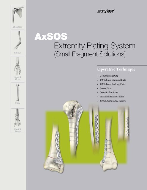
<strong>AxSOS</strong><br />
<strong>Extremity</strong> <strong>Plating</strong> <strong>System</strong><br />
(Small Fragment Solutions)<br />
<strong>Operative</strong> <strong>Technique</strong><br />
Hand &<br />
Wrist<br />
Tibia<br />
• Compression Plate<br />
• 1/3 Tubular Standard Plate<br />
• 1/3 Tubular Locking Plate<br />
• Recon Plate<br />
• Distal Radius Plate<br />
• Proximal Humerus Plate<br />
• 4.0mm Cannulated Screws<br />
Foot &<br />
Ankle
<strong>AxSOS</strong> <strong>Extremity</strong> <strong>Plating</strong> <strong>System</strong><br />
This publication sets forth detailed<br />
recommended procedures for using<br />
<strong>Stryker</strong> Osteosynthesis devices and<br />
instruments.<br />
It offers guidance that you should<br />
heed, but, as with any such technical<br />
guide, each surgeon must considerthe<br />
particular needs of each patient and<br />
make appropriate adjustments when and<br />
as required.<br />
A workshop training is recommended<br />
prior to first surgery.<br />
All non-sterile devices must be<br />
cleaned and sterilized before use.<br />
Follow the instructions provided in<br />
our reprocessing guide (L24002000).<br />
Multi-component instruments must be<br />
disassembled for cleaning. Please refer to<br />
the corresponding assembly/disassembly<br />
instructions.<br />
See package insert (V15011 and V15013)<br />
for a complete list of potential adverse<br />
effects, contraindications, warnings and<br />
precautions. The surgeon must discuss<br />
all relevant risks, including the finite<br />
lifetime of the device, with the patient,<br />
when necessary.<br />
Warning:<br />
Fixation Screws:<br />
<strong>Stryker</strong> Osteosynthesis bone screws<br />
are not approved or intended for screw<br />
attachment or fixation to the posterior<br />
elements (pedicles) of the cervical,<br />
thoracic or lumbar spine.<br />
2
Contents<br />
Page<br />
1. Introduction 4<br />
2. Features & Benefits 5<br />
3. Indications & Contraindications 10<br />
4. <strong>Operative</strong> <strong>Technique</strong> 11<br />
Ordering Information – Plates 17<br />
Ordering Information – Screws 19<br />
Ordering Information – <strong>AxSOS</strong> Instruments 20<br />
3
Introduction<br />
The <strong>AxSOS</strong> locking plate system<br />
design is based on clinical input from<br />
an international panel of experienced<br />
surgeons, data from literature, and both<br />
practical and biomechanical testing.<br />
The anatomical shape, the fixed screw<br />
trajectory, and high surface quality<br />
take into account the current demands<br />
of clinical physicians for appropriate<br />
fixation, high fatigue strength,<br />
and minimal soft tissue damage.<br />
3mm Distal Radius Plate<br />
4mm Proximal Humeral Plate<br />
3mm Locking Insert<br />
4mm Recon Plate<br />
4mm Locking Insert<br />
3mm<br />
1/3 Tubular<br />
Locking Plate<br />
3.5mm<br />
1/3 Tubular<br />
Standard Plate<br />
4mm<br />
Compression<br />
Plate<br />
4
Features & Benefits<br />
Tray Layout<br />
Cases and Trays<br />
The <strong>AxSOS</strong> <strong>Extremity</strong> <strong>Plating</strong> <strong>System</strong><br />
consists of four individual trays<br />
containing a wide assortment of plates,<br />
screws, and reduction instruments.<br />
The tray inserts are color coded and<br />
organized to offer modularity for storage<br />
and sterilization.<br />
Level 1<br />
Contains commonly used compression,<br />
reconstruction, 1/3 tubular, specialized<br />
periarticular locking plates for the distal<br />
radius and proximal humerus, as well as<br />
Asnis III 4.0 Cannulated Screw instruments.<br />
Level 2<br />
Contains instrumentation such as<br />
aiming blocks, drill guides, drill bits,<br />
screwdrivers and measuring gauges for<br />
SPS and 4.0 Locking Plate <strong>System</strong>s.<br />
Level 3<br />
Contains additional instrumentation<br />
such as aiming blocks, drill guides, drill<br />
bits, screwdrivers, measuring gauges,<br />
as well as bending and reduction<br />
instruments for SPS and 3.0 Locking<br />
Plate <strong>System</strong>s.<br />
Screw Rack contains 2.7mm & 3.5mm<br />
cortical screws, 4.0mm fully threaded<br />
& partially threaded cancellous screws,<br />
3.0mm & 4.0mm locking screws and<br />
4.0mm Asnis cannulated screws.<br />
Level 4<br />
Contains additional reduction<br />
instruments and a compartment for<br />
additional implants and instruments<br />
allowing for further set customization.<br />
<strong>System</strong> Color Scheme<br />
Green: 4.0mm Asnis<br />
Tan: SPS Non-Locking<br />
Orange: 4.0mm <strong>AxSOS</strong> Locking<br />
White: 3.0mm <strong>AxSOS</strong> Locking<br />
5
Features & Benefits<br />
<strong>AxSOS</strong> Periarticular Plates<br />
Proximal Humerus (4mm)<br />
K-Wire / Suture Holes<br />
• Primary/temporary<br />
plate and fracture fixation<br />
• Suturing<br />
Distal Volar Radius (3mm)<br />
Monoaxial Holes<br />
• Allow axially stable screw placement,<br />
bringing stability to construct<br />
Unthreaded Freedom Holes<br />
• Freehand placement of screws<br />
• Lag screw possibility<br />
Anatomically Contoured<br />
• Little or no bending required.<br />
• Designed to provide soft tissue<br />
coverage<br />
Shaft Holes - Standard or Locking<br />
• Compression, neutral or buttress<br />
fixation<br />
• Accept standard SPS screws<br />
• Accept Locking Insert for axially<br />
stable screws<br />
• Pre-drilled Locking Holes allow<br />
axially stable screw placement<br />
‘Waisted’ Plate Shape<br />
• Uniform load transfer.<br />
Rounded & Tapered Plate End<br />
• Designed to help facilitate sliding<br />
of plates sub-muscularly<br />
Aiming Block<br />
• Designed to help provide accurate<br />
placement of the Drill Sleeve<br />
• Provides attachment point for Plate<br />
Insertion Handle<br />
Innovative Locking Screw Design<br />
• Screw is guided into plate.<br />
6
Features & Benefits<br />
<strong>AxSOS</strong> 4.0 Compression Plates<br />
Compression and/or Locking Plate<br />
Option<br />
• The Locking Inserts and Locking<br />
Screws convert a standard compression<br />
hole to a locking hole.<br />
‘Waisted’ Plate Shape<br />
• Uniform load transfer.<br />
Equal Hole Spacing<br />
• Greater operative flexibility for screw<br />
and plate placement.<br />
Standard or Locking Holes<br />
• Compression, neutral or buttress<br />
fixation<br />
• Accept standard 3.5/4.0mm<br />
SPS screws<br />
• Accept Locking Insert for <strong>AxSOS</strong><br />
4.0mm locking screws<br />
K-Wire and Reduction Holes<br />
• Enhanced primary/temporary plate<br />
and fracture fixation.<br />
Innovative Locking Screw Design<br />
• Screw is guided into plate<br />
Low Screw Head Profile<br />
• Designed to provide adequate<br />
soft tissue coverage.<br />
Rounded and Tapered Plate Ends<br />
• Designed to help facilitate sliding<br />
of plates sub-muscularly<br />
7
Features & Benefits<br />
Reconstruction & 1/3 Tubular Plates<br />
4mm Reconstruction Plate<br />
Annealed Stainless Steel<br />
• The reconstruction plates are<br />
made of annealed stainless steel,<br />
which facilitates three-dimensional<br />
bending of the plate for an anatomical<br />
fit.<br />
Threaded Locking Holes<br />
• Plate holes accept a self tapping locking<br />
screw to help provide adequate stability<br />
to the plate/screw construct.<br />
K-Wire and Reduction Holes<br />
• Enhanced primary/temporary plate<br />
and fracture fixation.<br />
1/3 Tubular<br />
Locking Plate<br />
1/3 Tubular<br />
Standard Plate<br />
Threaded Locking Holes<br />
• Plate holes accept a self tapping<br />
locking screw to help provide adequate<br />
stability to the plate/screw construct.<br />
K-Wire and Reduction Holes<br />
• Enhanced primary/temporary plate<br />
and fracture fixation.<br />
8
Features & Benefits<br />
Asnis III 4.0mm<br />
The Asnis III Cannulated Screw <strong>System</strong><br />
is designed to assist surgical outcomes<br />
while simplifying procedures.<br />
The system incorporates several unique<br />
features intended to enhance screw<br />
placement, insertion and removal as<br />
follows:<br />
Low Profile Screw Head<br />
Stainless Steel (316LVM)<br />
• Compatibility with current steel<br />
systems.<br />
• Clinical Historical Use<br />
Packaging<br />
• Implants individually sterile packaged.<br />
Shaft and Core Diameter Equal<br />
Reverse Cutting Flute<br />
• To facilitate removal.<br />
Thread Choice<br />
• Implants available with both partial<br />
and fully threaded options.<br />
Self-Drilling/Tapping Design<br />
Large Diameter Guide Wires<br />
• To provide more precise screw<br />
placement.<br />
9
Indications & Contraindications<br />
Indications<br />
Fractures of the metaphysis and/or the<br />
diaphysis of the following:<br />
· One Third Tubular Plates: Fibula,<br />
metetarsals, metacarpals.<br />
· Compression Plate: Radius, ulna, distal<br />
tibia, fibula, distal humerus.<br />
· Reconstruction Plates: Humerus, pelvis.<br />
· The <strong>AxSOS</strong> Plus Locking Plate<br />
<strong>System</strong> is intended for use in long bone<br />
fracture fixation, including but not<br />
limited to fractures of the humerus and<br />
distal radius.<br />
Asnis III Cannulated Screws are<br />
indicated for fracture fixation of small<br />
and long bones and of the pelvis.<br />
Precautions<br />
<strong>Stryker</strong> Osteosynthesis systems have not<br />
been evaluated for safety and use in MR<br />
environment and have not been tested<br />
for heating or migration in the MR<br />
environment, unless specified otherwise<br />
in the product labeling.<br />
Contraindications<br />
The physician’s education, training<br />
and professional judgement must<br />
be relied upon to choose the most<br />
appropriate device and treatment.<br />
Conditions<br />
presenting an increased risk of failure<br />
include:<br />
• Any active or suspected latent infection<br />
or marked local inflammation in or<br />
about the affected area.<br />
• Compromised vascularity that would<br />
inhibit adequate blood supply to the<br />
fracture or the operative site.<br />
• Bone stock compromised by disease,<br />
infection or prior implantation that<br />
can not provide adequate support<br />
and/or fixation of the devices.<br />
• Material sensitivity, documented<br />
or suspected.<br />
• Obesity. An overweight or obese<br />
patient can produce loads on the<br />
implant that can lead to failure of the<br />
fixation of the device or to failure<br />
of the device itself.<br />
• Patients having inadequate tissue<br />
coverage over the operative site.<br />
• Implant utilization that would<br />
interfere with anatomical structures<br />
or physiological performance.<br />
• Any mental or neuromuscular<br />
disorder which would create an<br />
unacceptable risk of fixation failure<br />
or complications in postoperative care.<br />
• Other medical or surgical conditions<br />
which would preclude the potential<br />
benefit of surgery.<br />
Warning<br />
This publication sets forth detailed<br />
recommended procedures for using<br />
<strong>Stryker</strong> Osteosynthesis devices and<br />
instruments.<br />
It offers guidance that you should<br />
heed, but, as with any such technical<br />
guide, each surgeon must consider the<br />
particular needs of each patient and<br />
make appropriate adjustments when<br />
and as required. A workshop training is<br />
recommended prior to first surgery.<br />
All non-sterile devices must be cleaned<br />
and sterilized before use. Follow<br />
the instructions provided in our<br />
reprocessing guide (L24002000).<br />
Multi-component instruments must<br />
be disassembled for cleaning. Please<br />
refer to the corresponding assembly/<br />
disassembly instructions.<br />
See package insert (V15011 and V15013)<br />
for a complete list of potential adverse<br />
effects, contraindications, warnings and<br />
precautions. The surgeon must discuss<br />
all relevant risks, including the finite<br />
lifetime of the device, with the patient,<br />
when necessary.<br />
Warning:<br />
Fixation Screws: <strong>Stryker</strong><br />
Osteosynthesis bone screws are<br />
not approved or intended for screw<br />
attachment or fixation to the posterior<br />
elements (pedicles) of the cervical,<br />
thoracic or lumbar spine.<br />
Caution<br />
Federal law (U.S.A.) restricts this<br />
device to sale by or on the order of<br />
a licensed physician.<br />
10
<strong>Operative</strong> <strong>Technique</strong><br />
<strong>AxSOS</strong> Compression Plates<br />
The <strong>AxSOS</strong> Small and Basic Fragment<br />
<strong>System</strong>s function in the same general<br />
operative manner as the SPS Small<br />
and Basic Fragment <strong>System</strong>s in the<br />
conventional non-locking mode.<br />
The procedure below illustrates how<br />
to convert an <strong>AxSOS</strong> Plate Hole from<br />
a compression mode to an un-locked<br />
mode.<br />
<strong>AxSOS</strong> Compression Plates<br />
or SPS Compression Plates<br />
The <strong>AxSOS</strong> Compression Plate<br />
should not be confused with the SPS<br />
Compression Plate. The standard SPS<br />
Plate cannot be locked, and therefore<br />
should not be used with Locking Screws,<br />
Locking Inserts, or Cable Plugs.<br />
The <strong>AxSOS</strong> Compression Plate can<br />
be used both in compression and/or<br />
locking mode.<br />
Each system has its own Reference<br />
Numbers, and there are 2 visible<br />
differences between the plates.<br />
The <strong>AxSOS</strong> plate has a “matte” finish,<br />
while the SPS plate has a “polish” finish.<br />
Second, the plates have different tapers<br />
at the plate ends as illustrated in (Fig. 1).<br />
SPS Compression Plate<br />
<strong>AxSOS</strong> Compression Plate<br />
Fig. 1<br />
Bending<br />
If the plate is used in a fully locked mode,<br />
plate bending is not recommended due<br />
to possible hole deformity and inability<br />
of Locking Insert placement.<br />
<strong>AxSOS</strong><br />
Compression Plates Cortical Screws Locking Screws<br />
Small Fragment 3.5mm 4.0mm<br />
If the plate is used in a hybrid mode<br />
(compression with appropriate cortical<br />
screws and locking screws), the plate<br />
should only be bent at the level of the<br />
fracture line between the compression<br />
holes.<br />
Hybrid Mode Screw Insertion<br />
When using the plate in a hybrid mode,<br />
it is essential to insert the Cortical<br />
Screws for axial compression before<br />
inserting any Locking Screws.<br />
11
<strong>Operative</strong> <strong>Technique</strong><br />
<strong>AxSOS</strong> Compression Plates<br />
Option 1: Locking Insert<br />
Application<br />
If an <strong>AxSOS</strong> Plate is used in a locking<br />
mode, pre-operative insertion of<br />
Locking Inserts is recommended.<br />
A Locking Insert (4.0mm - REF 370002)<br />
is attached to the Locking Insert Inserter<br />
(4.0mm - REF 702762) and placed into<br />
the chosen hole(s) of the plate (Fig. 2).<br />
Ensure that the Locking Insert is<br />
properly placed. The Inserter should<br />
then be removed (Fig. 3). Do not place<br />
Locking Inserts with the Drill Sleeve.<br />
Fig. 2 Fig. 3<br />
Locking Screw Insertion<br />
Locking Screws can be placed in plate<br />
holes provided there is a pre-placed<br />
locking insert. The appropriate Drill Sleeve<br />
is threaded into the Locking Insert to<br />
ensure initial fixation of the Locking Insert<br />
into the plate. This may also<br />
facilitate subsequent screw placement.<br />
A 3.1mm (for 4.0 screws) Drill Bit is used<br />
to drill through both cortices. Avoid any<br />
angulation or excessive force on the drill,<br />
as this could dislodge the Locking Insert.<br />
The screw measurement is then taken.<br />
The appropriate sized Locking Screw<br />
is then inserted. Locking Screws should<br />
initially be inserted manually to ensure<br />
proper alignment. If the Locking Screw<br />
thread does not immediately engage the<br />
plate thread, reverse the screw a few turns<br />
and re-insert the screw once<br />
it is properly aligned.<br />
To avoid cold welding of the Locking<br />
Screws it is strictly recommended to<br />
perform final tightening of the Locking<br />
Screws with the Solid Screwdriver<br />
together with the Torque Limiting<br />
Attachment and T-Handle.<br />
This procedure is repeated for all holes<br />
chosen for locked fixation.<br />
Note:<br />
Do not apply force or push the<br />
screw through the locking hole.<br />
By turning the locking screw, it will<br />
be pulled through the plate.<br />
Doing otherwise may damage the<br />
screw and/or plate.<br />
Locking Insert Extraction<br />
Should removal of a Locking Insert be<br />
required for any reason, then the<br />
following procedure should be used.<br />
Thread the central portion (A) of the<br />
Locking Insert Extractor (4.0mm - REF<br />
702767, not included in the <strong>Extremity</strong><br />
plating <strong>System</strong>) into the Locking Insert<br />
that you wish to remove until it is fully<br />
seated. Then turn the outer sleeve/collet<br />
(B) clockwise until it pulls the Locking<br />
Insert out of the plate (Fig. 5). The<br />
Locking Insert must then be discarded,<br />
as it cannot be reused.<br />
Note:<br />
Dense cortical bone should be<br />
tapped after initial drilling.<br />
Solid Screwdriver<br />
Torque Limiter<br />
Fig. 4 – 4.0mm Instruments for Final Tightening<br />
B<br />
A<br />
Fig. 5<br />
12<br />
T-Handle
<strong>Operative</strong> <strong>Technique</strong><br />
<strong>AxSOS</strong> Compression Plates<br />
Option 2: Intra–<strong>Operative</strong><br />
Locking Insert Application<br />
(Items used in this technique are not<br />
included in the <strong>Extremity</strong> <strong>Plating</strong> <strong>System</strong>)<br />
If desired, a Locking Insert can be applied<br />
in a compression hole in the shaft of<br />
the plate intra-operatively by using the<br />
Locking Insert Forceps (REF 702968 or<br />
702969), Centering Pin (REF 702673 or<br />
702674), Adaptor for Centering Pin (REF<br />
702675), and Guide for Centering Pin<br />
(REF 702671 or 702672).<br />
First, the Centering Pin is inserted<br />
through the chosen hole using the<br />
Adaptor and Guide (Fig. 1).<br />
It is important to use the Guide as this<br />
centers the core hole for Locking Screw<br />
insertion after the Locking Insert is<br />
applied. After inserting the Centering Pin<br />
bi-cortically, remove the Adaptor and<br />
Guide.<br />
Second, place a Locking Insert on the end<br />
of the Forceps and slide the instrument<br />
over the Centering Pin until resistance is<br />
felt. Then, push the button on the forceps<br />
body to further position the Locking<br />
Insert down to the hole. Last, apply the<br />
Locking Insert by triggering the forceps<br />
handle. Push the button on the Forceps<br />
once again to remove the device (Fig. 2).<br />
At this time, remove the Centering Pin.<br />
Fig. 1<br />
Fig. 2<br />
13
<strong>Operative</strong> <strong>Technique</strong><br />
<strong>AxSOS</strong> Reconstruction Plates<br />
Clear identification and classification of<br />
the fracture should first be established<br />
using proper imaging methods.<br />
The appropriate anatomical reduction<br />
should be carried out before any<br />
definitive fixation.<br />
Step 1 – Bending<br />
Since the holes in the plate are threaded,<br />
it is important to bend only between<br />
the holes. Bending the holes will cause a<br />
deformation which may cause the screw<br />
to not properly seat in the hole.<br />
Three types of bending may be<br />
performed on the plates with the<br />
bending irons (Fig. 1).<br />
X-Ray Templates are available to help<br />
choose the length of the plate intra<br />
operatively. Bending Templates are<br />
available to help determine the proper<br />
bend of the plate.<br />
Step 2 – Primary Plate Fixation<br />
After the proper implant has been<br />
selected and bent accordingly, the plate<br />
is temporarily fixed to the bone using<br />
K-Wires and/or reduction forceps<br />
(Fig. 2).<br />
Fig. 1 – Rotational Bending<br />
Fig. 1a – Anterior Posterior<br />
Bending<br />
Fig. 1b – Medial Lateral<br />
Bending<br />
Step 3 – Locking Fixation<br />
The <strong>AxSOS</strong> Reconstruction Plates<br />
act only in the locking mode. Screw<br />
“Lagging” is not possible through the<br />
plate. If Lagging is desired, use an<br />
independent lag screw, and note that the<br />
lag screw must not interfere with screw<br />
trajectory of the locking screws in the<br />
plate.<br />
Using the appropriate Drill Sleeve<br />
(4.0mm – REF 702707 ) and ø3.1 Drill Bit<br />
(4.0mm – REF 702742), drill the hole on<br />
each side of the fracture line.<br />
Measure the depth of the hole using the<br />
Depth Gauge (REF 702884), and insert<br />
the screws using the Solid Screwdriver<br />
(4.0mm – REF 702747) and Screw Holding<br />
Sleeve (4.0mm – REF 702732) (Fig. 3).<br />
Final tightening of Locking Screws<br />
should always be performed manually<br />
using the Torque Limiting Attachment<br />
(4.0mm – REF 702750 ) together with the<br />
Solid Screwdriver (4.0mm – REF 702753)<br />
and the T-Handle (4mm – REF 702427).<br />
Repeat the above technique until all<br />
desired holes in the plate are filled<br />
(Fig. 4).<br />
Fig. 2 – K-Wire Fixation<br />
Fig. 4<br />
14<br />
Fig. 3 – Screw Insertion
<strong>Operative</strong> <strong>Technique</strong><br />
1/3 Tubular Plates<br />
Clear identification classification of<br />
the fracture should first be established<br />
using proper imaging methods.<br />
The appropriate anatomical reduction<br />
should be carried out before any<br />
definitive fixation.<br />
Due to a good anatomical fit, the most<br />
common indication for the 1/3 Tubular<br />
Plate is a fracture of the fibula.<br />
Step 1 – Bending<br />
Since the holes in the 1/3 tubular plate are<br />
threaded, it is important to bend only<br />
between the holes. Bending the holes will<br />
cause a deformation which may cause<br />
the screw to not properly seat in the hole<br />
(See Step 1 of the Reconstruction Plate<br />
<strong>Operative</strong> <strong>Technique</strong>).<br />
Step 2 – Primary Plate Fixation<br />
After the proper implant has been<br />
selected, the plate is temporarily fixed to<br />
the bone using K-Wires and /or<br />
reduction forceps (Fig. 1).<br />
Step 3 – Locking Fixation<br />
Using the Drill Sleeve (REF 702706) and<br />
ø2.3 Drill Bit (REF 702741),<br />
drill the hole on each side of the<br />
fracture line.<br />
Measure the depth of the hole using<br />
the Depth Gauge (REF 702883),<br />
and insert the screws using the Torque<br />
Limiting Screwdriver (REF 702759)<br />
and Screw Holding Sleeve (REF 702731)<br />
(Fig. 2).<br />
Repeat the above technique until all<br />
desired holes in the plate are filled.<br />
Fig. 1 – K-Wire Fixation<br />
Fig. 2 – Screw Insertion<br />
15
<strong>Operative</strong> <strong>Technique</strong><br />
Asnis III 4.0mm<br />
The Asnis III Cannulated Screw<br />
<strong>System</strong> is intended for fracture<br />
fixation of small and long bones<br />
and of the pelvis. The system is<br />
not intended for spinal use.<br />
Step One: Insert Guide Wire<br />
Using the ø1.4/2.7mm double drill<br />
guide, insert a ø1.4 x 150mm Guide<br />
Wire to the appropriate depth.<br />
Use image intensification to control<br />
reduction and Guide Wire placement.<br />
Place additional guide wires as<br />
necessary. Remove the double<br />
drill guide.<br />
Note:<br />
In dense bone, puncturing the<br />
cortex with the ø1.4 x 150mm drill<br />
bit to initiate the wire may reduce<br />
heat build-up and/or deflection of<br />
the wire.<br />
Alternative: Substitute the ø1.4 x<br />
150mm Guide Wire with a ø1.4 x<br />
150mm drill bit. Throughout the<br />
procedure it is possible to interchange<br />
the Guide Wire and drill bit.<br />
Option:<br />
A parallel drill guide is available for<br />
parallel placement of Guide Wire.<br />
Optional: Countersink or Washer?<br />
Where soft tissue coverage is minimal,<br />
use of the countersink to further recess<br />
the low profile screw head may be<br />
beneficial.<br />
In bone where the cortex is thin,<br />
washers can be applied to spread the<br />
load of the screw head over a greater<br />
area.<br />
Note:<br />
The countersink design does not<br />
require pre-drilling.<br />
Step 2: Measure for Screw Length<br />
Slide the direct measuring gauge over<br />
the ø1.4 x 150mm Guide Wire. The<br />
direct measuring gauge measures direct<br />
to the tip of the Guide Wire. This allows<br />
the final screw position to correspond<br />
with the initial tip position of the<br />
Guide Wire.<br />
Select appropriate screw length. Length<br />
adjustment is particularly important<br />
if the tip is near an articular surface.<br />
Note:<br />
Care should be taken to ensure<br />
the direct measuring gauge tip<br />
engages the bone when a reading<br />
is taken.<br />
Step 3: Insert Screw<br />
Using the cannulated screwdriver with<br />
Elastosil® handle and the screw holding<br />
sleeve, insert the selected screw over the<br />
Guide Wire. Release the screw holding<br />
sleeve prior to final tightening.<br />
Remove screwdriver and screw<br />
holding sleeve.<br />
Note:<br />
The thread of the Asnis screw is<br />
designed for insertion in cancellous<br />
bone. If it used in cortical bone<br />
tapping is required prior to screw<br />
insertion.<br />
Always verify both Guide Wire<br />
and screw position with periodic<br />
image intensification.<br />
Step 3: Verify Final Reduction<br />
Verify the final position of the screw.<br />
Remove and discard the Guide Wire.<br />
Repeat as necessary for additional<br />
screws.<br />
16
Ordering Information – Plates<br />
3.0mm 1/3 Tubular Plates (Locking)<br />
3.0mm 1/3 Tubular Plates (Non-Locking)<br />
Stainless Steel Holes Length<br />
REF<br />
mm<br />
427062S 2 24<br />
427063S 3 37<br />
427064S 4 50<br />
427065S 5 63<br />
427066S 6 76<br />
427067S 7 89<br />
427068S 8 102<br />
427070S 10 128<br />
427072S 12 154<br />
Stainless Steel Holes Length<br />
REF<br />
mm<br />
430202 2 25<br />
430203 3 38<br />
430204 4 51<br />
430205 5 64<br />
430206 6 77<br />
430207 7 90<br />
430208 8 103<br />
430210 10 129<br />
430211 11 142<br />
430212 12 155<br />
430213 13 168<br />
430214 14 181<br />
4.0mm Reconstruction Plates<br />
4.0mm Waisted Compression Plates<br />
Stainless Steel Holes Length<br />
REF<br />
mm<br />
427034S 4 48<br />
427035S 5 60<br />
427036S 6 72<br />
427037S 7 84<br />
427038S 8 96<br />
427039S 9 108<br />
427040S 10 120<br />
427042S 12 144<br />
427044S 14 168<br />
427046S 16 192<br />
427048S 18 216<br />
427050S 20 240<br />
427052S 22 264<br />
Stainless Steel Holes Length<br />
REF<br />
mm<br />
427002S 2 32<br />
427003S 3 45<br />
427004S 4 58<br />
427005S 5 71<br />
427006S 6 84<br />
427007S 7 97<br />
427008S 8 110<br />
427009S 9 123<br />
427010S 10 136<br />
427011S 11 136<br />
427012S 12 149<br />
427014S 14 188<br />
427016S 16 214<br />
427018S 18 240<br />
427020S 20 222<br />
17
Ordering Information – Plates<br />
4.0mm Proximal Humerus Plates<br />
Stainless Steel Plate Shaft Locking Locking<br />
REF Length Holes Holes Holes<br />
Left Right mm Metaphyseal Shaft<br />
437103 437123 86 3 7 1<br />
437105 437125 112 5 7 2<br />
437108 437128 150 8 7 4<br />
3.0mm Distal Volar Radius Plates<br />
Stainless Steel Plate Shaft Locking<br />
REF Length Holes Holes<br />
Left Right mm<br />
436003 436023 60 3 4<br />
436004 436024 71 4 4<br />
436006 436026 93 6 4<br />
436008 436028 115 8 4<br />
436010 436030 136 10 4<br />
3.0mm Locking Insert<br />
Stainless Steel Description<br />
REF<br />
370001 3.0mm Small Fragment<br />
Locking Insert<br />
4.0mm Locking Insert<br />
Stainless Steel Description<br />
REF<br />
370002 4.0mm Small Fragment<br />
Locking Insert<br />
18
Ordering Information – Screws<br />
3.0mm Locking Screw<br />
Self-Tapping, T15 Drive<br />
Stainless Steel Screw<br />
REF Length mm<br />
371008 8<br />
371010 10<br />
371012 12<br />
371014 14<br />
371016 16<br />
371018 18<br />
371020 20<br />
371022 22<br />
371024 24<br />
371026 26<br />
371028 28<br />
371030 30<br />
4.0mm Locking Screw,<br />
Self-Tapping,T15 Drive<br />
Stainless Steel Screw<br />
REF Length mm<br />
371514 14<br />
371516 16<br />
371518 18<br />
371520 20<br />
371522 22<br />
371524 24<br />
371526 26<br />
371528 28<br />
371530 30<br />
371532 32<br />
371534 34<br />
371536 36<br />
371538 38<br />
371540 40<br />
371542 42<br />
371544 44<br />
371546 46<br />
371548 48<br />
371550 50<br />
371555 55<br />
371560 60<br />
2.7mm Cortical Screw<br />
Self-Tapping, 2.5mm Hex Drive<br />
Stainless Steel Screw<br />
REF Length mm<br />
349608 8<br />
349610 10<br />
349612 12<br />
349614 14<br />
349616 16<br />
349618 18<br />
349620 20<br />
349622 22<br />
349624 24<br />
349626 26<br />
349628 28<br />
349630 30<br />
Available up to 40mm screw length as standard<br />
items and up to 60mm as special order items with<br />
longer lead times.<br />
3.5mm Cortical Screw<br />
Self-Tapping, 2.5mm Hex Drive<br />
Stainless Steel Screw<br />
REF Length mm<br />
338610 10<br />
338612 12<br />
338614 14<br />
338616 16<br />
338618 18<br />
338620 20<br />
338622 22<br />
338624 24<br />
338626 26<br />
338628 28<br />
338630 30<br />
338632 32<br />
338634 34<br />
338636 36<br />
338638 38<br />
338640 40<br />
338642 42<br />
338644 44<br />
338646 46<br />
338648 48<br />
338650 50<br />
338655 55<br />
338660 60<br />
Available up to 120 mm screw length as<br />
standard items.<br />
4.0mm Cancellous Screw<br />
Partial Thread 2.5mm, Hex Drive<br />
Stainless Steel Screw<br />
REF Length mm<br />
345510 10<br />
345512 12<br />
345514 14<br />
345516 16<br />
345518 18<br />
345520 20<br />
345522 22<br />
345524 24<br />
345526 26<br />
345528 28<br />
345530 30<br />
345532 32<br />
345534 34<br />
345536 36<br />
345538 38<br />
345540 40<br />
345545 45<br />
345550 50<br />
345555 55<br />
345560 60<br />
Available up to 100mm screw length as<br />
standard items.<br />
4.0mm Cancellous Screw<br />
Full Thread, 2.5mm Hex Drive<br />
Stainless Steel Screw<br />
REF Length mm<br />
345410 10<br />
345412 12<br />
345414 14<br />
345416 16<br />
345418 18<br />
345420 20<br />
345422 22<br />
345424 24<br />
345426 26<br />
345428 28<br />
345430 30<br />
345432 32<br />
345434 34<br />
345436 36<br />
345438 38<br />
345440 40<br />
345445 45<br />
345450 50<br />
345455 55<br />
345460 60<br />
Available up to 100mm screw length as<br />
standard items.<br />
4.0mm Asnis III Cannulated Screw<br />
Partial Thread, 2.5mm Hex Drive<br />
Stainless Steel Screw Stainless Steel Screw<br />
REF Length mm REF Length mm<br />
325014S 14 325036S 36<br />
325016S 16 325038S 38<br />
325018S 18 325040S 40<br />
325020S 20 325042S 42<br />
325022S 22 325044S 44<br />
325024S 24 325046S 46<br />
325026S 26 325048S 48<br />
325028S 28 325050S 50<br />
325030S 30 325055S 55<br />
325032S 32 325060S 60<br />
325034S 34<br />
Washer<br />
Stainless Steel Description<br />
REF<br />
390018 7mm Washer<br />
390019 9mm Washer<br />
19
Ordering Information – <strong>AxSOS</strong> Instruments<br />
REF<br />
Description<br />
3mm Small Fragment Locking Instruments<br />
702727 Distal Radius Aiming Block, Left<br />
702726 Distal Radius Aiming Block, Right<br />
702726-2 Spare Set Screw for Distal Radius Aiming Block<br />
702741 Drill Ø2.3mm x 125mm<br />
702771 Tap Ø3.0mm x 130mm<br />
702731 Screw Holding Sleeve<br />
702706 Drill Sleeve<br />
702883 Direct Depth Gauge for 3.0mm Locking Screws<br />
702761 Locking Insert Inserter 3.0mm<br />
702759 Torque Limiter Screwdriver T8/3.0mm<br />
4mm Small Fragment Locking Instruments<br />
702971 Aiming Block, Proximal Humerus, Left<br />
702970 Aiming Block, Proximal Humerus, Right<br />
702970-2 Spare Set Screw for Humerus Aiming Block<br />
702742 Drill Ø3.1mm x 204mm<br />
702772 Tap Ø4.0mm x 140mm<br />
702747 Screwdriver T15, L200mm<br />
702753 Solid Screwdriver T15, L115mm<br />
702732 Screw Holding Sleeve<br />
702707 Drill Sleeve<br />
702884 Direct Depth Gauge for 4.0mm Locking Screws<br />
702750 Universal Torque Limiter 4Nm / 4.0mm<br />
702762 Locking Insert Inserter 4.0mm<br />
702427 T-Handle Small, AO Fitting<br />
20
Ordering Information – <strong>AxSOS</strong> Instruments<br />
REF<br />
Description<br />
SPS Standard Instruments<br />
700346 Drill Bit 2.0mm x 125mm, AO<br />
700347 Drill Bit 2.5mm x 125mm, AO<br />
700348 Drill Bit 2.7mm x 125mm, AO<br />
700349 Drill Bit 3.5mm x 125mm, AO<br />
702801 Tap 2.7mm x 125mm, AO<br />
702802 Tap 3.5mm x 125mm, AO<br />
702803 Tap 4.0mm x 125mm, AO<br />
702811 Countersink for 2.7/3.5/4.0mm screws<br />
702427 Elastosil T-Handle - Small<br />
702428 Elastosil Straight Handle - Small<br />
702416 Double Drill Guide 2.0/2.7mm<br />
702418 Double Drill Guide 2.5/3.5mm<br />
702821 Parallel Drill Guide<br />
702822 Drill Sleeve Handle<br />
702825 Drill Sleeve 2.5mm Neutral<br />
702829 Drill Sleeve 2.5mm Compression<br />
702831 Drill Sleeve 2.5mm Buttress<br />
702875 Depth Gauge 0-70mm for Screws 2.7/3.5/4.0mm, Titanium<br />
702841 Screwdriver Hex 2.5mm for Standard Screws L200mm<br />
702485 Solid Screwdriver Hex 2.5mm for Standard Screws L115mm<br />
702490 Screwdriver Holding Sleeve for Screws 3.5/4.0mm<br />
702489 Holding Sleeve for Screwdrivers (Screw head Ø5.0mm)<br />
702428 Elastosil Straight Handle - Small<br />
710302 Bending Template (8 Hole Reconstruction Plate)<br />
710303 Bending Template (18 Hole Reconstruction Plate)<br />
710305 Bending Template (8 Hole Compression Plate)<br />
710306 Bending Template (18 Hole Compression Plate)<br />
900106 Screw Forceps<br />
390157 K-Wires 1.25mm x 150mm<br />
390164 K-Wires 1.6mm x 150mm (optional)<br />
390192 K-Wires 2.0mm x 150mm<br />
4.0mm Asnis Instruments<br />
702478 2.5mm Cannulated Hex Screwdriver<br />
702482 2.5mm Cannulated Hex Shaft Screwdriver<br />
702449 2.7mm Cannulated Drill Bit<br />
702465 Double Drill Guide<br />
702473 Cannulated Countersink<br />
702492 Cleaning Stylet<br />
702499 Measuring Guide<br />
702459 Threaded Guidewire, 1.4mm X150mm<br />
Cases and Trays<br />
902885 Metal Base - Instruments<br />
902886 Lid for Base - Instruments<br />
902887 Instrument Tray 1 (Top)<br />
902888 Instrument Tray 2 (Middle)<br />
902889 Instrument Tray 3 (Bottom)<br />
902890 Screw Rack with Lid<br />
902891 Silicon Mat<br />
902893 Lid for Screw Rack<br />
902894 Silicon Bracket<br />
990249 Fully Kitted Set<br />
990250 Upgrade Set<br />
Reduction Instruments<br />
700151 Hook<br />
700153 Ball Spike<br />
702901 Bending Iron<br />
702931 Repositioning Forceps - L175<br />
702926 Repositioning Forceps - L130<br />
702932 Lobster Claw<br />
700664 Hohmann Retractor 6mm<br />
700665 Hohmann Retractor 8mm<br />
700666 Periosteal and Freer Elevator<br />
21
Manufactured by:<br />
<strong>Stryker</strong> Trauma AG<br />
Bohnackerweg 1<br />
CH - 2545 Selzach<br />
Switzerland<br />
www.osteosynthesis.stryker.com<br />
This document is intended solely for the use of healthcare professionals. A surgeon must always rely on his or her own<br />
professional clinical judgment when deciding whether to use a particular product when treating a particular patient.<br />
<strong>Stryker</strong> does not dispense medical advice and recommends that surgeons be trained in the use of any particular product<br />
before using it in surgery.<br />
The information presented is intended to demonstrate a <strong>Stryker</strong> product. A surgeon must always refer to the<br />
package insert, product label and/or instructions for use, including the instructions for Cleaning and Sterilization<br />
(if applicable), before using any <strong>Stryker</strong> product. Products may not be available in all markets because product<br />
availability is subject to the regulatory and/or medical practices in individual markets. Please contact your <strong>Stryker</strong><br />
representative if you have questions about the availability of <strong>Stryker</strong> products in your area.<br />
<strong>Stryker</strong> Corporation or its divisions or other corporate affiliated entities own, use or have applied for the following<br />
trademarks or service marks: Asnis, <strong>AxSOS</strong>, <strong>Stryker</strong>. All other trademarks are trademarks of their respective owners or<br />
holders.<br />
The above listed products are CE marked<br />
Literature Number US: LAXSF-OT Rev 3<br />
Literature Number OUS: 982372 Rev 0<br />
Copyright © 2012 <strong>Stryker</strong><br />
Distributed by:<br />
<strong>Stryker</strong><br />
325 Corporate Drive<br />
Mahwah, NJ 07430<br />
t: 201 831 5000<br />
www.stryker.com


