

Asnis III Flyer - Stryker
Asnis III Flyer - Stryker
Asnis III Flyer - Stryker

You also want an ePaper? Increase the reach of your titles
YUMPU automatically turns print PDFs into web optimized ePapers that Google loves.
Features & Benefits<br />
Features & Benefits<br />
Large Diameter guide<br />
wire: 3.2mm<br />
Provides greater bending<br />
stiffness<br />
• To reduce deflection.<br />
• To ensure more precise<br />
screw placement.<br />
• To minimise the risk of<br />
pushing the guide wire<br />
further into the bone<br />
than desired.<br />
Modular Case design<br />
• Easy access to the<br />
instruments, thus<br />
simplifying the<br />
procedure.<br />
• Available in a<br />
“Minimal” or<br />
“Complete”<br />
configuration, to help<br />
optimize inventory<br />
management and meet<br />
different user needs.<br />
Bending Stiffness (Nmm 2 × 10 3 )<br />
Chart 1: Bending stiffness vs Diameter***<br />
1000<br />
Trauma, Extremities & Deformities<br />
800<br />
600<br />
400<br />
200<br />
Biologics<br />
0<br />
Surgical Products<br />
1.0 1.2 1.4 1.6 1.8 2.0 2.2 2.4 2.6 2.8 3.0 3.2<br />
Guide Wire Diamenter (mm)<br />
Neuro & ENT<br />
Complete Set<br />
Minimal Set<br />
Trauma, Extremities & Deformities<br />
Biologics<br />
Surgical Products<br />
Neuro & ENT<br />
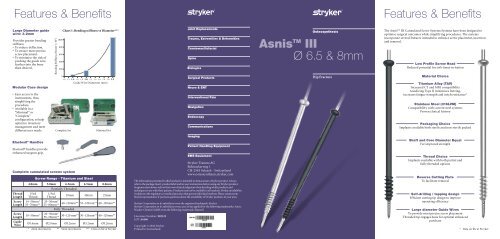
<strong>Asnis</strong> TM <strong>III</strong><br />
Ø 6.5 & 8mm<br />
Hip Fracture<br />
The <strong>Asnis</strong> TM <strong>III</strong> Cannulated Screw Systems Systems have been designed to<br />
optimise surgical outcomes while simplifying procedures. The systems<br />
incorporate several features intended to enhance screw placement, insertion<br />
and removal.<br />
Low Profile Screw Head<br />
Reduced potential for soft-tissue irritation<br />
Material Choice<br />
Titanium Alloy (TAV)<br />
Increased CT and MRI compatibility<br />
Anodizing Type II minimises fretting,<br />
increases fatigue strength and notch resistance*<br />
Stainless Steel (316LVM)<br />
Compatibility with current steel systems<br />
Proven clinical history<br />
Packaging Choice<br />
Implants available both sterile and non-sterile packed<br />
Elastosil ® Handles<br />
Elastosil® handles provide<br />
enhanced surgeon grip.<br />
Complete cannulated screws system<br />
Thread<br />
Length<br />
Screw<br />
Length<br />
4.0mm 5.0mm 6.5mm 6.5mm 8.0mm<br />
1/3rd<br />
Thread<br />
14−50mm*<br />
55−70mm**<br />
Partially Threaded<br />
1/3rd<br />
Thread<br />
20mm 40mm 25mm<br />
20−50mm*<br />
55−80mm**<br />
Screw<br />
Length 10−50mm* 20−50mm*<br />
55−70mm**<br />
Guide<br />
Wire<br />
Screw Range - Titanium and Steel<br />
40−120mm** 55−120mm** 40−120mm**<br />
<strong>Stryker</strong> Trauma AG<br />
Bohnackerweg 1<br />
CH-2545 Selzach - Switzerland<br />
www.osteosynthesis.stryker.com<br />
The information presented in this brochure is intended to demonstrate a <strong>Stryker</strong> product. Always<br />
refer to the package insert, product label and/or user instructions before using any <strong>Stryker</strong> product.<br />
Surgeons must always rely on their own clinical judgment when deciding which products and<br />
techniques to use with their patients. Products may not be available in all markets. Product availability<br />
is subject to the regulatory or medical practices that govern individual markets. Please contact your<br />
<strong>Stryker</strong> representative if you have questions about the availability of <strong>Stryker</strong> products in your area.<br />
<strong>Stryker</strong> Corporation or its subsidiary owns the registered trademark: <strong>Stryker</strong><br />
<strong>Stryker</strong> Corporation or its subsidiary owns, uses or has applied for the following trademarks: <strong>Asnis</strong>.<br />
Wacker-Chemie GmbH owns the following trademark: Elastosil<br />
Shaft and Core Diameter Equal<br />
For improved strength<br />
Thread Choice<br />
Implants available with both partial and<br />
fully threaded options<br />
Reverse Cutting Flute<br />
To facilitate removal<br />
Self-drilling / tapping design<br />
Efficient cutting tip design to improve<br />
operating efficiency<br />
Fully Threaded<br />
Large diameter Guide Wires<br />
To provide most precise screw placement<br />
30−120 mm** 30−120mm** 40−120mm**<br />
Literature Number: 982325<br />
Threaded tip engages bone for optimal enhanced<br />
LOT A4406<br />
purchase<br />
Ø1.4mm Ø2.0mm Ø3.2mm Ø3.2mm Ø3.2mm<br />
Copyright © 2006 <strong>Stryker</strong><br />
* 2mm increments ** 5mm increments *** Data on file at <strong>Stryker</strong> Printed in Switzerland<br />
* Data on file at <strong>Stryker</strong>
General Information<br />
Main Indication<br />
Other Indications<br />
Garden Classification: The most commonly used<br />
classification for intracapsular Hip Fractures<br />
Intracapsular Hip Fracture<br />
Step 2:<br />
Screw length measurement<br />
Garden I<br />
• Incomplete Fx<br />
• Stable<br />
Garden II<br />
• Complete but not displaced Fx<br />
• Considered as stable<br />
Performed with the direct reading<br />
depth gauge.<br />
This measurement will place the<br />
screw at the tip of the guide wire.<br />
If “in-between” sizes, use the<br />
shorter length.<br />
If compression is needed, consider<br />
the length of expected compression<br />
and choose an appropriately<br />
shorter screw.<br />
Garden <strong>III</strong><br />
• Complete & partially displaced<br />
subcapital Fx<br />
• Unstable<br />
Garden IV<br />
• Complete & fully displaced Fx<br />
• Unstable<br />
The patient is placed in a supine position on a fracture table<br />
Displaced fracture have to be reduced first.<br />
A straight lateral incision is made, starting at the flare of the greater trochanter<br />
and extending distally. The Fascia Lata and vastus lateralis are then split in line<br />
with the incision.<br />
Step 1:<br />
Guide Wire Insertion<br />
Step 3:<br />
Screw placement<br />
A cannulated screw is placed<br />
over each guide wire using the<br />
cannulated screwdriver.<br />
A self-drilling, self-tapping<br />
screw tip readily allows bone<br />
penetration.<br />
Pelvic sacroiliac joint disruption<br />
Dorsal pelvic ring fractures<br />
Density of trabecular bone in the femoral head<br />
Tension lines<br />
F<br />
Compression lines<br />
Anterior<br />
Superior<br />
Anterior<br />
Inferior<br />
82% 78%<br />
61%<br />
100%<br />
YIELD STRENGTH DISRIBUTION*<br />
The greatest yield strength is<br />
found in areas B F<br />
and C.<br />
52%<br />
“Screw thread fixation in the head is dependent<br />
on the density of the trabecular bone.<br />
Screw threads placed in the middle and superior<br />
head have superior holding power to those in an<br />
inferior position” **.<br />
* <strong>Stryker</strong> Osteosynthesis Science&Technology Department - “Positioning the lag screw”<br />
** Cannulated Screw Fixation - Book ISBN 0-387-94463-X (Springer) -<br />
STANLEY E. ASNIS & RICHARD F. KYLE<br />
A<br />
E<br />
Posterior<br />
Superior<br />
Posterior<br />
Inferior<br />
B<br />
D<br />
C<br />
In the AP view, using image<br />
intensification, the most inferior<br />
guide wire is passed just above the<br />
calcar, into the inferior femoral head.<br />
In the lateral view, this guide wire<br />
should stay in the mid-line of the<br />
femoral head and neck.<br />
Anteversion must be checked.<br />
In the case of dense cortical bone, the<br />
lateral femoral cortex can be opened<br />
with a 3.2mm drill bit.<br />
Drill guides for single, parallel,<br />
or multiple screw positioning<br />
options<br />
5mm<br />
Cross section of the femoral neck<br />
showing guide wire placement.<br />
Anterior<br />
Superior<br />
Inferior<br />
Inverted Triangle<br />
Posterior<br />
Step 4:<br />
Verifying Final Position<br />
The final position of<br />
the screws is verified<br />
using image<br />
intensification<br />
(AP / Lateral views).<br />
Guide wires are removed.<br />
The incision is closed.<br />
Please note: Guide wires are single use.<br />
Make sure to discard all used guide wires.<br />
Step 5:<br />
Screw Removal<br />
Be sure to use the <strong>Asnis</strong> TM <strong>III</strong> solid screwdriver to remove <strong>Asnis</strong> TM <strong>III</strong> screws.<br />
Never use a worn, damaged or cannulated screwdriver.<br />
The screw reverse cutting flutes may facilitate the re-cutting of the femoral<br />
cortex “from inside out” to allow for the passage of the threads.<br />
This flyer displays selected key points and is not substitute for the full operative<br />
technique manual.<br />
Intracapsular Hip fractures<br />
Femoral condyles fractures<br />
Tibial plateau fractures<br />
Ankle arthrodesis<br />
Subtalar fusion


