AxSOS Targeting System Distal Lateral Femur Operative - Stryker
AxSOS Targeting System Distal Lateral Femur Operative - Stryker AxSOS Targeting System Distal Lateral Femur Operative - Stryker
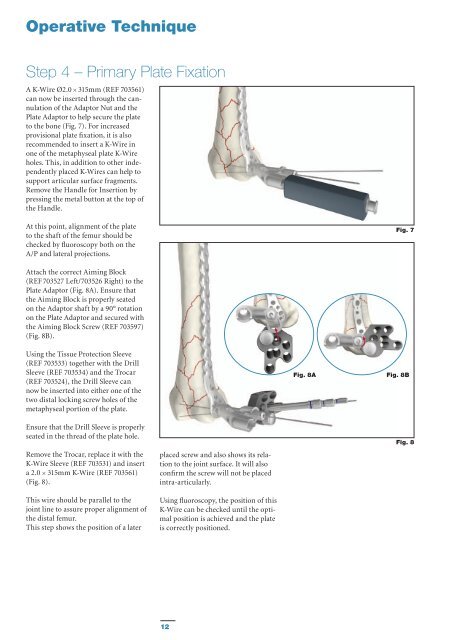
Operative Technique Step 4 – Primary Plate Fixation A K-Wire Ø2.0 × 315mm (REF 703561) can now be inserted through the cannulation of the Adaptor Nut and the Plate Adaptor to help secure the plate to the bone (Fig. 7). For increased provisional plate fixation, it is also recommended to insert a K-Wire in one of the metaphyseal plate K-Wire holes. This, in addition to other independently placed K-Wires can help to support articular surface fragments. Remove the Handle for Insertion by pressing the metal button at the top of the Handle. At this point, alignment of the plate to the shaft of the femur should be checked by fluoroscopy both on the A/P and lateral projections. Fig. 7 Attach the correct Aiming Block (REF 703527 Left/703526 Right) to the Plate Adaptor (Fig. 8A). Ensure that the Aiming Block is properly seated on the Adaptor shaft by a 90° rotation on the Plate Adaptor and secured with the Aiming Block Screw (REF 703597) (Fig. 8B). Using the Tissue Protection Sleeve (REF 703533) together with the Drill Sleeve (REF 703534) and the Trocar (REF 703524), the Drill Sleeve can now be inserted into either one of the two distal locking screw holes of the metaphyseal portion of the plate. Fig. 8A Fig. 8B Ensure that the Drill Sleeve is properly seated in the thread of the plate hole. Remove the Trocar, replace it with the K-Wire Sleeve (REF 703531) and insert a 2.0 × 315mm K-Wire (REF 703561) (Fig. 8). This wire should be parallel to the joint line to assure proper alignment of the distal femur. This step shows the position of a later placed screw and also shows its relation to the joint surface. It will also confirm the screw will not be placed intra-articularly. Using fluoroscopy, the position of this K-Wire can be checked until the optimal position is achieved and the plate is correctly positioned. Fig. 8 12
Operative Technique Correct proximal plate placement should also be re-confirmed at this point to make sure the plate shaft is properly aligned over the lateral surface of the femoral shaft. If the distal and axial alignment of the plate cannot be achieved, the K-Wires should be removed, the plate re-adjusted and the above procedure repeated until both the distal K-Wires and the plate are in the desired position. Do not remove K-Wires as a loss of plate position could result. The proximal end of the plate must now be secured using the most proximal hole of the shaft. Attach the Targeting Arm (REF 703529 Left/703528 Right) to the Plate Adaptor. Mark the skin at the most proximal hole using the Tissue Protection Sleeve (REF 703532) and make a small incision. Insert the Trocar with sharp tip (REF 703525) into the Tissue Protection Sleeve (REF 703532) and manipulate the assembly through the Targeting Arm and the stab incision until the tip of the Trocar is in contact with the plate. Push the Tissue Protection Sleeve further into the hole until the locking notches of the Tissue Protection Sleeve fully engage in the corresponding groove in the Targeting Arm (details see also step 6 shaft fixation). Essentially, this will securely lock the Tissue Protection Sleeve in the Targeting Arm. Ensure that the Sleeve Fixation Screw is orientated posteriorly as displayed on the Targeting Arm. Remove the Trocar and replace it with a Drill Sleeve (REF 703534) and Trocar Ø4.3mm (REF 703524) and manipulate the assembly into the plate hole. Ensure that the Drill Sleeve is fully engaged in the thread of the plate hole to create a stable construct between the Targeting Arm and the plate, providing sufficient stability for accurate screw targeting. Secure the Drill Sleeve by tightening the Sleeve Fixation Screw. Remove the Trocar. A 2.0 × 315mm K-Wire (REF 703561) can now be inserted using the K-Wire Sleeve (REF 703531) (Fig. 9). Alternatively, the 4.3mm Calibrated Drill (REF 703541) can be inserted bi-cortically. Leave the Drill Bit in place for primary plate stabilization (Fig. 9A). Fig. 9A Fig. 9 13
- Page 1 and 2: Femur AxSOS KnifeLight Targeting Sy
- Page 3 and 4: Contents Page 1. Introduction 4 2.
- Page 5 and 6: Features & Benefits System The Dist
- Page 7 and 8: Operative Technique General Guideli
- Page 9 and 10: Operative Technique Step 1 - Pre-Op
- Page 11: Operative Technique Step 3 - Submus
- Page 15 and 16: Operative Technique Step 5 - Metaph
- Page 17 and 18: Operative Technique Final tightenin
- Page 19 and 20: Operative Technique b) Locking Scre
- Page 21 and 22: Ordering Information - Implants Dis
- Page 23 and 24: Ordering Information - Targeting In
- Page 25 and 26: Ordering Information - Instruments
- Page 27 and 28: Notes 27
<strong>Operative</strong> Technique<br />
Step 4 – Primary Plate Fixation<br />
A K-Wire Ø2.0 × 315mm (REF 703561)<br />
can now be inserted through the cannulation<br />
of the Adaptor Nut and the<br />
Plate Adaptor to help secure the plate<br />
to the bone (Fig. 7). For increased<br />
provisional plate fixation, it is also<br />
recommended to insert a K-Wire in<br />
one of the metaphyseal plate K-Wire<br />
holes. This, in addition to other independently<br />
placed K-Wires can help to<br />
support articular surface fragments.<br />
Remove the Handle for Insertion by<br />
pressing the metal button at the top of<br />
the Handle.<br />
At this point, alignment of the plate<br />
to the shaft of the femur should be<br />
checked by fluoroscopy both on the<br />
A/P and lateral projections.<br />
Fig. 7<br />
Attach the correct Aiming Block<br />
(REF 703527 Left/703526 Right) to the<br />
Plate Adaptor (Fig. 8A). Ensure that<br />
the Aiming Block is properly seated<br />
on the Adaptor shaft by a 90° rotation<br />
on the Plate Adaptor and secured with<br />
the Aiming Block Screw (REF 703597)<br />
(Fig. 8B).<br />
Using the Tissue Protection Sleeve<br />
(REF 703533) together with the Drill<br />
Sleeve (REF 703534) and the Trocar<br />
(REF 703524), the Drill Sleeve can<br />
now be inserted into either one of the<br />
two distal locking screw holes of the<br />
metaphyseal portion of the plate.<br />
Fig. 8A<br />
Fig. 8B<br />
Ensure that the Drill Sleeve is properly<br />
seated in the thread of the plate hole.<br />
Remove the Trocar, replace it with the<br />
K-Wire Sleeve (REF 703531) and insert<br />
a 2.0 × 315mm K-Wire (REF 703561)<br />
(Fig. 8).<br />
This wire should be parallel to the<br />
joint line to assure proper alignment of<br />
the distal femur.<br />
This step shows the position of a later<br />
placed screw and also shows its relation<br />
to the joint surface. It will also<br />
confirm the screw will not be placed<br />
intra-articularly.<br />
Using fluoroscopy, the position of this<br />
K-Wire can be checked until the optimal<br />
position is achieved and the plate<br />
is correctly positioned.<br />
Fig. 8<br />
12


