

AxSOS Locking Plate System - Stryker
AxSOS Locking Plate System - Stryker
AxSOS Locking Plate System - Stryker

Create successful ePaper yourself
Turn your PDF publications into a flip-book with our unique Google optimized e-Paper software.
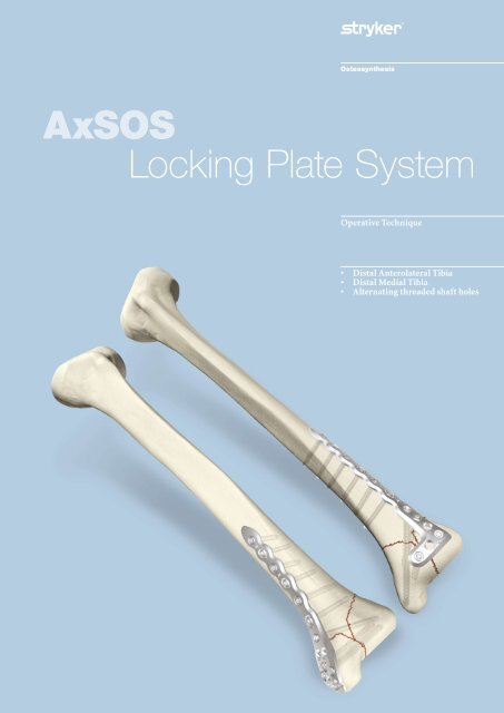
<strong>AxSOS</strong><br />
<strong>Locking</strong> <strong>Plate</strong> <strong>System</strong><br />
Operative Technique<br />
• Distal Anterolateral Tibia<br />
• Distal Medial Tibia<br />
• Alternating threaded shaft holes
This publication sets forth detailed<br />
recommended procedures for using<br />
<strong>Stryker</strong> Osteosynthesis devices and<br />
instruments.<br />
It offers guidance that you should<br />
heed, but, as with any such technical<br />
guide, each surgeon must consider<br />
the particular needs of each patient<br />
and make appropriate adjustments<br />
when and as required.<br />
A workshop training is required prior<br />
to first surgery.<br />
All non-sterile devices must be<br />
cleaned and sterilized before use.<br />
Follow the instructions provided in<br />
our reprocessing guide (L24002000).<br />
Multi-component instruments must<br />
be disassembled for cleaning. Please<br />
refer to the corresponding assembly/<br />
disassembly instructions.<br />
See package insert (V15011 and<br />
V15013) for a complete list of potential<br />
adverse effects, contraindications,<br />
warnings and precautions. The<br />
surgeon must discuss all relevant<br />
risks, including the finite lifetime of<br />
the device, with the patient, when<br />
necessary.<br />
Warning:<br />
All bone screws referenced in<br />
this document here are not<br />
approved for screw attachment or<br />
fixation to the posterior elements<br />
(pedicles) of the cervical, thoracic<br />
or lumbar spine.<br />
2
Contents<br />
Page<br />
1. Introduction 4<br />
2. Features & Benefits 5<br />
3. Indications, Precautions & Contraindications 6<br />
Indications 6<br />
Precautions 6<br />
Contraindications 6<br />
4. Operative Technique 7<br />
General Guidlines 7<br />
Step 1 – Pre-Operative Planning 9<br />
Step 2 – Pre-Operative <strong>Locking</strong> Insert Application 9<br />
Step 2a – <strong>Locking</strong> Insert Extraction 10<br />
Step 2b – Intra-Operative <strong>Locking</strong> Insert Application 10<br />
Step 3 – Aiming Block/<strong>Plate</strong> Insertion Handle Assembly 11<br />
Step 4 – <strong>Plate</strong> Application 11<br />
Step 5 – Primary <strong>Plate</strong> Fixation Distal 12<br />
Step 6 – Primary <strong>Plate</strong> Fixation – Proximal (Optional) 13<br />
Step 7 – Metaphyseal <strong>Locking</strong> 13<br />
Step 8 – Shaft Fixation 16<br />
Option 1 – Standard Screws 16<br />
Option 2 – <strong>Locking</strong> Screws 17<br />
Step 9 - Kick-Stand Screw Placement 17<br />
Sub-Muscular Insertion Technique 18<br />
5. Additional Tips 21<br />
Ordering Information – Implants 22<br />
Ordering Information – Instruments 24<br />
Ordering Information – 4.0mm Instruments 26<br />
Additional Information 27<br />
HydroSet Injectable HA 27<br />
Indications 27<br />
Advantages 27<br />
3
Introduction<br />
The <strong>AxSOS</strong> <strong>Locking</strong> <strong>Plate</strong> <strong>System</strong><br />
is designed to treat periarticular<br />
or intra-articular fractures of the<br />
Proximal Humerus, Distal Femur,<br />
Proximal Tibia and the Distal Tibia.<br />
The system design is based on clinical<br />
input from an international panel of<br />
experienced surgeons, data from literature,<br />
and both practical and biomechanical<br />
testing.<br />
The anatomical shape, the fixed screw<br />
trajectory, and high surface quality<br />
take into account the current demands<br />
of clinical physicians for appropriate<br />
fixation, high fatigue strength, and<br />
minimal soft tissue damage.<br />
This Operative Technique contains a<br />
simple step-by-step procedure for the<br />
implantation of the the anterolateral<br />
and medial distal tibial plates<br />
Distal Anterolateral Tibial <strong>Plate</strong><br />
Distal Medial Tibial <strong>Plate</strong><br />
Proximal Lateral Tibial <strong>Plate</strong><br />
Proximal Humeral <strong>Plate</strong><br />
Distal Lateral Femoral <strong>Plate</strong><br />
Distal Anterolateral Tibial <strong>Plate</strong><br />
4
Features & Benefits<br />
<strong>System</strong><br />
The anterolateral and the medial<br />
distal Tibial <strong>Plate</strong>s are designed with<br />
optimized fixed-angled screw trajectories<br />
in the metaphyseal part and<br />
straight fixed-angled screw trajectories<br />
which provide increased biomechanical<br />
stability. This helps prevent loss of<br />
reduction.<br />
Instruments<br />
• Simple technique, with easy to use<br />
instrumentation.<br />
• Compatible with MIPO<br />
(Minimally Invasive <strong>Plate</strong> Osteosynthesis)<br />
technique using state of<br />
the art instrumentation.<br />
Range<br />
Longer plates cover a wider range of<br />
fractures.<br />
‘Waisted’ plate shape<br />
Uniform load transfer.<br />
Rounded & Tapered <strong>Plate</strong> End<br />
Helps facilitate sliding of plates<br />
sub-muscularly.<br />
Shaft Holes -<br />
Standard or <strong>Locking</strong><br />
• Compression, neutral or buttress<br />
fixation.<br />
• Accept standard 3.5/4.0mm<br />
SPS screws.<br />
• Accept locking insert for axially<br />
stable screws.<br />
• Pre-drilled locking holes allow axially<br />
stable screw placement.<br />
Innovative <strong>Locking</strong> Screw design<br />
• Screw is guided into plate.<br />
• The single thread screw design<br />
allows easy insertion into the plate,<br />
reducing any potential for cross<br />
threading or cold welding.<br />
Anatomically contoured<br />
• Little or no bending required.<br />
• May reduce OR time.<br />
• Facilitates/allows for better soft<br />
tissue coverage<br />
K-Wire/Reduction/Suture holes<br />
Primary/temporary plate and fracture<br />
fixation.<br />
Kick-Stand Screw<br />
Aimed at medial/lateral fragment to<br />
provide strong triangular fixation.<br />
Unthreaded Freedom Holes<br />
• Freehand placement of screws.<br />
• Lag screw possibility.<br />
Monoaxial holes (3)<br />
Allows axially stable screw placement,<br />
bringing stability to construct.<br />
Monoaxial holes (4)<br />
Allow axially stable screw placement,<br />
bringing stability to construct.<br />
Aiming Blocks<br />
Facilitates the placement of the Drill<br />
Sleeve.<br />
5
Indications, Precautions & Contraindications<br />
Indications<br />
The indication for use of these internal<br />
fixation devices includes metaphyseal<br />
extra and intra-articular fractures of<br />
the distal tibia.<br />
Precautions<br />
<strong>Stryker</strong> Osteosynthesis systems have<br />
not been evaluated for safety and use<br />
in MR environment and have not been<br />
tested for heating or migration in the<br />
MR environment, unless specified<br />
otherwise in the product labeling or<br />
respective operative technique.<br />
Contraindications<br />
The physician's education, training<br />
and professional judgement must be<br />
relied upon to choose the most appropriate<br />
device and treatment. The<br />
following contraindications may be of<br />
a relative or absolute nature, and must<br />
be taken into account by the attending<br />
surgeon:<br />
• Any active or suspected latent<br />
infection or marked local inflammation<br />
in or about the affected<br />
area.<br />
• Compromised vascularity that<br />
would inhibit adequate blood<br />
supply to the fracture or the operative<br />
site.<br />
• Bone stock compromised by disease,<br />
infection or prior implantation<br />
that can not provide adequate<br />
support and/or fixation of the<br />
devices.<br />
• Material sensitivity, documented or<br />
suspected.<br />
• Obesity. An overweight or obese<br />
patient can produce loads on the<br />
implant that can lead to failure<br />
of the fixation of the device or to<br />
failure of the device itself.<br />
• Patients having inadequate tissue<br />
coverage over the operative site.<br />
• Implant utilisation that would<br />
interfere with anatomical structures<br />
or physiological performance.<br />
• Any mental or neuromuscular<br />
disorder which would create an<br />
unacceptable risk of fixation failure<br />
or complications in postoperative<br />
care.<br />
• Other medical or surgical conditions<br />
which would preclude the<br />
potential benefit of surgery.<br />
Detailed information is included in the<br />
instructions for use being attached to<br />
every implant.<br />
See package insert for a complete list of<br />
potential adverse effects and contraindications.<br />
The surgeon must discuss<br />
all relevant risks, including the finite<br />
lifetime of the device, with the patient,<br />
when necessary.<br />
Caution:<br />
Bone Screws are not intended for<br />
screw attachment or fixation to<br />
the posterior elements (pedicles)<br />
of the cervical, thoracic or lumbar<br />
spine.<br />
6
Operative Technique<br />
General Guidelines<br />
Patient Positioning:<br />
Surgical Approach Lateral:<br />
Surgical Approach Medial:<br />
Instrument / Screw Set:<br />
Supine<br />
Between lateral Tibia and Fibula<br />
Distal oblique 1cm proximal to the medial Malleolus<br />
4.0mm<br />
Reduction<br />
Anatomical reduction of the fracture<br />
should be performed either by<br />
direct visualization with the help of<br />
percutaneous reduction clamps and/<br />
or K-Wires or alternatively a bridging<br />
external fixator can aid indirect<br />
reduction. Fracture reduction of the<br />
articular surface should be confirmed<br />
by direct vision, or fluoroscopy. Use<br />
K-Wires as necessary to temporarily<br />
secure the reduction.<br />
Typically, K-Wires set parallel to the<br />
joint axis will not only act to hold and<br />
support the reduction, but also help to<br />
visualize/identify the joint. Care must<br />
be taken that these do not interfere<br />
with the required plate and screw<br />
positions.<br />
Bending<br />
In most cases, the pre-contoured plate<br />
will fit without the need for further<br />
bending. However, should additional<br />
bending of the plate be required (generally<br />
at the junction from the metaphysis<br />
to the shaft) the Bending Irons<br />
(REF 702756) should be used. Bending<br />
of the plate in the region of the<br />
metaphyseal locking holes will affect<br />
the ability to correctly seat the <strong>Locking</strong><br />
Screws into the plate and is therefore<br />
not permitted.<br />
<strong>Plate</strong> contouring in the shaft region<br />
below the oblong hole is not recommended.<br />
<strong>Plate</strong> contouring will affect<br />
the ability to place a <strong>Locking</strong> Insert<br />
into the shaft holes adjacent to the<br />
bending point.<br />
Consideration must also be taken<br />
when positioning independent lag<br />
screws prior to plate placement to<br />
ensure that they do not interfere with<br />
the planned plate location or <strong>Locking</strong><br />
Screw trajectories.<br />
If any large bony defects are present<br />
they should be filled by either bone<br />
graft or bone substitute material.<br />
Note:<br />
If a sub-muscular technique has<br />
been used please see the relevant<br />
section later in this guide.<br />
7
Operative Technique<br />
General Guidelines<br />
<strong>Locking</strong> Screw Measurement<br />
There are four options to obtain<br />
the proper <strong>Locking</strong> Screw length<br />
as illustrated below.<br />
Correct Screw Selection<br />
Note:<br />
Select a screw approximately<br />
2-3mm shorter than the measured<br />
length to avoid screw penetration<br />
to the opposite cortex.<br />
Add 2-3mm to measured length for<br />
optimal bi-cortical shaft fixation.<br />
Measurement Options<br />
Measure off K-Wire<br />
Read off drill bit calibration<br />
Conventional direct measurement<br />
Measure off the end of drill bit<br />
8
Operative Technique<br />
Step 1 – Pre-Operative Planning<br />
Use of the X-Ray Template<br />
(REF 981083 for lateral or 981082 for<br />
medial) or <strong>Plate</strong> Trial (REF 702797<br />
for lateral or REF 702795 for medial<br />
respectively) in association with fluoroscopy<br />
can assist in the selection of an<br />
appropriately sized implant<br />
(Fig 1 - 1B).<br />
If the <strong>Plate</strong> Trial is more than 90mm<br />
away from the bone, e.g. with obese<br />
patients, a magnification factor<br />
of 10-15% will occur and must be<br />
compensated for. Final intraoperative<br />
verification should be made to ensure<br />
correct implant selection.<br />
<strong>AxSOS</strong> <strong>Locking</strong> <strong>Plate</strong> <strong>System</strong><br />
Distal Medial Tibial <strong>Plate</strong> TS<br />
Scale: 1.15 : 1<br />
Magnification: 15%<br />
<strong>AxSOS</strong> <strong>Locking</strong> <strong>Plate</strong> <strong>System</strong><br />
Distal Anterolateral Tibial <strong>Plate</strong> TS<br />
Scale: 1.15 : 1<br />
Magnification: 15%<br />
A-P View M-L View A-P View<br />
M-L View<br />
16 Hole<br />
16 Hole<br />
Ø 4mm <strong>Locking</strong> Screw, Self T a pping<br />
REF 370514/-595<br />
14 Hole<br />
Ø 4mm <strong>Locking</strong> Screw, Self T a pping<br />
REF 370514/-595<br />
14 Hole<br />
Ø 3.5mm Cortical Screw, Self Tapping<br />
REF 338614/-695<br />
12 Hole<br />
Ø 3.5mm Cortical Screw, Self Tapping<br />
REF 338614/-695<br />
12 Hole<br />
Ø 4.0mm Cancellous Screw<br />
Partial Thread: REF 345514/-595<br />
Full Thread: REF 345414/-495<br />
10 Hole<br />
Ø 4.0mm Cancellous Screw<br />
Partial Thread: REF 345514/-595<br />
Full Thread: REF 345414/-495<br />
10 Hole<br />
8 Hole<br />
8 Hole<br />
Please Note:<br />
Please Note:<br />
Due to the multi-planar positioning of the screws the<br />
determination of the corresponding screw length and<br />
angle is difficult by means of single planar x-rays in<br />
general.<br />
All dimensions resulting from the use of this template<br />
has to be verified intraoperatively, to ensure proper<br />
implant selection.<br />
6 Hole<br />
4 Hole<br />
Left<br />
Right<br />
Left<br />
Right<br />
REF 981082 Rev. 0<br />
REF 981083 Rev. 0<br />
Fig. 1 Fig. 1A Fig. 1B<br />
Step 2 – Pre-Operative <strong>Locking</strong> Insert Application<br />
If additional <strong>Locking</strong> Screws are<br />
chosen for the plate shaft, pre-operative<br />
insertion of <strong>Locking</strong> Inserts is<br />
recommended.<br />
A 4.0mm <strong>Locking</strong> Insert (REF 370002)<br />
is attached to the <strong>Locking</strong> Insert<br />
Inserter (REF 702762) and placed into<br />
the chosen holes in the shaft portion<br />
of the plate (Fig. 2). Ensure that the<br />
<strong>Locking</strong> Insert is properly placed. The<br />
Inserter should then be removed<br />
(Fig. 2A).<br />
Note:<br />
Do not place <strong>Locking</strong> Inserts with<br />
the Drill Sleeve.<br />
Fig. 2<br />
It is important to note that if a Temporary<br />
<strong>Plate</strong> Holder is to be used for<br />
primary proximal plate fixation, then<br />
a <strong>Locking</strong> Insert must not be placed in<br />
the same hole as the Temporary <strong>Plate</strong><br />
Holder (See Step 6).<br />
Fig. 2A<br />
9
Operative Technique<br />
Step 2a – <strong>Locking</strong> Insert Extraction<br />
Should removal of a <strong>Locking</strong> Insert<br />
be required for any reason, then the<br />
following procedure should be used.<br />
Thread the central portion (A) of the<br />
<strong>Locking</strong> Insert Extractor (REF 702767)<br />
into the <strong>Locking</strong> Insert that you wish<br />
to remove until it is fully seated<br />
(Fig. 2B).<br />
B<br />
A<br />
Then turn the outer sleeve/collet (B)<br />
clockwise until it pulls the <strong>Locking</strong><br />
Insert out of the plate (Fig. 2C).<br />
The <strong>Locking</strong> Insert should then be<br />
discarded, as it should not be reused.<br />
Fig. 2B<br />
Fig. 2C<br />
Step 2b – Intra-Operative <strong>Locking</strong> Insert Application<br />
If desired, a <strong>Locking</strong> Insert can be<br />
applied in a non-threaded hole in the<br />
shaft of the plate intra-operatively by<br />
using the <strong>Locking</strong> Insert Forceps<br />
(REF 702968), Centering Pin<br />
(REF 702673), Adaptor for Centering<br />
Pin (REF 702675), and Guide for<br />
Centering Pin (REF 702671).<br />
First, the Centering Pin is inserted<br />
through the chosen hole using the<br />
Adaptor and Guide (Fig. 3A). It is<br />
important to use the Guide as this<br />
centers the core hole for <strong>Locking</strong> Screw<br />
insertion after the <strong>Locking</strong> Insert is<br />
applied. After inserting the Centering<br />
Pin bi-cortically, remove the Adaptor<br />
and Guide.<br />
Fig. 3A<br />
Next, place a <strong>Locking</strong> Insert on the<br />
end of the Forceps and slide the instrument<br />
over the Centering Pin down to<br />
the hole.<br />
Last, apply the <strong>Locking</strong> Insert by triggering<br />
the forceps handle. Push the<br />
button on the Forceps to remove the<br />
device . At this time, remove the Centering<br />
Pin (Fig. 3B).<br />
Fig. 3B<br />
10
Operative Technique<br />
Step 3 – Aiming Block/<strong>Plate</strong> Insertion Handle Assembly<br />
Screw the appropriate Aiming Block<br />
(REF 702723/702722 for lateral or<br />
702725/702724 for medial respectively)<br />
to the plate using the Screwdriver T15<br />
(REF 702747).<br />
If desired, the Handle for <strong>Plate</strong> Insertion<br />
(REF 702778) can now be attached<br />
to help facilitate plate positioning and<br />
sliding of longer plates sub-muscularly<br />
(Fig 4).<br />
Fig. 4<br />
Step 4 – <strong>Plate</strong> Application<br />
After skin incision and anatomical<br />
reduction is achieved, apply and<br />
manipulate the plate until optimal<br />
position in relation to the joint is<br />
achieved (approx. 5mm above the<br />
anterior articular surface).<br />
This helps to ensure that the most<br />
distal <strong>Locking</strong> Screws are directly<br />
supporting the joint surface (Fig. 5).<br />
Fig. 5 – Medial View<br />
Fig. 5 – Lateral View<br />
11
Operative Technique<br />
Step 5 – Primary <strong>Plate</strong> Fixation Distal<br />
The K-Wire holes in the plates allow<br />
temporary plate fixation in the metaphysis<br />
and the shaft part.<br />
Using the K-Wire Sleeve (REF 702702)<br />
in conjunction with the Drill Sleeve<br />
(REF 702707), a 2.0 × 230mm K-Wire<br />
can then be inserted into one of the<br />
distal <strong>Locking</strong> Screw holes (Fig. 6).<br />
This step shows the position of the<br />
screw in relation to the joint surface<br />
and confirms the screw will not be<br />
intra-articular.<br />
Using fluoroscopy, the position of<br />
this K-Wire can be checked until the<br />
optimal position is achieved and the<br />
plate is correctly positioned. Correct<br />
proximal placement should also be<br />
reconfirmed at this point to make sure<br />
the plate shaft is properly aligned over<br />
the lateral surface of the tibial shaft<br />
(Fig. 7). Secure the position by inserting<br />
a K-Wire in the hole above the<br />
Kick-Stand Screw hole.<br />
Fig. 6<br />
self-tapping 3.5mm cortical Screw<br />
or a 4.0mm cancellous Screw is then<br />
inserted using the 2.5mm hexagonal<br />
Screwdriver (REF 702841) together<br />
with the Screw Holding Sleeve (REF<br />
702490) (Fig. 8).<br />
If inserting a Cancellous Screw, the<br />
near cortex must be pre-tapped using<br />
the Tap (REF 702805) and the Teardrop<br />
Handle (REF 702428).<br />
Any K-Wires in the shaft can be<br />
removed upon adequate screw fixation.<br />
If the distal and axial alignment of<br />
the plate cannot be acheived, the<br />
K-Wires should be removed, the plate<br />
readjusted, and the above procedure<br />
repeated until both the distal K-Wire<br />
and the plate are in the desired position.<br />
Additional 2.0 × 150mm K-Wires<br />
(REF 390192) can be inserted in the<br />
K-Wire holes distal to the locking holes<br />
to further help secure the plate to the<br />
bone and also support depressed areas<br />
in the articular surface.<br />
Fig. 7<br />
Do not remove the Drill Sleeve and<br />
K-Wire Sleeve at this point as it will<br />
cause a loss of the plate position.<br />
Remove the Handle for Insertion by<br />
pressing the metal button at the end.<br />
Using a 2.5mm Drill Bit (REF 700347-<br />
125mm or REF 700355- 230mm) and<br />
Double Drill Guide (REF 702418), drill<br />
a core hole to the appropriate depth in<br />
the first non-threaded shaft hole above<br />
the most proximal fracture line.<br />
The length is then measured using<br />
the Depth Gauge for Standard Screws<br />
(REF 702879) and an appropriate<br />
Fig. 8<br />
12
Operative Technique<br />
Step 6 – Primary <strong>Plate</strong> Fixation – Proximal (Optional)<br />
The proximal end of the plate can<br />
now be secured. This can be achieved<br />
through one of four methods:<br />
• A K-Wire inserted in the proximal<br />
shaft K-Wire hole.<br />
• A 3.5mm Cortex Screw or 4.0mm<br />
cancellous Screw using the standard<br />
technique.<br />
• A 4.0mm <strong>Locking</strong> Screw in the<br />
pre-threaded locking holes or with<br />
a <strong>Locking</strong> Insert in the standard<br />
holes (see Step 8 – Shaft Fixation).<br />
• The Temporary <strong>Plate</strong> Holder<br />
(REF 702776) in the last<br />
unthreaded shaft hole.<br />
In addition to providing temporary<br />
fixation, the <strong>Plate</strong> Holder pushes the<br />
plate to the bone. Also, it has a self<br />
drilling, self tapping tip for quick<br />
insertion into cortical bone.<br />
To help prevent thermal necrosis<br />
during the drilling stage, it is recommended<br />
that this device is inserted<br />
by hand. Once the device has been<br />
inserted through the far cortex, the<br />
threaded outer sleeve/collet is turned<br />
clockwise until the plate is in contact<br />
with the bone (Fig. 9).<br />
The core diameter of this instrument<br />
is 2.4mm to allow a 3.5mm cortical<br />
Screw to be subsequently inserted<br />
in the same plate hole.<br />
Note:<br />
A <strong>Locking</strong> Insert and <strong>Locking</strong><br />
Screw should not be used in the<br />
hole where the Temporary <strong>Plate</strong><br />
Holder is used.<br />
Fig. 9<br />
Step 7 – Metaphyseal <strong>Locking</strong><br />
<strong>Locking</strong> Screws cannot act as Lag<br />
Screws. Should interfragmentary compression<br />
be desired, a 4.0mm Standard<br />
cancellous Screw or a 3.5mm Standard<br />
Cortex Screw must first be placed in<br />
the unthreaded metaphyseal plate<br />
holes (Fig. 10) prior to the placement<br />
of any <strong>Locking</strong> Screws. Measure the<br />
length of the screw using the Depth<br />
Gauge for Standard Screws (REF<br />
702879), and pre-tap the near cortex<br />
with the Tap (REF 702805) if a cancellous<br />
Screw is used.<br />
Consideration must also be taken<br />
when positioning this screw to ensure<br />
that it does not interfere with the given<br />
<strong>Locking</strong> Screw trajectories. (Fig 11).<br />
Fig. 10 Fig. 11<br />
13
Operative Technique<br />
Fixation of the metaphyseal portion<br />
of the plate can be started using the<br />
preset K-Wire in one of the distal locking<br />
hole as described in Step 5.<br />
The length of the screw can be taken<br />
by using the K-Wire side of the Drill/<br />
K-Wire Measure Gauge (REF 702712).<br />
(See locking screw Measurement<br />
Guidelines on Page 8).<br />
Remove the K-Wire and K-Wire Sleeve<br />
leaving the Drill Sleeve in place.<br />
A 3.1mm Drill (REF 702742) is then<br />
used to drill the core hole for the <strong>Locking</strong><br />
Screw (Fig. 12).<br />
Using Fluoroscopy, check the correct<br />
depth of the drill, and measure the<br />
length of the screw using the Depth<br />
Gauge for <strong>Locking</strong> Screws (REF<br />
702884).<br />
Fig. 12<br />
The Drill Sleeve should now be<br />
removed, and the correct length<br />
4.0mm <strong>Locking</strong> Screw is inserted using<br />
the Screwdriver T15 (REF 702747) and<br />
Screw Holding Sleeve (REF 702732)<br />
(Fig. 13).<br />
<strong>Locking</strong> Screws should initially be<br />
inserted manually to ensure proper<br />
alignment.<br />
Note:<br />
If the <strong>Locking</strong> Screw thread does<br />
not engage immediately in the<br />
plate thread, reverse the screw a<br />
few turns and re-insert the screw<br />
once it is properly aligned.<br />
Fig. 13<br />
14
Operative Technique<br />
Final tightening of <strong>Locking</strong> Screws<br />
should always be performed manually<br />
using the Torque Limiting Attachment<br />
(REF 702750) together with the Solid<br />
Screwdriver T15 (REF 702753) and<br />
T-Handle (REF 702427) (Fig. 14).<br />
This helps to prevent over-tightening<br />
of <strong>Locking</strong> Screws, and also ensures<br />
that these Screws are tightened to<br />
a maximum torque of 4.0Nm. The<br />
device will click when the torque<br />
reaches 4Nm.<br />
Note:<br />
The Torque Limiters require<br />
routine maintenance. Refer to the<br />
instructions for Maintenance of<br />
Torque Limiters (REF V15020).<br />
"Click"<br />
If inserting <strong>Locking</strong> Screws under<br />
power, make sure to use a low speed<br />
drill setting to avoid damage to the<br />
screw/plate interface. Perform final<br />
tightening by hand.<br />
Fig. 14<br />
The remaining distal <strong>Locking</strong> Screws<br />
are inserted following the same<br />
technique with or without the use of a<br />
K-Wire.<br />
Always use the Drill Sleeve<br />
(REF 702707) when drilling for locking<br />
holes.<br />
To ensure maximum stability, it is<br />
recommended that all locking holes<br />
are filled with a <strong>Locking</strong> Screw of the<br />
appropriate length.<br />
15
Operative Technique<br />
Step 8 – Shaft Fixation<br />
The shaft holes of this plate have<br />
been designed to accept either 3.5mm<br />
Standard Cortical Screws or 4.0mm<br />
<strong>Locking</strong> Screws. These screws can be<br />
inserted in the predrilled locking holes<br />
or together with the corresponding<br />
<strong>Locking</strong> Inserts.<br />
Note:<br />
If a combination of Standard and<br />
<strong>Locking</strong> Screws is used in the<br />
shaft, the plate fixation should<br />
begin with Standard Cortical<br />
Screws prior to the <strong>Locking</strong><br />
Screws. Always lag before you<br />
lock.<br />
Locked Hole<br />
70° Axial Angulation 14° Transverse<br />
Angulation<br />
(in non-locked holes only!)<br />
Option 1 – Standard Screws<br />
3.5mm Standard cortical Screws can<br />
be placed in Neutral, Compression or<br />
Buttress positions as desired using<br />
the relevant Drill Guides and the standard<br />
technique.<br />
These screws can also act as Lag<br />
Screws.<br />
Note:<br />
This is only possible in nonthreaded<br />
holes.<br />
Buttress<br />
Compression<br />
Neutral<br />
16
Operative Technique<br />
Option 2 – <strong>Locking</strong> Screws<br />
4.0mm <strong>Locking</strong> Screws can be placed<br />
in the threaded shaft holes or holes<br />
with pre-placed <strong>Locking</strong> Inserts.<br />
Use the Drill Sleeve (REF 702707) to<br />
pre-drill the core hole for subsequent<br />
<strong>Locking</strong> Screw placement. The Drill<br />
Sleeve should be fully inserted into the<br />
pre-threaded hole or <strong>Locking</strong> Insert to<br />
ensure initial fixation of the <strong>Locking</strong><br />
Insert into the plate.<br />
T15 (REF 702753) and the Screw Holding<br />
Sleeve (REF 702732) together with<br />
the Torque Limiting Attachment<br />
(REF 702750) and the T-Handle<br />
(REF 702427).<br />
Note:<br />
Ensure that the screwdriver tip is<br />
fully seated in the screw head, but<br />
do not apply axial force during<br />
final tightening.<br />
A 3.1mm Drill Bit (REF 702742) is<br />
used to drill through both cortices<br />
(Fig. 15).<br />
Avoid any angulation or excessive force<br />
on the drill, as this could dislodge the<br />
<strong>Locking</strong> Insert.<br />
The screw measurement is then taken.<br />
The appropriate sized <strong>Locking</strong> Screw<br />
is then inserted using the Screwdriver<br />
Maximum stability of the <strong>Locking</strong><br />
Insert is achieved once the screw is<br />
fully seated and tightened to 4.0Nm.<br />
This procedure is repeated for all<br />
pre-threaded holes and holes with preplaced<br />
<strong>Locking</strong> Inserts.<br />
All provisional plate fixation devices<br />
(K-Wires, Temporary <strong>Plate</strong> Holder, etc)<br />
can now be removed.<br />
Fig. 15<br />
Step 9 – Kick-Stand Screw Placement<br />
The oblique ‘Kick-Stand’ <strong>Locking</strong><br />
Screw provides strong triangular fixation<br />
to the opposite fragments.<br />
It should be the last screw in the metaphyseal<br />
portion of the plate.<br />
It is advised that this screw is placed<br />
with the assistance of fluoroscopy to<br />
prevent joint penetration and impingement<br />
with the distal Screws (Fig. 16)<br />
(See Step 6 for insertion guidelines).<br />
The Aiming Block should now be<br />
removed.<br />
Fig. 16<br />
17
Operative Technique<br />
Sub-Muscular Insertion Technique<br />
When implanting longer plates, a minimally<br />
invasive technique can be used.<br />
The Soft Tissue Elevator (REF 702782)<br />
can be used to create a pathway for the<br />
implant (Fig. 17).<br />
The plate has a special rounded and<br />
tapered end, which allows a smooth<br />
insertion under the soft tissue over the<br />
periosteum (Fig. 18).<br />
Additionally, the Shaft Hole Locator<br />
can be used to help locate the<br />
shaft holes. Attach the appropriate<br />
side of the Shaft Hole Locator (REF<br />
702797 for lateral or 702795 for medial<br />
respectively) by sliding it over the top<br />
of the Handle until it seats in one of<br />
the grooves at an appropriate distance<br />
above the skin.<br />
The slot and markings on the Hole<br />
Locator act as a guide to the respective<br />
holes in the plate. A small stab incision<br />
can then be made through the slot to<br />
locate the hole selected for screw placement<br />
(Fig. 19). The Shaft Hole Locator<br />
can then be rotated out of the way or<br />
removed.<br />
Fig. 17 Fig. 18<br />
Fig. 19<br />
18
Operative Technique<br />
With the aid of the Soft Tissue<br />
Spreader (REF 702919) and Trocar<br />
(REF 702961), the skin can be opened<br />
to form a small window (Fig. 20–21)<br />
through which either a Standard Screw<br />
or <strong>Locking</strong> Screw (provided a <strong>Locking</strong><br />
Insert or threaded hole are present)<br />
can be placed.<br />
The Standard Percutaneous Drill<br />
Sleeve (REF 702709) or Neutral Percutaneous<br />
Drill Sleeve (REF 702957)<br />
in conjunction with the Drill Sleeve<br />
Handle (REF 702822) can be used<br />
to assist with drilling for Standard<br />
Screws. Use a 2.5mm Drill Bit (REF<br />
700355).<br />
For <strong>Locking</strong> Screw insertion, use the<br />
threaded Drill Guide (REF 702707)<br />
together with the 3.1mm Drill Bit<br />
(REF 702742) to drill the core hole. Fig. 20 Fig. 21<br />
19
Operative Technique<br />
Final plate and screw positions are<br />
shown in Figures 22-27.<br />
Fig. 22<br />
Fig. 23<br />
Fig. 24<br />
Fig. 25<br />
Fig. 26<br />
Fig. 27<br />
20
Additional Tips<br />
1. Always use the threaded Drill<br />
Sleeve when drilling for <strong>Locking</strong><br />
Screws (threaded plate hole or <strong>Locking</strong><br />
Insert).<br />
Free hand drilling will lead to a misalignment<br />
of the Screw and therefore<br />
result in screw jamming during insertion.<br />
It is essential, to drill the core<br />
hole in the correct trajectory to facilitate<br />
accurate insertion of the <strong>Locking</strong><br />
Screws.<br />
2. Always start inserting the screw<br />
manually to ensure proper alignment<br />
in the plate thread and the<br />
core hole.<br />
It is recommended to start inserting<br />
the screw using “the three finger<br />
technique” on the Teardrop handle.<br />
Avoid any angulations or excessive<br />
force on the screwdriver, as this<br />
could cross-thread the screw.<br />
3. If power insertion is selected after<br />
manual start (see above), use low<br />
speed only, do not apply axial pressure,<br />
and never “push” the screw<br />
through the plate!<br />
Allow the single, continuous<br />
threaded screw design to engage the<br />
plate and cut the thread in the bone<br />
on its own, as designed.<br />
If the <strong>Locking</strong> Screw thread does not<br />
immediately engage the plate thread,<br />
reverse the screw a few turns and<br />
re-insert the screw once it is properly<br />
aligned.<br />
Power can negatively affect Screw<br />
insertion, if used improperly,<br />
damaging the screw/plate interface<br />
(screw jamming). This can lead<br />
to screw heads breaking or being<br />
stripped.<br />
Again, if the <strong>Locking</strong> Screw does not<br />
advance, reverse the screw a few turns,<br />
and realign it before you start<br />
re-insertion.<br />
Stop power insertion approximately<br />
1cm before engaging the screw head<br />
in the plate.<br />
4. It is advisable to tap hard (dense)<br />
cortical bone before inserting a<br />
<strong>Locking</strong> Screw.<br />
Use 4.0mm Tap (702772).<br />
The spherical tip of the Tap precisely<br />
aligns the instrument in the predrilled<br />
core hole during thread cutting.<br />
This will facilitate subsequent screw<br />
placement.<br />
5. Do not use power for final insertion<br />
of <strong>Locking</strong> Screws. It is<br />
imperative to engage the screw head<br />
into the plate using the Torque Limiting<br />
Attachment. Ensure that the<br />
screwdriver tip is fully seated in the<br />
screw head, but do not apply axial<br />
force during final tightening.<br />
If the screw stops short of final<br />
position, back up a few turns and<br />
advance the screw again (with<br />
torque limiter on).<br />
21
Ordering Information – Implants<br />
Distal Anterolateral Tibia<br />
<strong>Locking</strong> screws Ø4.0mm<br />
Standard Screws Ø3.5, 4.0mm<br />
Stainless Steel <strong>Plate</strong> Shaft <strong>Locking</strong> <strong>Locking</strong><br />
REF Length Holes Holes Holes<br />
Left Right mm Metaphyseal Shaft<br />
437404 437424 97 4 3 2<br />
437406 437426 123 6 3 3<br />
437408 437428 149 8 3 4<br />
437410 437430 175 10 3 5<br />
437412 437432 201 12 3 6<br />
437414 437434 227 14 3 7<br />
437416 437436 253 16 3 8<br />
Distal Medial Tibia<br />
<strong>Locking</strong> screws Ø4.0mm<br />
Standard Screws Ø3.5, 4.0mm<br />
Stainless Steel <strong>Plate</strong> Shaft <strong>Locking</strong> <strong>Locking</strong><br />
REF Length Holes Holes Holes<br />
Left Right mm Metaphyseal Shaft<br />
437204 437224 94 4 4 2<br />
437206 437226 120 6 4 3<br />
437208 437228 146 8 4 4<br />
437210 437230 172 10 4 5<br />
437212 437232 198 12 4 6<br />
437214 437234 224 14 4 7<br />
437216 437236 250 16 4 8<br />
Ø4.0mm <strong>Locking</strong> Insert<br />
Stainless Steel<br />
REF<br />
<strong>System</strong><br />
mm<br />
370002 4.0<br />
Note:<br />
For Sterile Implants,<br />
add "S" to the REF<br />
22
Ordering Information – Implants<br />
4.0mm <strong>Locking</strong> Screw, Self tapping<br />
T15 Drive<br />
Stainless Steel<br />
REF<br />
Screw<br />
Length mm<br />
4.0mm Cancellous Screw, Partial thread<br />
2.5mm Hex Drive<br />
Stainless Steel<br />
REF<br />
Screw<br />
Length mm<br />
371514 14<br />
371516 16<br />
371518 18<br />
371520 20<br />
371522 22<br />
371524 24<br />
371526 26<br />
371528 28<br />
371530 30<br />
371532 32<br />
371534 34<br />
371536 36<br />
371538 38<br />
371540 40<br />
371542 42<br />
371544 44<br />
371546 46<br />
371548 48<br />
371550 50<br />
371555 55<br />
371560 60<br />
371565 65<br />
371570 70<br />
371575 75<br />
371580 80<br />
371585 85<br />
371590 90<br />
371595 95<br />
345514 14<br />
345516 16<br />
345518 18<br />
345520 20<br />
345522 22<br />
345524 24<br />
345526 26<br />
345528 28<br />
345530 30<br />
345532 32<br />
345534 34<br />
345536 36<br />
345538 38<br />
345540 40<br />
345545 45<br />
345550 50<br />
345555 55<br />
345560 60<br />
345565 65<br />
345570 70<br />
345575 75<br />
345580 80<br />
345585 85<br />
345590 90<br />
345595 95<br />
3.5mm Cortical Screw, Self Tapping<br />
2.5mm Hex Drive<br />
Stainless Steel<br />
REF<br />
Screw<br />
Length mm<br />
4.0mm Cancellous Screw, FULL thread<br />
2.5mm Hex Drive<br />
Stainless Steel<br />
REF<br />
Screw<br />
Length mm<br />
338614 14<br />
338616 16<br />
338618 18<br />
338620 20<br />
338622 22<br />
338624 24<br />
338626 26<br />
338628 28<br />
338630 30<br />
338632 32<br />
338634 34<br />
338636 36<br />
338638 38<br />
338640 40<br />
338642 42<br />
338644 44<br />
338646 46<br />
338648 48<br />
338650 50<br />
338655 55<br />
338660 60<br />
338665 65<br />
338670 70<br />
338675 75<br />
338680 80<br />
338685 85<br />
338690 90<br />
338695 95<br />
345414 14<br />
345416 16<br />
345418 18<br />
345420 20<br />
345422 22<br />
345424 24<br />
345426 26<br />
345428 28<br />
345430 30<br />
345432 32<br />
345434 34<br />
345436 36<br />
345438 38<br />
345440 40<br />
345445 45<br />
345450 50<br />
345455 55<br />
345460 60<br />
345465 65<br />
345470 70<br />
345475 75<br />
345480 80<br />
345485 85<br />
345490 90<br />
345495 95<br />
Note:<br />
For Sterile Implants,<br />
add "S" to the REF<br />
23
Ordering Information – Instruments<br />
REF<br />
Description<br />
4.0mm <strong>Locking</strong> Instruments<br />
702742 Drill Ø3.1mm × 204mm<br />
702772 Tap Ø4.0mm × 140mm<br />
702747 Screwdriver T15, L200mm<br />
702753 Solid Screwdriver Bit T15, L115mm<br />
702732 Screw Holding Sleeve<br />
702702 K-Wire Sleeve<br />
702707 Drill Sleeve<br />
702884 Direct Depth Gauge for <strong>Locking</strong> Screws<br />
702750 Universal Torque Limiter T15 / 4.0mm<br />
702762 <strong>Locking</strong> Insert Inserter 4.0mm<br />
702427 T-Handle Small, AO Fitting<br />
38111090 K-Wire Ø2.0mm × 230mm<br />
702767 <strong>Locking</strong> Insert Extractor<br />
702778 Handle for <strong>Plate</strong> Insertion<br />
702712 Drill/K-Wire Measure Gauge<br />
702776 Temporary <strong>Plate</strong> Holder<br />
702776-1 Spare Shaft for Temporary <strong>Plate</strong> Holder<br />
702919 Soft Tissue Spreader<br />
702961 Trocar (for Soft Tissue Spreader)<br />
702782 Soft Tissue Elevator<br />
702756 Bending Irons (×2)<br />
24
Ordering Information – Instruments<br />
REF<br />
Description<br />
4.0mm <strong>Locking</strong> Instruments<br />
702968 <strong>Locking</strong> Insert Forceps<br />
702671 Guide for Centering Pin<br />
702673 Centering Pin<br />
702675 Adapter for Centering Pin<br />
702723 Aiming Block, Distal Anterolateral Tibia, Left<br />
702722 Aiming Block, Distal Anterolateral Tibia, Right<br />
702725 Aiming Block, Distal Medial Tibia, Left<br />
702724 Aiming Block, Distal Medial Tibia, Right<br />
702720-2 Spare Set Screw for Tibia Aiming Block<br />
702797 <strong>Plate</strong> Trial/Shaft Hole Locator - Distal Anterolateral Tibia<br />
702795 <strong>Plate</strong> Trial/Shaft Hole Locator - Distal Medial Tibia<br />
25
Ordering Information – 4.0mm Instruments<br />
REF<br />
Description<br />
SPS Standard Instruments<br />
700347 Drill Bit Ø2.5mm × 125mm, AO<br />
700355 Drill Bit Ø2.5mm × 230mm, AO<br />
700353 Drill Bit Ø3.5mm × 180mm, AO<br />
702804 Tap Ø3.5mm × 180mm, AO<br />
702805 Tap Ø4.0mm × 180mm, AO<br />
702418 Double Drill Guide Ø2.5/3.5mm<br />
702822 Drill Sleeve Handle<br />
702825 Drill Sleeve Ø2.5mm Neutral<br />
702829 Drill Sleeve Ø2.5mm Compression<br />
702831 Drill Sleeve Ø2.5mm Buttress<br />
702709 Percutaneous Drill Sleeve Ø2.5mm<br />
702957 Percutaneous Drill Sleeve Ø2.5mm Neutral<br />
702879 Depth Gauge 0-150mm for Screws Ø3.5/4.0mm<br />
702841 Screwdriver Hex 2.5mm for Standard Screws L200mm<br />
702485 Solid Screwdriver Bit, Hex 2.5mm for Standard Screws L115mm<br />
702490 Screwdriver Holding Sleeve for Screws Ø3.5/4.0mm<br />
702428 Tear Drop Handle, small, AO Fitting<br />
900106 Screw Forceps<br />
390164 K-Wires 1.6mm × 150mm (optional)<br />
390192 K-Wires 2.0mm × 150mm<br />
Other Instruments<br />
702755 Torque Tester with Adapters<br />
981082 X-Ray Template, Distal Medial Tibia<br />
981083 X-Ray Template, Distal Anterolateral Tibia<br />
Cases and Trays<br />
902955 Metal Base - Instruments<br />
902929 Lid for Base - Instruments<br />
902930 Instrument Tray 1 (Top)<br />
902931 Instrument Tray 2 (Middle)<br />
902963 Instrument Tray 3 (Bottom incl. <strong>Locking</strong> Insert Forceps)<br />
902932 Screw Rack<br />
902949 Metal Base - Screw Rack<br />
902950 Metal Lid for Base - Screw Rack<br />
902947 Metal Base - Implants<br />
902970 Implant Tray - Proximal Humerus<br />
902975 Lid for Implant Tray - Proximal Humerus<br />
902958 <strong>Locking</strong> Insert Storage Box 4.0mm<br />
26
Additional Information<br />
HydroSet Injectable HA<br />
Indications<br />
HydroSet is a self-setting calcium<br />
phosphate cement indicated to fill<br />
bony voids or gaps of the skeletal<br />
system (i.e. extremities, craniofacial,<br />
spine, and pelvis). These defects may<br />
be surgically created or osseous defects<br />
created from traumatic injury to the<br />
bone. HydroSet is indicated only<br />
for bony voids or gaps that are not<br />
intrinsic to the stability of the bony<br />
structure.<br />
HydroSet cured in situ provides an<br />
open void/gap filler than can augment<br />
provisional hardware (e.g. K-Wires,<br />
<strong>Plate</strong>s, Screws) to help support bone<br />
fragments during the surgical procedure.<br />
The cured cement acts only as a<br />
temporary support media and is not<br />
intended to provide structural support<br />
during the healing process.<br />
Tibia Pilon Void Filling<br />
Scanning Electron Microscope image of<br />
HydroSet material crystalline microstructure<br />
at 15000x magnification<br />
HydroSet is an injectable, sculptable<br />
and fast-setting bone substitute.<br />
HydroSet is a calcium phosphate<br />
cement that converts to hydroxyapatite,<br />
the principle mineral component<br />
of bone. The crystalline structure<br />
and porosity of HydroSet makes it<br />
an effective osteoconductive and<br />
osteointegrative material, with excellent<br />
biocompatibility and mechanical<br />
properties 1 . HydroSet was specifically<br />
formulated to set in a wet field<br />
environment and exhibits outstanding<br />
wet-field characteristics 2 . The chemical<br />
reaction that occurs as HydroSet hardens<br />
does not release heat that could be<br />
potentially damaging to the surrounding<br />
tissue. Once set, HydroSet can be<br />
drilled and tapped to augment provisional<br />
hardware placement during the<br />
surgical procedure. After implantation,<br />
the HydroSet is remodeled over<br />
time at a rate that is dependent on the<br />
size of the defect and the average age<br />
and general health of the patient.<br />
Advantages<br />
Injectable or Manual<br />
Implantation<br />
HydroSet can be easily implanted via<br />
simple injection or manual application<br />
techniques for a variety of applications.<br />
Fast Setting<br />
HydroSet has been specifically<br />
designed to set quickly once implanted<br />
under normal physiological conditions,<br />
potentially minimizing procedure<br />
time.<br />
Isothermic<br />
HydroSet does not release any heat as<br />
it sets, preventing potential thermal<br />
injury.<br />
Excellent Wet-Field<br />
Characteristics<br />
HydroSet is chemically formulated to<br />
set in a wet field environment eliminating<br />
the need to meticulously dry<br />
the operative site prior to implantation<br />
2 .<br />
Osteoconductive<br />
The composition of hydroxyapitite<br />
closely match that of bone mineral<br />
thus imparting osteoconductive properties<br />
3 .<br />
Augmentation of Provisional<br />
Hardware during surgical<br />
procedure<br />
HydroSet can be drilled and tapped to<br />
accommodate the placement of provisional<br />
hardware.<br />
References<br />
1. Chow, L, Takagi, L. A Natural Bone Cement –<br />
A Laboratory Novelty Led to the Development of<br />
Revolutionary New Biomaterials. J. Res. Natl. Stand.<br />
Technolo. 106, 1029-1033 (2001).<br />
2. 1808.E703. Wet field set penetration<br />
(Data on file at <strong>Stryker</strong>)<br />
3. Dickson, K.F., et al. The Use of BoneSource<br />
Hydroxyapatite Cement for Traumatic Metaphyse<br />
Note:<br />
• Screw fixation must be provided<br />
by bone.<br />
• For more detailed information<br />
refer to Litterature No. 90-07900.<br />
Ordering Information<br />
REF<br />
Description<br />
397003 3cc HydroSet<br />
397005 5cc HydroSet<br />
397010 10cc HydroSet<br />
397015 15cc HydroSet<br />
27
<strong>Stryker</strong> Trauma AG<br />
Bohnackerweg 1<br />
CH - 2545 Selzach<br />
Switzerland<br />
www.osteosynthesis.stryker.com<br />
This document is intended solely for the use of healthcare professionals. A surgeon must always rely on his or her<br />
own professional clinical judgment when deciding whether to use a particular product when treating a particular<br />
patient. <strong>Stryker</strong> does not dispense medical advice and recommends that surgeons be trained in the use of any particular<br />
product before using it in surgery. The information presented in this brochure is intended to demonstrate a<br />
<strong>Stryker</strong> product. Always refer to the package insert, product label and/or user instructions including the instructions<br />
for Cleaning and Sterilization (if applicable) before using any <strong>Stryker</strong> products. Products may not be available in all<br />
markets. Product availability is subject to the regulatory or medical practices that govern individual markets. Please<br />
contact your <strong>Stryker</strong> representative if you have questions about the availability of <strong>Stryker</strong> products in your area.<br />
<strong>Stryker</strong> Corporation or its divisions or other corporate affiliated entities own, use or have applied for the following<br />
trademarks or service marks: <strong>Stryker</strong>, <strong>AxSOS</strong>, SPS and HydroSet.<br />
All other trademarks are trademarks of their respective owners or holders.<br />
The products listed above are CE marked.<br />
Literature Number : 982300<br />
LOT C1010<br />
US Patents pending.<br />
Copyright © 2010 <strong>Stryker</strong>


