

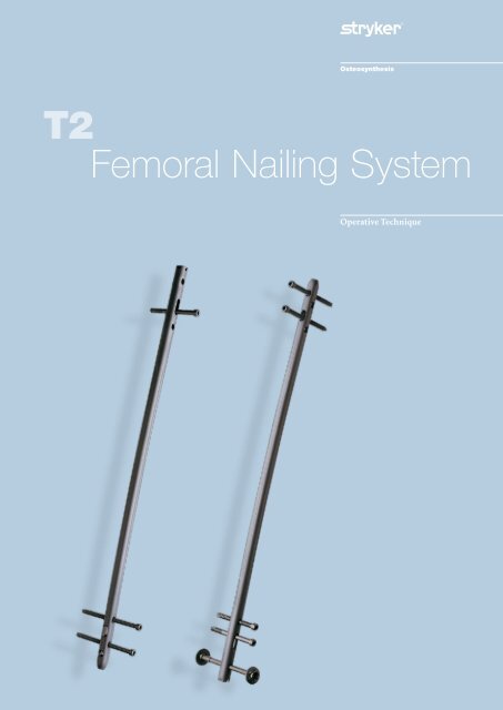
T2 Femoral Nailing System - Stryker
T2 Femoral Nailing System - Stryker
T2 Femoral Nailing System - Stryker

Create successful ePaper yourself
Turn your PDF publications into a flip-book with our unique Google optimized e-Paper software.
<strong>T2</strong><br />
<strong>Femoral</strong> <strong>Nailing</strong> <strong>System</strong><br />
Operative Technique
<strong>Femoral</strong> <strong>Nailing</strong> <strong>System</strong><br />
Contributing Surgeons<br />
Prof. Dr. med. Volker Bühren<br />
Chief of Surgical Services<br />
Medical Director of Murnau Trauma Center<br />
Murnau, Germany<br />
Joseph D. DiCicco III, D. O.<br />
Director Orthopaedic Trauma Service<br />
Good Samaritan Hospital<br />
Dayton, Ohio<br />
Associate Clinical Professor of Orthopeadic Surgery<br />
Ohio University and Wright State University<br />
USA<br />
Thomas G. DiPasquale, D. O.<br />
Associate Director, Orthopaedic Trauma Service<br />
Florida Orthopaedic Institute<br />
Tampa General Hospital<br />
Clinical Associate Professor of Orthopaedics<br />
Ohio University and Michigan State University<br />
Clinical Assistant Professor of Orthopaedics<br />
University of South Florida<br />
USA<br />
This publication sets forth detailed<br />
recommended procedures for using<br />
<strong>Stryker</strong> Osteosynthesis devices and<br />
instruments.<br />
It offers guidance that you should<br />
heed, but, as with any such technical<br />
guide, each surgeon must consider<br />
the particular needs of each patient<br />
and make appropriate adjustments<br />
when and as required.<br />
A workshop training is required prior<br />
to first surgery.<br />
See package insert (L22000007) for<br />
a complete list of potential adverse<br />
effects, contraindications, warnings<br />
and precautions. The surgeon must<br />
discuss all relevant risks, including<br />
the finite lifetime of the device, with<br />
the patient, when necessary.<br />
Warning:<br />
All bone screws referenced in this<br />
document here are not approved<br />
for screw attachment or fixation<br />
to the posterior elements<br />
(pedicles) of the cervical,<br />
thoracic or lumbar spine.<br />
2
Contents<br />
Page<br />
1. Introduction 4<br />
Implant Features 4<br />
Instrument Features 6<br />
References 6<br />
2. Indications and Contraindications 7<br />
Pre-operative Planning 7<br />
3. Additional Information 8<br />
Locking Options 8<br />
4. Operative Technique -Retrograde Technique 10<br />
Patient Positioning 10<br />
Incision 10<br />
Entry Point 11<br />
Unreamed Technique 12<br />
Reamed Technique 12<br />
Nail Selection 13<br />
Nail Insertion 14<br />
Guided Locking Mode (via Target Device) 16<br />
Static Locking Mode 17<br />
Freehand Proximal Locking 20<br />
End Cap Insertion 21<br />
Dynamic Locking Mode 22<br />
Apposition /Compression Locking Mode 22<br />
Advanced Locking Mode 24<br />
Nail Removal 25<br />
5. Operative Technique - Antegrade Technique 26<br />
Patient Positioning anf Fracture Reduction 26<br />
Incision 26<br />
Entry Point 27<br />
Unreamed Technique 27<br />
Reamed Technique 28<br />
Nail Selection 29<br />
Nail Insertion 30<br />
Guided Locking Mode (via Target Device) 31<br />
Static Locking Mode 32<br />
Freehand Distal Locking 33<br />
End Cap Insertion 34<br />
Dynamic Locking Mode 34<br />
Apposition /Compression Locking Mode 35<br />
Advanced Locking Mode 36<br />
Nail Removal 36<br />
Ordering Information – Implants 37<br />
Ordering Information – Instruments 40<br />
3
Introduction<br />
Over the past several decades antegrade<br />
femoral nailing has become<br />
the treatment of choice for most<br />
femoral shaft fractures. Retrograde<br />
femoral nailing has expanded the<br />
use of intramedullary nails (1, 2).<br />
Complicated multiple trauma injuries,<br />
associated pelvic and acetabular<br />
frac tures, ipsilateral femoral shaft<br />
fractures, supracondylar and intercondylar<br />
fractures, may be better<br />
managed by utilizing retrograde<br />
femoral nailing techniques<br />
(3, 4, 5, 6, 7).<br />
The <strong>T2</strong> <strong>Femoral</strong> <strong>Nailing</strong> <strong>System</strong><br />
is one of the first femoral nailing<br />
systems to offer an option for either<br />
an antegrade or a retrograde ap proach<br />
to repair fractures of the femur.<br />
One Implant, Two Approaches<br />
<strong>Stryker</strong> has created a next generation<br />
locking nail system, bringing together<br />
all the capabilities and benefits of<br />
separate antegrade and retrograde<br />
nailing systems to create a single,<br />
integrated surgical resource for<br />
fixation of long-bone fractures.<br />
Furthermore, the development of<br />
the <strong>T2</strong> <strong>Femoral</strong> <strong>Nailing</strong> <strong>System</strong> offers<br />
the competitive advantages of:<br />
• Not limiting the approach to<br />
a certain nailing technique<br />
• Accommodating reamed or<br />
unreamed procedures<br />
• Providing locking options for<br />
all types of fractures, plus the<br />
Advanced Locking Mode for<br />
increased rotational stability<br />
Through the development of a common,<br />
streamlined and intuitive<br />
surgical approach, both in principle<br />
and in detail, the <strong>T2</strong> <strong>Femoral</strong> <strong>Nailing</strong><br />
<strong>System</strong> offers significantly increased<br />
speed and functionality for the<br />
treatment of fractures as well as<br />
simplifying the training requirements<br />
for all personnel involved.<br />
Implant Features<br />
The <strong>T2</strong> <strong>Femoral</strong> <strong>Nailing</strong> <strong>System</strong> is<br />
the realization of superior biomechanical<br />
intramedullary stabilization<br />
using small caliber, strong, cannulated<br />
implants for internal fixation<br />
of long bones. According to the<br />
frac ture type, the system offers the<br />
option of different locking modes. In<br />
addition to static locking, a controlled<br />
dynamization with rotational<br />
stability is an option.<br />
In some indications, a controlled<br />
apposition/compression of bone<br />
fragments can be applied by introducing<br />
a Compression Screw from<br />
the top of the nail. To further<br />
in crease rotational stability, the nail<br />
can be locked statically after using<br />
the controlled dynamization and<br />
apposition/compression option.<br />
The Compression Screw is pushed<br />
against the Partially Threaded<br />
Locking Screw (Shaft Screw) that<br />
has been placed in the oblong hole,<br />
drawing either the distal or the<br />
proximal segment towards the<br />
fracture site. In stable fractures, this<br />
has the biomechanical advantage<br />
of creating active circumferential<br />
compression to the fracture site,<br />
transferring axial load to the bone,<br />
and reducing the function of the nail<br />
as a load bearing device (8).<br />
This ability to transfer load back to<br />
the bone can reduce the incidence<br />
of implant failure secondary to<br />
fatigue. Typical statically locked nails<br />
function as load bearing devices, and<br />
failure rates in excess of 20 % have<br />
been re ported (9).<br />
The beneficial effect of apposition/<br />
compression in treating long-bone<br />
fractures in cases involving transverse<br />
and short oblique fractures that are<br />
axially stable is well documented<br />
(10, 11).<br />
Anthropological (13) and forensic<br />
(14) literature reveals that differences<br />
in the anterior femoral curvature<br />
between racial and ethnic groups have<br />
long been recognized.<br />
Beside the <strong>T2</strong> <strong>Femoral</strong> nail with a 3m<br />
radius of curvature, <strong>Stryker</strong> offers<br />
also a 1.5m radius <strong>T2</strong> <strong>Femoral</strong> Nail<br />
to complete the product offering for<br />
those patients with a higher anterior<br />
femoral curvature.<br />
Common 5mm cortical screws*<br />
sim plify the surgical procedure<br />
and promote a minimally invasive<br />
approach. Fully Threaded Locking<br />
Screws are available for regular<br />
locking procedures. Partially<br />
Threaded Locking Screws (Shaft<br />
Screws) are designed if apposition/<br />
compression is applied. Special<br />
Condyle Screws with adjustable<br />
washers for improved fit are designed<br />
to fix fragments in the condyle area.<br />
They also allow controlled “lag effect“<br />
with intercondylar split type fractures.<br />
Compression Screws to close the<br />
fracture site and End Caps are<br />
available in various sizes to provide an<br />
improved fit for every indication.<br />
All implants of the <strong>T2</strong> <strong>Femoral</strong><br />
<strong>Nailing</strong> <strong>System</strong> are made of Type II<br />
anodized titanium alloy (Ti6AL4V)<br />
for enhanced biomechanical and<br />
biomedical performance.<br />
See the detailed chart on the next<br />
page for the design specifications and<br />
size offerings.<br />
* Special order 8mm <strong>T2</strong> <strong>Femoral</strong> Nails can<br />
only be locked with 4mm Fully Threaded<br />
screws at the non-driving end. As with all<br />
diameters of <strong>T2</strong> <strong>Femoral</strong> Nails, the screws<br />
for driving end locking are 5mm.<br />
4
Introduction<br />
Nails<br />
Diameter 9−15mm (special order 8mm)*<br />
Sizes 140−480mm<br />
Antegrade<br />
0mm<br />
15<br />
25<br />
Note:<br />
Screw length is measured from top<br />
of head to tip.<br />
35<br />
40<br />
32.5<br />
42.5<br />
50<br />
45mm<br />
5.0mm Partially Threaded Locking<br />
Screws (Shaft Screws)<br />
L = 25−120mm<br />
5.0mm Fully Threaded<br />
Locking Screws<br />
L = 25−120mm<br />
5.0mm Condyle Screws<br />
L = 40−120mm<br />
Condyle Nut<br />
Compression<br />
Screws<br />
Femur Advanced<br />
Compression<br />
Screw<br />
50<br />
Compression<br />
Range*<br />
Advanced<br />
Compression<br />
Screw<br />
45<br />
35<br />
60<br />
47.5<br />
32.5<br />
15<br />
25<br />
0mm<br />
Standard +5mm +10mm +15mm<br />
0mm<br />
Retrograde<br />
End Caps<br />
* 8mm nails (special order) require 4mm<br />
Fully Threaded Screws for Distal Locking<br />
* Compression Range<br />
Standard +5mm +10mm +15mm +20mm +25mm +30mm +35mm<br />
Total Length of Slot<br />
Less Screw Diameter (-)<br />
Maximum Movement of Screw<br />
15mm<br />
5mm<br />
10mm<br />
5
Introduction<br />
Instrument<br />
Features<br />
The major advantage of the instrument<br />
system is a breakthrough in the<br />
integration of the instrument platform<br />
which can be used not only for<br />
the complete <strong>T2</strong> <strong>Nailing</strong> <strong>System</strong>, but<br />
will be the platform for future <strong>Stryker</strong><br />
nailing systems, thereby reducing<br />
complexity and inventory.<br />
The instrument platform offers<br />
ad vanced precision and usability, and<br />
features ergonomically styled targeting<br />
devices.<br />
In addition to the advanced precision<br />
and usability, the instruments are both<br />
number and symbol coded to indicate<br />
their usage during the surgical<br />
procedure.<br />
Number coding indicates the step<br />
during the procedure in which the<br />
instrument is used. This number code<br />
system is marked on the trays to easily<br />
identify the correct instrument.<br />
Step<br />
Number<br />
Opening 1<br />
Reduction 2<br />
Nail Introduction 3<br />
Guided Locking 4<br />
Freehand Locking 5<br />
Symbol coding on the instruments<br />
indicates the type of procedure, and<br />
must not be mixed.<br />
Symbol<br />
Drills<br />
Square =<br />
Long instruments<br />
Triangular = Short instruments<br />
Drills feature color coded rings :<br />
4.2mm = Green<br />
For 5.0mm Fully Threaded Locking<br />
Screws and for the second cortex<br />
when using 5.0mm Partially Threaded<br />
Locking Screws (Shaft Screws).<br />
5.0mm = Black<br />
For the first cortex when using 5.0mm<br />
Partially Threaded Locking Screws<br />
(Shaft Screws) and for both corticies<br />
when using Condyle Screws.<br />
References<br />
1. Janzing HMJ et al.: The Retrograde<br />
Intramedullary Nail: Prospective<br />
Experience in Patients Older than<br />
Sixty-five Years. Journal of Orthopaedic<br />
Trauma 12 (5) 330-333, 1998<br />
2. Koval KJ et al.: Distal <strong>Femoral</strong> Nonunion:<br />
Treatment with a Retrograde<br />
Inserted Locked Intramedullary Nail,<br />
Journal of Orthopaedic Trauma, Vol. 9<br />
N°4, pp. 285-291, 1995<br />
3. Herscovici D Jr. and Whiteman KW:<br />
Retrograde <strong>Nailing</strong> of the Femur Using<br />
an Intercondylar Approach. Clinical<br />
Orthopaedics and related Research,<br />
332, 98-104, 1996<br />
4. Roy Sanders, Kenneth J. Koval et al.:<br />
Retrograde Reamed <strong>Femoral</strong> <strong>Nailing</strong>.<br />
Journal of Orthopaedic Trauma 1993;<br />
Vol. 7, No. 4: 293-302<br />
5. Ostrum F. D., et al., A Prospective<br />
Comparison of Antegrade and<br />
Retrograde Intramedullary <strong>Nailing</strong>,<br />
Friday, October 9, 1998 Session V, 11:31<br />
a. m. OTA Vancouver<br />
6. Ostrum F. D., Joseph DiCicco,<br />
Retrograde In tramedullary <strong>Nailing</strong> of<br />
<strong>Femoral</strong> Diaphyseal Fractures, Journal<br />
of orthopaedic Trauma, Vol. 12,<br />
N° 7, pp. 464-468, 1998<br />
7. Lucas SE et al.: Intramedullary<br />
Supracondylar <strong>Nailing</strong> of <strong>Femoral</strong><br />
Fractures. A Preliminary Report of<br />
the GSH Supracondylar Nail. Clinical<br />
Orthopaedics and Related Research<br />
296 200-206, 1993<br />
8. T. E. Richardson, M. Voor,<br />
D. Seligson, Fracture Site Compression<br />
and Motion with Three Types of<br />
Intramedullary Fixation of the Femur,<br />
Osteosynthese International (1998), 6:<br />
261-264<br />
6<br />
9. Hutson et al., Mechanical Failures<br />
of Intramedullary Tibial Nails Applied<br />
without Reaming, Clin. Orthop. (1995),<br />
315: 129-137<br />
10. M.E. Muller, et al., Manual of<br />
Internal Fixation, Springer-Verlag,<br />
Berlin, 1991<br />
11. O. Gonschorek, G. O. Hofmann,<br />
V. Bühren, Interlocking Compression<br />
<strong>Nailing</strong>: a Report on 402 Applications.<br />
Arch. Orthop. Trauma Surg (1998), 117:<br />
430-437.<br />
12. Mehdi Mousavi, et al., Pressure<br />
Changes During Reaming with<br />
Different Parameters and Reamer<br />
Designs, Clinical Orthopaedics<br />
and Related Research, Number 373,<br />
pp. 295-303, 2000.<br />
13. Gilbert BM. Anterior femoral curvature:<br />
its propabable basis and utility<br />
as a criterion of a racial assessment.<br />
Am J Phys Anthropol. 1976;45:601-<br />
604.5.<br />
14. Ballard ME, Trudell MB. Anterior<br />
femoral curvature revisited: race<br />
assessment from the femur. J Forensic<br />
Sci. 1999;44:700-707.
Indications and Contraindications<br />
The <strong>T2</strong> <strong>Femoral</strong><br />
Nail is indicated<br />
for:<br />
• Open and closed shaft fractures<br />
• Ipsilateral shaft fractures<br />
• Segmental fractures<br />
• Supracondylar fractures including<br />
those with intra-articular<br />
extension<br />
• Comminuted fractures with or<br />
without bone loss<br />
• Fractures distal to a hip prosthesis<br />
• Fractures proximal to a total knee<br />
arthroplasty<br />
• Pathologic and impending<br />
pathologic fractures<br />
• Tumor resections<br />
• Non-unions<br />
• Pseudarthrosis<br />
• Mal-unions<br />
• Corrective osteotomies<br />
tures or physiological performance.<br />
• Any mental or neuromuscular<br />
disorder which would create an<br />
unacceptable risk of fixation<br />
failure or complications in<br />
postoperative care.<br />
• Other medical or surgical<br />
conditions which would preclude<br />
the potential benefit of surgery.<br />
Pre-operative<br />
Planning<br />
An X-Ray Template 1806-0005 is<br />
available for pre-operative planning.<br />
Thorough evaluation of pre-operative<br />
radiographs of the affected extrem ity<br />
is critical. Careful radiographic ex -<br />
am ination of the trochanteric region<br />
and intercondylar regions can prevent<br />
intra-operative complications.<br />
Antegrade<br />
Retrograde<br />
Relative<br />
Contraindications:<br />
The proper nail length when inserted<br />
antegrade should extend from the<br />
Tip of the Greater Trochanter to the<br />
Epiphyseal Scar.<br />
The physician’s education, training<br />
and professional judgement must<br />
be relied upon to choose the most<br />
appropriate device and treatment.<br />
Conditions presenting an increased<br />
risk of failure include:<br />
• Any active or suspected latent<br />
infection or marked local<br />
inflammation in or about the<br />
affected area.<br />
• Compromised vascularity that<br />
would inhibit adequate blood<br />
supply to the fracture or the<br />
operative site.<br />
• Bone stock compromised by<br />
disease, infection or prior<br />
implantation that can not provide<br />
adequate support and/or fixation<br />
of the devices.<br />
• Material sensitivity, documented<br />
or suspected.<br />
• Obesity. An overweight or obese<br />
patient can produce loads on the<br />
implant that can lead to failure<br />
of the fixation of the device or to<br />
failure of the device itself.<br />
• Patients having inadequate tissue<br />
coverage over the operative site.<br />
• Implant utilization that would<br />
interfere with anatomical struc-<br />
The retrograde nail length is determined<br />
by measuring the distance<br />
between a point 5mm–15mm proximal<br />
to the Intercondylar Notch to<br />
a point at/or proximal to the Lesser<br />
Trochanter.<br />
In either approach this allows the<br />
surgeon to consider the apposition/<br />
compression feature of the <strong>T2</strong> <strong>Femoral</strong><br />
Nail, knowing that up to 10mm<br />
of active apposition/compression is<br />
possible, prior to determining the final<br />
length of the implant. If apposition/<br />
compression is planned, the nail<br />
should be 10mm to 15mm shorter.<br />
Note:<br />
Check with local representative<br />
regarding availability of nail sizes.<br />
7
Additional Information<br />
Locking Options<br />
Antegrade<br />
Static Mode<br />
Retrograde<br />
8
Additional Information<br />
Dynamic Mode Apposition / Compression Mode Advanced Locking Mode<br />
9
Operative Technique - Retrograde Technique<br />
Incision<br />
5mm<br />
Patient Positioning<br />
Retrograde nail insertion is performed<br />
with the patient supine on a<br />
radiolucent table. The affected lower<br />
extremity and hip region are freely<br />
draped, and the knee is placed over<br />
a sterile bolster. This will allow for<br />
30-45 degrees of knee flexion. Manual<br />
traction through a flexed knee or a<br />
distraction device may be used to<br />
facilitate reduction for most acute<br />
femoral shaft fractures.<br />
10<br />
A 3cm midline skin incision is made<br />
extending from the inferior pole of the<br />
Patella to the Tibial Tubercle, followed<br />
by a medial parapatellar capsular<br />
in ci sion. This should be sufficient to<br />
expose the Intercondylar Notch for<br />
retrograde nail insertion. Occasionally,<br />
a larger incision may be needed, especially<br />
if the fracture has intra-articular<br />
extension and fixation of the condyles<br />
is necessary.<br />
Distal femoral fractures are often<br />
complicated by intra-articular fracture<br />
line extension. These fractures should<br />
be anatomically reduced and secured<br />
with the aid of titanium Asnis III<br />
6.5mm/8.0mm Large Cannulated<br />
Screws in the anterior and posterior<br />
aspect of the femoral condyles. This<br />
will allow for adequate space when<br />
inserting the nail retrograde. Cannulated<br />
Screws are advantageous, al lowing<br />
the surgeon to use intra-operative<br />
radiographs to check Guide Wire<br />
place ment prior to screw insertion. An<br />
alternative is to reduce and maintain<br />
reduction of the femoral condyles with<br />
a pointed reduction forceps during the<br />
insertion of the retrograde nail and<br />
place cannulated screws after the nail<br />
is inserted.
Operative Technique - Retrograde Technique<br />
Entry Point<br />
The 3 × 285mm K-Wire (1806-0050S)*<br />
can easily be fixed to the Guide Wire<br />
Handle (1806-0095 and 1806-0096)<br />
(Fig. 1). With the condyles secured,<br />
the entry point for retrograde nail<br />
in ser tion is made by centering the<br />
3 × 285mm K-Wire through the<br />
Retrograde Protection Sleeve<br />
(703165) and positioning within<br />
the Intercondylar Notch anterior<br />
to Blumensaat‘s line on the M/L<br />
radiograph using the Slotted Hammer<br />
(1806-0170) (Fig. 2).<br />
Fig. 1<br />
This point is found by palpating a<br />
distinct ridge just anterior to the<br />
Posterior Cruciate Ligament (Fig. 2).<br />
The K-Wire is advanced manually or<br />
with the Slotted Hammer ap prox i-<br />
mately 10cm confirming its place ment<br />
within the center of the distal femur<br />
on an A/P and Lateral radiograph.<br />
The Retrograde Protection Sleeve<br />
Fig. 2<br />
is contoured to fit the profile of the<br />
Intercondylar Notch. It is designed<br />
to help reduce the potential for<br />
damage during reaming, and also<br />
provide an avenue for the reamer<br />
debris to exit the knee joint (Fig. 3).<br />
When the inner Retrograde K-Wire<br />
Guide is removed, the Ø12mm Rigid<br />
Reamer (1806-2012) is inserted over<br />
the 3 × 285mm K-Wire and through<br />
the Retrograde Protection Sleeve.<br />
The distal most 8cm of the femur is<br />
reamed (Fig. 4).<br />
The Ø12mm Rigid Reamer is used for<br />
nails 9mm−11mm in diameter. Larger<br />
nail diameters may be reamed with a<br />
flexible reamer 1mm larger than the<br />
nail.<br />
Fig. 3<br />
Caution:<br />
Prior to advancing the K-Wire<br />
within the distal femur, check<br />
the correct guidance through the<br />
Ø12mm Rigid Reamer. Do not use<br />
bent K-Wires.<br />
Note:<br />
During opening the entry portal<br />
with the Awl, dense cortex may<br />
block the tip of the Awl. An<br />
Awl Plug (1806-0032) can be<br />
inserted through the Awl to avoid<br />
penetration of bone debris into<br />
the cannulation of the Awl shaft.<br />
Fig. 4<br />
* Outside of the U. S., product with an “S” may be<br />
ordered non-sterile without the “S” at the end of<br />
the corresponding Cat. Number.<br />
11
Operative Technique - Retrograde Technique<br />
Unreamed<br />
Technique<br />
If an unreamed technique is pre ferred,<br />
the 3 × 1000mm Ball Tip Guide Wire<br />
(1806-0085S) is passed through the<br />
fracture site using the Guide Wire<br />
Handle. The Universal Rod (1806-0110)<br />
with Reduction Spoon (1806-0125)<br />
may be used as a fracture reduction<br />
tool to facilitate Guide Wire insertion<br />
(Fig. 5). Internal rotation during<br />
insertion will aid in passing the Guide<br />
Wire down the femoral shaft. The<br />
Guide Wire is advanced until the<br />
tip rests at/or just above the Lesser<br />
Trochanter. The Guide Wire should<br />
lie in the center of the metaphysis in<br />
the A/P and M/L views to avoid offset<br />
positioning of the nail. The Guide<br />
Wire Handle is removed, leaving the<br />
Guide Wire in place.<br />
Fig. 5<br />
Reamed<br />
Technique<br />
For reamed techniques, the<br />
3 × 1000mm Ball Tip Guide Wire is<br />
inserted through the fracture site<br />
and does not require a Guide Wire<br />
exchange. The Universal Rod with<br />
Reduction Spoon may be used as a<br />
fracture reduction tool to facilitate<br />
Guide Wire insertion through the<br />
fracture site (see Fig. 5).<br />
Note:<br />
The Ball Tip at the end of the<br />
Guide Wire will stop the reamer<br />
head.<br />
Reaming (Fig. 6) is commenced in<br />
0.5mm increments until cortical<br />
contact is appreciated. Final reaming<br />
should be 1mm larger than the<br />
diameter of the nail to be used.<br />
Caution:<br />
The diameter of the driving end<br />
of the 9mm–11mm (and special<br />
oder 8mm nails) diameter nails is<br />
11.5mm. Additional metaphyseal<br />
reaming may be required to<br />
facilitate nail insertion. Nail<br />
sizes 12–15mm have a constant<br />
diameter.<br />
Thoroughly irrigate the knee joint<br />
to remove any debris.<br />
Note:<br />
8mm <strong>Femoral</strong> Nails cannot be<br />
inserted over the 3×1000mm Ball<br />
Tip Guide Wire (1806-0085S).<br />
The Ball Tip Guide wire must<br />
be exchanged for the 3×800mm<br />
Smooth Tip Guide Wire (1806-<br />
0090S) prior to nail insertion.<br />
Use the Teflon Tube (1806-0073S)<br />
for the guide wire exchange.<br />
Fig. 6<br />
Bixcut Reamer *<br />
The complete range of Bixcut reamers<br />
is available with either modular or<br />
fixed heads.<br />
The optimized cutting flute geometry<br />
is designed to largely reduce<br />
intramedul-lary pressure and temperature.<br />
This is achieved by the<br />
forward and side cutting face combination<br />
of the reamer blades. The<br />
large clearance rate resulting from<br />
the reduced number of reamer blades,<br />
coupled with the reduced length<br />
of the reamer head, relieves the<br />
in tramedullary pressure and provides<br />
efficient removal of reamed material.<br />
See pages 42–43 for additional Bixcut<br />
Reamer system details.<br />
12
Operative Technique - Retrograde Technique<br />
Nail Selection<br />
Diameter<br />
The diameter of the selected nail<br />
should be 1mm smaller than that of<br />
the last reamer used. Alternatively,<br />
the nail diameter may be determined<br />
using the Femur X-Ray Ruler (1806-<br />
0015) (Fig. 7.1 and 7.2).<br />
3 1 2 1<br />
Length Scale<br />
Diameter Scale<br />
Fig. 7.1<br />
Fig. 7.1 Hole Positions (nondriving<br />
end) Antegrade or Retrograde*<br />
1. Static Locking – both M/L holes<br />
2. Oblong hole – depending on<br />
Antegrade or Retrograde;<br />
static or dynamic modes – A/P<br />
3. Static Locking – A/P<br />
Fig. 7.2 Hole Positions (driving end)<br />
Antegrade or Retrograde*<br />
1. Static Locking – both M/L holes<br />
2. Oblong hole – depending on<br />
Antegrade or Retrograde; static,<br />
dynamic, apposition/compres sion,<br />
advanced locking modes – M/L<br />
Length<br />
330 mm<br />
Hole Positions<br />
(driving end)<br />
1 2 1<br />
Length<br />
Static and<br />
Calibration Dynamic Slot Fig. 7.2<br />
Locking Options<br />
Length<br />
Nail length may be determined by<br />
measuring the remaining length of the<br />
Guide Wire. The Guide Wire Ruler<br />
(1806-0020) may be used by placing it<br />
on the Guide Wire reading the correct<br />
nail length at the end of the Guide<br />
Wire on the Guide Wire Ruler<br />
(Fig. 8 and Fig. 9).<br />
Alternatively, the X-Ray Ruler (1806-<br />
0015) may be used to determine nail<br />
diameter and length (Fig. 7.1, 7.2).<br />
Additionally, the X-Ray Ruler can<br />
be used as a guide for locking screw<br />
positions.<br />
End of Guide Wire Ruler<br />
equals Measurement Reference<br />
Fig. 8<br />
Note:<br />
X-Ray Ruler and Guide Wire<br />
Ruler can be used for nail length<br />
determination beginning from<br />
240mm. Shorter nail length can<br />
be determined via the template.<br />
Caution:<br />
If the fracture is suitable for ap position/compression,<br />
the implant<br />
selected should be 10–15mm<br />
shorter than measured, to help<br />
avoid migration of the nail<br />
beyond the insertion site.<br />
* see pages 8–9 for detailed illustrations of<br />
Antegrade and Retrograde Locking Options.<br />
Fig. 9<br />
13
Operative Technique - Retrograde Technique<br />
Nail Insertion<br />
The selected nail is assembled onto the<br />
<strong>Femoral</strong> Target Device (1806-1005)<br />
with the <strong>Femoral</strong> Nail Holding Screw<br />
(1806-0165) (Fig. 10). Tighten the Nail<br />
Holding Screw with the Universal<br />
Joint Socket Wrench (1806-0400)<br />
securely so that it does not loosen<br />
during nail insertion.<br />
Caution:<br />
Prior to nail insertion please<br />
check correct alignment by<br />
inserting a drill bit through the<br />
assembled Tissue Protection- and<br />
Drill Sleeve placed in the required<br />
holes of the targeting device.<br />
Upon completion of reaming, the<br />
appropriate size nail is ready for<br />
in ser tion. Unique to the <strong>T2</strong> <strong>Femoral</strong><br />
Nail, the 3 × 1000mm Ball Tip Guide<br />
Wire does not need to be exchanged.<br />
The Strike Plate (1806-0150) may be<br />
threaded into the hole next to the<br />
Nail Holding Screw and the nail is<br />
advanced through the entry point past<br />
the fracture site to the appropriate<br />
level.<br />
Fixation<br />
Screw<br />
Targeting<br />
Arm<br />
Nail Holding Screw<br />
Strike Plate<br />
Nail<br />
Handle<br />
Additionally, the 3 × 285mm K-Wire<br />
may be inserted through the Targeting<br />
Device which identifies the junction<br />
of the nail and insertion post which<br />
helps determine nail depth through<br />
a mini incision using X-Ray (see Fig.<br />
10.1).<br />
K-Wire Hole<br />
Insertion of the 3 × 285mm K-Wire<br />
into the lateral cortex may also help<br />
to lock the targeting device to the<br />
distal femur and prevent rotation of<br />
the nail in cases where the Apposition/<br />
Compression Locking Mode is<br />
utilized.<br />
Fig. 10<br />
Caution:<br />
Curvature of the nail must match<br />
the curvature of the femur.<br />
Fig. 10.1<br />
14
Operative Technique - Retrograde Technique<br />
The Slotted Hammer can be used on<br />
the Insertion Wrench that is placed<br />
onto the Nail Holding Screw to insert<br />
the nail over a Guide Wire (Fig. 11).<br />
A chamfer is located on the driving<br />
end of the nail to denote the end<br />
under X-Ray. Three circumferential<br />
grooves are located on the insertion<br />
post at 2mm, 10mm, and 15mm from<br />
the driving end of the nail. Depth of<br />
insertion may be visualized with the<br />
aid of fluoroscopy.<br />
Repositioning should be carried<br />
out either by hand or by using the<br />
Strike Plate attached to the Target<br />
Device. The Universal Rod and Slotted<br />
Hammer may then be attached to the<br />
Strike Plate to carefully and smoothly<br />
extract the assembly (Fig. 12). DO<br />
NOT hit on the Target Device.<br />
Fig. 11<br />
When locking the retrograde nail<br />
in the Static Mode, the nail is<br />
countersunk a minimum of 5mm<br />
to the chondral surface. When the<br />
implant is inserted in the Dynamic<br />
Mode, without active apposition/<br />
compression, the recommended<br />
insertion depth is 10mm. When<br />
the implant is inserted with active<br />
apposition/compression or in<br />
the Advanced Locking Mode, the<br />
recommended depth of insertion is<br />
15mm (Fig. 13).<br />
Note:<br />
Remove the Guide Wire prior<br />
to drilling and inserting the<br />
Locking Screws.<br />
Fig. 12<br />
5mm<br />
2mm<br />
10mm<br />
15mm<br />
Static<br />
Dynamic<br />
Apposition/Compression<br />
Fig. 13<br />
15
Operative Technique - Retrograde Technique<br />
Guided Locking Mode (via Target Device)<br />
Before locking the nail distally, the<br />
Nail Holding Screw must be firmly<br />
tightened using the Universal Joint<br />
Socket Wrench to ensure that the nail<br />
is correctly aligned with the Target<br />
Device.<br />
The Target Device is designed to<br />
provide four options for distal<br />
locking (Fig. 14.1–14.3).<br />
3<br />
2<br />
1<br />
In Static Locking Mode, all three<br />
indicated holes may be used (Fig.<br />
14.1).<br />
Fig. 14.1<br />
1. Static<br />
2. Static<br />
3. Static<br />
In controlled Dynamic Mode, and/or<br />
controlled Apposition/Compression<br />
Mode, the dynamic hole is required.<br />
This hole is also used for compression<br />
(Fig. 14.2).<br />
4<br />
4. Dynamic<br />
In Advanced Locking Mode, the<br />
dynamic hole is required. After<br />
utilizing compression with the<br />
Advanced Compression Screw, either<br />
or both static holes are used. (Fig.<br />
14.3).<br />
4. Dynamic<br />
1. Static<br />
3. Static<br />
The Long Tissue Protection<br />
Sleeve (1806-0185) together<br />
with the Long Drill Sleeve<br />
(1806-0215) and the Long Trocar<br />
(1806-0315) is inserted into the Target<br />
Device by pressing the safety clip (Fig.<br />
15). The mechanism will keep the<br />
sleeve in place and prevent it from<br />
falling out.<br />
It will also prevent the sleeve from<br />
sliding during screw measurement. To<br />
release the Tissue Protection Sleeve,<br />
the safety clip must be pressed again.<br />
3<br />
4<br />
1<br />
Fig. 14.2<br />
Fig. 14.3<br />
released<br />
locked<br />
Fig. 15<br />
16
Operative Technique - Retrograde Technique<br />
Static Locking<br />
Mode<br />
When treating supracondylar frac tures,<br />
three screws should be used whenever<br />
possible. The screw placed within the<br />
oblong hole should be in the static<br />
position. Always start with the most<br />
proximal screw.<br />
If secondary dynamization is planned,<br />
it is recommended to dynamize at<br />
the proximal portion of the nail.<br />
This is achieved by putting a Fully<br />
Threaded Locking Screw at the proximal<br />
location of the A/P oblong hole<br />
at the top of the nail. This allows<br />
dynamization of the fracture in case<br />
of delayed union after removal of the<br />
most proximal screw.<br />
Fig. 16<br />
The Long Tissue Protection Sleeve<br />
together with the Long Drill Sleeve<br />
and Long Trocar, are positioned<br />
through the static locking hole on the<br />
Target Device. A small skin incision<br />
is made, and the assembly is pushed<br />
through until it is in contact with the<br />
lateral cortex of the femur (Fig. 16).<br />
The Trocar is removed, with the<br />
Tissue Protection Sleeve and the Drill<br />
Sleeve remaining in position.<br />
To ensure accurate drilling and easy<br />
determination of screw length, use the<br />
center tipped, Ø4.2 × 340 calibrated<br />
Drill (1806-4260S). The centered Drill<br />
is forwarded through the Drill Sleeve<br />
and pushed onto the cortex.<br />
Fig. 17<br />
50mm<br />
17
Operative Technique - Retrograde Technique<br />
After drilling both cortices, the screw<br />
length may be read directly off of the<br />
calibrated Drill at the end of the Drill<br />
Sleeve. If measurement with the Screw<br />
Gauge, Long is preferred, first remove<br />
the Drill Sleeve, Long and read the<br />
screw length directly at the end of the<br />
Tissue Protection Sleeve, Long (Fig. 17<br />
and Fig. 18).<br />
Caution:<br />
Make sure the Tissue Protection<br />
Sleeve/Drill Sleeve Assembly is<br />
seated on bone prior to selecting<br />
final screw length.<br />
50mm<br />
Note:<br />
The position of the end of the<br />
Drill as it relates to the far cortex<br />
is equal to where the end of the<br />
screw will be. Therefore, if the<br />
end of the Drill is 3mm beyond<br />
the far cortex, the end of the<br />
screw will also be 3mm beyond.<br />
The Screw Gauge, Long is calibrated<br />
so that with the bend at the end pulled<br />
back flush with the far cortex, the<br />
screw tip will end 3mm beyond the far<br />
cortex (Fig. 18).<br />
When the Drill Sleeve is removed, the<br />
correct Locking Screw is inserted<br />
through the Tissue Protection Sleeve<br />
using the Long Screwdriver Shaft<br />
(1806-0227) with Teardrop Handle<br />
(702429). The screw is advanced<br />
through both cortices.<br />
The screw is near its’ proper seating<br />
position when the groove around the<br />
shaft of the screwdriver is approach ing<br />
the end of the Tissue Protection Sleeve<br />
(Fig. 19).<br />
Repeat the locking procedure for<br />
the other statically positioned Cross<br />
Locking Screws.<br />
Caution:<br />
The coupling of Elastosil handles<br />
contains a mechanism with<br />
one or multiple ball bearings.<br />
In case of applied axial stress<br />
on the Elastosil handle, those<br />
components are pressed into the<br />
surrounding cylinder resulting in<br />
a complete blockage of the device<br />
and possible bending.<br />
To avoid intra-operative<br />
complications and secure longterm<br />
functionality, we mandate<br />
that Elastosil handles be used only<br />
for their intended use. DO NOT<br />
HIT on them.<br />
Fig. 18<br />
Fig. 19<br />
Alternatively, the 3.5mm Hex Self-<br />
Holding Screwdriver Long (1806-0233)<br />
can be used for the screw insertion.<br />
18
Operative Technique - Retrograde Technique<br />
Condyle Screw Locking<br />
If a Condyle Screw is to be inserted,<br />
both cortices are drilled with the<br />
Ø5 × 340mm Drill (1806-5020S)<br />
(Fig. 20). After drilling both cortices,<br />
the screw length may be read directly<br />
off of the calibrated Drill at the end<br />
of the Drill Sleeve. The Condyle<br />
Screw K-Wire (0152-0218S) is<br />
inserted from the lateral side through<br />
the Tissue Protection Sleeve to the<br />
medial side. At the medial point of<br />
the perforation a skin incision is<br />
made for the Condyle Screw.<br />
Fig. 20<br />
From the medial side, the Condyle<br />
Screw is now brought forward over<br />
the Condyle Screw K-Wire and<br />
inserted using the Condyle Screw<br />
Screwdriver (1806-0255).<br />
To insert the Condyle Nut, the Tissue<br />
Protection Sleeve and the Drill Sleeve<br />
are removed, and the K-Wire is<br />
withdrawn to the medial side. This<br />
allows for the nut to be positioned<br />
between the Target Device and<br />
the level of the skin and onto the<br />
Condyle Screw K-Wire (Fig. 21).<br />
Alternatively, if the patient anatomy<br />
allows, the Condyle Screw may be<br />
introduced from Lateral to Medial in<br />
a similar manner as described above<br />
(Fig. 21a).<br />
Using both Condyle Screw Screwdrivers,<br />
the Condyle Nut and the<br />
Condyle Screw are tightened. Once<br />
tightened, the K-Wire is removed.<br />
The adjustable screw washer of the<br />
Condyle Screw and the Condyle<br />
Nut adapt to the surface of the bone<br />
eliminating the need to countersink<br />
both.<br />
The geometry of the implant allows<br />
three Condyle Screws to be used.<br />
At least two of the three distal<br />
holes should be engaged with either<br />
Locking Screws and/or Condyle<br />
Screws (Fig. 22). Always lock the<br />
most proximal hole.<br />
Condyle Screwintroduced<br />
M-L<br />
Condyle Screwintroduced<br />
L-M<br />
Fig. 21<br />
Fig. 21a<br />
Caution:<br />
If necessary, contour the bone<br />
geometry to optimize the<br />
seating of the washer. Fig. 22<br />
19
Operative Technique - Retrograde Technique<br />
Freehand<br />
Proximal Locking<br />
The freehand technique is used to<br />
insert Locking Screws into both the<br />
A/P oblong hole and A/P round hole<br />
in the nail. In Static, Apposition/<br />
Compression and Advanced Locking<br />
Mode, the Locking Screw placed in<br />
the oblong hole should be positioned<br />
in the distal position. Rotational<br />
alignment must be checked prior to<br />
locking the nail statically.<br />
Caution:<br />
Only one Locking Screw is<br />
inserted in the Dynamic Locking<br />
Mode. The Locking Screw is<br />
placed in the proximal position<br />
of the A/P oblong hole in order<br />
to optimize dynamization at the<br />
proximal end of the nail.<br />
The M/L holes may also be used<br />
alternatively or in addition to A/P<br />
Locking Screws by adjusting the<br />
C-Arm and leg position to locate the<br />
holes.<br />
Green Ring<br />
Fig. 23<br />
Fig. 24<br />
Multiple locking techniques and<br />
radiolucent drill devices are available<br />
for freehand locking. The critical step<br />
with any freehand locking technique,<br />
proximal or distal, is to visualize<br />
a perfectly round locking hole, or<br />
perfectly oblong locking hole with the<br />
C-Arm.<br />
The center-tipped Ø4.2 × 230 Drill<br />
(1806-4290S) is held at an oblique<br />
angle to the center of the locking<br />
hole (Fig. 23 and 24). Upon X-Ray<br />
verification, the Drill is placed<br />
perpendicular to the nail and drilled<br />
through the anterior and posterior<br />
cortex. Confirm that the Drill passes<br />
through the hole in the nail in both<br />
the A/P and M/L planes by X-Ray.<br />
Alternatively, the Screw Gauge can be<br />
to determine the screw length.<br />
After drilling both cortices the screw<br />
length may be read directly off of the<br />
calibrated Screw Scale, Long (1806-<br />
0365) at the green ring on the centertipped<br />
Drill (Fig. 25).<br />
As with proximal locking (Fig. 17,<br />
40mm<br />
p. 18), the position of the end of the<br />
drill is equal to the end of the screw<br />
as they relate to the far cortex.<br />
Routine Locking Screw insertion is<br />
employed with the assembled Long<br />
Screwdriver Shaft and the Teardrop<br />
Handle (Fig. 26).<br />
Caution:<br />
Special order 8mm <strong>T2</strong> <strong>Femoral</strong><br />
Nails can only be locked with 4mm<br />
Fully Threaded screws at the nondriving<br />
end. Use the Ø3.5 × 180 Drill<br />
Fig. 25<br />
Fig. 26<br />
(1806-3570S) for freehand locking.<br />
Alternatively, the 3.5mm Hex Self-<br />
Holding Screwdriver Extra-short<br />
(1806-0203) can be used for the screw<br />
insertion.<br />
20
Operative Technique - Retrograde Technique<br />
End Cap Insertion<br />
After removal of the Target Device, an<br />
End Cap is used. Eight different sizes<br />
of End Caps* are available to adjust<br />
nail length and to reduce the potential<br />
for bony ingrowth into the proximal<br />
thread of the nail (Fig. 27).<br />
Standard +5mm +10mm +15mm +20mm +25mm +30mm +35mm<br />
Fig. 27<br />
Note:<br />
All End Caps are designed to<br />
tighten down onto the locking<br />
screw at the working end of the<br />
nail. This will help prevent the<br />
nail from M/L sliding.<br />
The End Cap is inserted with the<br />
Long Screwdriver Shaft and Teardrop<br />
Handle after intra-operative radiographs<br />
show satisfactory reduction<br />
and hardware implantation (Fig. 28).<br />
Fully seat the End Cap to minimize<br />
the potential for loosening.<br />
Caution:<br />
Final verification of implants<br />
should be confirmed by X-Ray at<br />
this time.<br />
Fig. 28<br />
Thoroughly irrigate the wound to<br />
prevent debris from remaining within<br />
the knee joint. Close the wound using<br />
standard technique.<br />
Fig. 28a<br />
Alternatively, the 3.5mm Hex Self-<br />
Holding Screwdriver Long (1806-<br />
0233) can be used for the End Cap<br />
insertion.<br />
* Optional 8mm diameter End Caps are<br />
available in +5, +10 and +15mm length to<br />
facilitate insertion through the Nail Adapter<br />
(Fig. 28a & 28b).<br />
21<br />
Fig. 28b
Operative Technique - Retrograde Technique<br />
Dynamic Locking Mode<br />
When the fracture profile permits,<br />
controlled dynamic locking may be<br />
utilized for transverse or axially stable<br />
fractures. While dynamic locking can<br />
be performed at either end of the nail,<br />
routine retrograde dynamic locking<br />
should utilize the oblong hole at the<br />
proximal end of the nail. The potential<br />
for nail migration into the joint is<br />
thereby reduced.<br />
Retrograde dynamization is<br />
performed by statically locking the<br />
nail distally via the Target Device.<br />
The freehand Locking Screw is then<br />
placed in the dynamic position of the<br />
oblong hole. This allows the nail to<br />
move and the fracture to settle while<br />
torsional stability is maintained<br />
(Fig. 29).<br />
Fig. 29<br />
Apposition/Compression Locking Mode<br />
In transverse or axially stable<br />
fracture patterns, active apposition/<br />
compression increases fracture<br />
stability, may enhance fracture<br />
healing, and allow for early weight<br />
bearing. The <strong>T2</strong> <strong>Femoral</strong> Nail<br />
provides the option to treat a femur<br />
fracture with active mechanical<br />
apposition/compression prior to<br />
leaving the operating room.<br />
Caution:<br />
Proximal freehand static<br />
locking with at least two Fully<br />
Threaded Locking Screws must<br />
be performed prior to applying<br />
active, controlled apposition/<br />
compression to the fracture site.<br />
If active apposition/compression is<br />
required, a Partially Threaded Locking<br />
Screw (Shaft Screw) is inserted via the<br />
Target Device in the dynamic position<br />
of the oblong hole. This will allow<br />
for a maximum of 10mm of active,<br />
controlled apposition/compression. In<br />
order to insert the Shaft Screw, drill<br />
both cortices with the Ø4.2 × 340 Drill<br />
(1806-4260S). Next, drill the near<br />
cortex, ONLY, with the Ø5 × 230mm<br />
Drill (1806-5000S).<br />
After the opposite cortex is drilled<br />
with the Ø4.2 × 340mm Drill, the<br />
correct screw length can be read<br />
directly off of the calibrated Drill at<br />
the end of the Drill Sleeve.<br />
The 3.5mm Hex Self-Holding<br />
Screwdriver Long (1806-0233) can be<br />
use for screw insertion.<br />
22<br />
It may be easier to insert the Advanced<br />
Compression Screw prior to fully<br />
seating the nail. Once the nail tip has<br />
cleared the fracture site, the guide<br />
wire (if used) is withdrawn. With the<br />
driving end of the nail still not fully<br />
seated and extending out of the bone,<br />
the Nail Holding Screw is removed<br />
and the Advanced Compression Screw<br />
is inserted.<br />
Caution:<br />
Care should be taken that the<br />
shaft of the Advance Compression<br />
Screw does not extend into the<br />
area of the oblong hole. ONLY<br />
the Advanced Compression<br />
Screw allows reattachment of<br />
the Targeting Device without<br />
extending in the area of the<br />
oblong hole.
Operative Technique - Retrograde Technique<br />
After the Shaft Screw is inserted,<br />
the Nail Holding Screw securing the<br />
nail to the insertion post is removed,<br />
leaving the insertion post intact with<br />
the nail (Fig. 30). This will act as a<br />
guide for the Compression Screw. The<br />
Compres sion Screw is inserted with<br />
the Compression Screwdriver Shaft<br />
(1806-0268) assembled on the Teardrop<br />
Handle through the insertion post.<br />
When the ring marked with an “F” on<br />
the Com pression Screwdriver Shaft is<br />
close to the Target Device, it indicates<br />
the engagement of the apposition/<br />
compression feature of the nail. This<br />
applies only when the Advanced<br />
Compression Screw is used.<br />
Fig. 30<br />
Note:<br />
The ring marked with a “T” is for<br />
the Tibial Compression Screw.<br />
The Long Tissue Protection Sleeve is<br />
removed and the Compression Screw is<br />
gently tightened utilizing the two-finger<br />
technique. As the Compression Screw is<br />
advanced against the 5.0mm Partially<br />
Threaded Locking Screw (Shaft Screw),<br />
it draws the proximal fracture segment<br />
towards the fracture site, employing<br />
active apposition/compression (Fig. 31).<br />
Image intensification will enable the<br />
surgeon to visualize active apposition/<br />
compression (Fig. 32). Some bending of<br />
the transverse Shaft Screw may be seen.<br />
Caution:<br />
Apposition/compression must be<br />
carried out under X-Ray control.<br />
Over compression may cause the<br />
nail or the Shaft Screw to fail.<br />
Fig. 31<br />
Caution:<br />
When compressing the nail, the<br />
implant must be inserted a safe<br />
distance from the entry point to<br />
accommodate for the 10mm of<br />
active compression. The three<br />
grooves on the insertion post help<br />
attain accurate insertion depth of<br />
the implant.<br />
Compression Screws are available in<br />
different lengths. A short Advanced<br />
Compression Screw to enable the<br />
Advanced Locking Mode and longer<br />
Compression Screws from Standard<br />
to +15mm provide an improved fit for<br />
every indication. An End Cap can only<br />
be inserted when using the Advanced<br />
Compression Screw or when not using<br />
compression.<br />
23<br />
Fig. 32
Operative Technique - Retrograde Technique<br />
Advanced<br />
Locking Mode<br />
In order to achieve additional fixation<br />
and to reduce the load on the Partially<br />
Threaded Locking Screw (Shaft Screw),<br />
the design of the <strong>T2</strong> <strong>Femoral</strong> Nail<br />
provides the opportunity to insert an<br />
additional Fully Threaded Lock ing<br />
Screw into the hole nearest the driving<br />
end of the nail after apposition/compression<br />
is utilized. An additional<br />
Fully Threaded Locking Screw should<br />
be inserted in either the more proximal<br />
or more distal of the static holes<br />
depending on the fracture stability.<br />
Affix the Compression Screw on<br />
the self-retaining Compression<br />
Screwdriver Shaft. Remove the Nail<br />
Holding Screw leaving the Target<br />
Device in place (Fig. 33). Advance<br />
the Compression Screw through the<br />
Target Device until the ring marked<br />
with an “F” on the Compression<br />
Screwdriver Shaft is close to the Target<br />
Device (Fig. 34). This applies only<br />
when the Advanced Compression<br />
Screw is used.<br />
To insert the Advanced Compression<br />
Screw, follow the OP-Tech nique under<br />
Apposition/Compression Locking<br />
Mode section (5.13) on the previous<br />
page.<br />
Fig. 33<br />
Fig. 34<br />
Fig. 35<br />
As previously described on page<br />
22, it may be easier to insert the<br />
Compression Screw prior to fully<br />
seating the nail.<br />
To reattach the Target Device to the<br />
nail, detach the Teardrop Handle from<br />
the Compression Screwdriver Shaft<br />
and screw the Nail Holding Screw over<br />
the Compression Screwdriver Shaft<br />
into its required position.<br />
Fig. 36<br />
Prior to guided locking via the Target<br />
Device, the Nail Holding Screw must<br />
be tightened using the Universal Joint<br />
Socket Wrench.<br />
To insert the most distal Screw,<br />
follow the locking procedure for static<br />
locking (Fig. 35−37).<br />
Fig. 37<br />
24
Operative Technique - Retrograde Technique<br />
Nail Removal<br />
Nail removal is an elective procedure.<br />
If needed, the End Cap and Compression<br />
Screw (if Advanced Locking<br />
Mode was utilized after the most<br />
distal screw is extracted) are removed<br />
with the Long Screwdriver Shaft and<br />
Teardrop Handle (Fig. 38).<br />
The Self-holding Screwdriver Long<br />
(1806-0233) or Extra-short (1806-<br />
0203) can be used for Screw removal.<br />
Note:<br />
<strong>Stryker</strong> offers also a special<br />
Extraction Set for the removal<br />
of internal fixation systems<br />
and associated screws.<br />
For more information,<br />
please refer to the Literature<br />
Number B1000057.<br />
As an alternative to removing the<br />
Advanced Compression Screw (if<br />
used), it can be just disengaged from<br />
the Partially Threaded Locking<br />
Screw (Shaft Screw) by turning<br />
the Compression Screwdriver one<br />
full turn in a counter-clockwise<br />
direction. There is no need to remove<br />
it from the nail.<br />
Fig. 38<br />
The Universal Rod is inserted into<br />
the driving end of the nail. All<br />
Locking Screws are removed with the<br />
Long Screwdriver Shaft and Teardrop<br />
Handle (Fig. 39). The “optional” Long<br />
Screw Capture Sleeve (1806-0240)<br />
may be used on the Screwdriver.<br />
The Slotted Hammer is used to<br />
extract the nail in a controlled<br />
manner (Fig. 40). A captured Sliding<br />
Hammer (1806-0175) is available as<br />
an “optional” addition to the basic<br />
instrument set.<br />
Fig. 39<br />
Fig. 40<br />
25
Operative Technique - Antegrade Technique<br />
Patient Positioning<br />
and Fracture<br />
Reduction<br />
Patient positioning for antegrade<br />
femoral nail insertion is surgeon<br />
dependent. The patient may be<br />
positioned supine or lateral on a<br />
fracture table, or simply supine on a<br />
radiolucent table.<br />
Incision<br />
The design of the implant allows<br />
for insertion either through the<br />
Piriformis Fossa or the Tip of the<br />
Greater Trochanter.<br />
Piriformis Fossa<br />
A skin incision is made beginning at<br />
the level of the Greater Tro chanter<br />
extending proximal and slightly<br />
posterior, in line with the Gluteus<br />
Muscle, exposing the Piriformis Fossa<br />
for antegrade femoral nail insertion.<br />
Tip of the Greater Trochanter<br />
With experience, the Tip of the<br />
Greater Trochanter can be located<br />
by palpation, and a horizontal skin<br />
incision is made from the Greater<br />
Trochanter to the Iliac Crest.<br />
26
Operative Technique - Antegrade Technique<br />
Entry Point<br />
The Tip (Medial Edge) of<br />
the Greater Trochanter (A)<br />
The medullary canal is opened with<br />
the Curved Awl (1806-0040) at the<br />
junction of the anterior third and<br />
pos terior two-thirds of the Greater<br />
Trochanter, on the medial edge of the<br />
tip itself (Fig. 41). Image intensification<br />
(A/P and Lateral) is used for<br />
confirmation.<br />
Piriformis Fossa (B)<br />
Alternatively, the implant may be<br />
introduced in the Piriformis Fossa,<br />
with a starting point just medial to<br />
the Greater Trochanter and slightly<br />
posterior to the central axis of the<br />
femoral neck.<br />
Fig. 41<br />
Once the Tip of the Greater<br />
Trochanter or the Piriformis Fossa<br />
(Fig. 42) has been penetrated, the<br />
3 × 1000mm Ball Tip Guide Wire<br />
(1806-0085S) may be advanced<br />
through the cannulation of the<br />
Curved Awl with the Guide Wire<br />
Handle (1806-1095 and 1806-1096)<br />
(Fig. 43).<br />
Note:<br />
During opening the entry portal<br />
with the Awl, dense cortex may<br />
block the tip of the Awl. An<br />
Awl Plug (1806-0032) can be<br />
inserted through the Awl to avoid<br />
penetration of bone debris into<br />
the cannulation of the Awl shaft.<br />
Fig. 42<br />
Unreamed<br />
Technique<br />
If an unreamed technique is preferred,<br />
the nail may be inserted with or<br />
without the Ball Tip Guide Wire.<br />
Fig. 43<br />
27
Operative Technique - Antegrade Technique<br />
Reamed Technique<br />
If the procedure will be performed<br />
using a reamed technique, the<br />
3 × 1000mm Ball Tip Guide Wire is<br />
inserted with the Guide Wire Handle<br />
through the fracture site to the level of<br />
the Epiphyseal Scar or the mid-pole of<br />
the Patella and does not need a Guide<br />
Wire exchange. The Ø9mm Universal<br />
Rod (1806-0110) with Reduction<br />
Spoon (1806-0125), or the Reduction<br />
Tip (special order 1806-0120), may<br />
be used as a fracture reduction tool<br />
to facilitate Guide Wire insertion<br />
through the fracture site (Fig. 44), and<br />
in an unreamed technique, may be<br />
used as a “sound” to help determine<br />
the diameter of the medullary canal.<br />
Fig. 44<br />
Note:<br />
The Ball Tip at the end of the<br />
Guide Wire will stop the reamer<br />
head.<br />
Reaming is commenced in 0.5mm<br />
increments until cortical contact is<br />
appreciated (Fig. 45). Final reaming<br />
should be 1mm larger than the diameter<br />
of the nail to be used.<br />
Note:<br />
The proximal diameter (driving<br />
end) of the 9mm–11mm<br />
diameter nails is 11.5mm. Nail<br />
sizes 12–15mm have a constant<br />
diameter.<br />
Note:<br />
8mm <strong>Femoral</strong> Nails cannot be<br />
inserted over the 3×1000mm Ball<br />
Tip Guide Wire (1806-0085S).<br />
The Ball Tip Guide Wire must<br />
be exchanged for the 3×800mm<br />
Smooth Tip Guide Wire (1806-<br />
0090S) prior to nail insertion.<br />
Use the Teflon Tube (1806-0073S)<br />
for the Guide Wire exchange.<br />
Fig. 45<br />
28
Operative Technique - Antegrade Technique<br />
Nail Selection<br />
Diameter<br />
The diameter of the selected nail<br />
should be 1mm smaller than that of<br />
the last reamer used. Alternatively, the<br />
diameter may be determined using the<br />
Femur X-Ray Ruler (1806-0015) with<br />
the different diameters matching with<br />
the radiographs (see Fig. 7.1 on page<br />
14).<br />
Length<br />
Nail length may be determined with<br />
the X-Ray Ruler or may be determined<br />
by measuring the remaining<br />
length of the Guide Wire. The Guide<br />
Wire Ruler (1806-0020) may be used<br />
by placing it on the Guide Wire reading<br />
the correct nail length at the end<br />
of the Guide Wire on the Guide Wire<br />
Ruler (Fig. 46 and 47).<br />
Note:<br />
X-Ray Ruler and Guide Wire<br />
Ruler can be used for nail length<br />
determination beginning from<br />
240mm. Shorter nail length can<br />
be determined via the template.<br />
Caution:<br />
If the fracture is suitable for<br />
apposi tion/compression, the<br />
implant se lect ed should be<br />
10–15mm shorter than measured,<br />
to help avoid migration of the nail<br />
beyond the insertion site.<br />
End of Guide Wire Ruler<br />
equals Measurement Reference<br />
Fig. 46<br />
Fig. 47<br />
29
Operative Technique - Antegrade Technique<br />
Nail Insertion<br />
The selected nail is assembled onto<br />
the Target Device with the Nail Holding<br />
Screw (Fig. 48.1). Tighten the Nail<br />
Holding Screw with the Universal<br />
Joint Socket Wrench (1806-0400)<br />
securely so that it does not loosen<br />
during nail insertion.<br />
K-Wire<br />
Fig. 48.1<br />
Fig. 48.2<br />
Note:<br />
Prior to nail insertion please<br />
check correct alignment by<br />
inserting a drill bit through the<br />
assembled Tissue Protection- and<br />
Drill Sleeve placed in the required<br />
holes of the targeting device.<br />
Upon completion of reaming, the<br />
appropriate size nail is ready for<br />
insertion. Unique to the <strong>T2</strong> <strong>Femoral</strong><br />
Nail the 3 × 1000mm Ball Tip Guide<br />
Wire does not need to be exchanged.<br />
The Strike Plate (1806-0150) is<br />
threaded into the Target Device and<br />
the nail is advanced through the entry<br />
point past the fracture site to the<br />
appropriate level.<br />
Note:<br />
Curvature of the nail must match<br />
the curvature of the femur.<br />
Fig. 49.1<br />
The Slotted Hammer can be used on<br />
the Strike Plate (Fig. 49.1), or if dense<br />
bone is encountered, the Universal<br />
Rod may be attached to the Nail<br />
Holding Screw and used in conjunction<br />
with the Slotted Hammer to<br />
insert the nail (Fig. 49.2).<br />
Note:<br />
DO NOT hit the Target Device.<br />
Only hit on the Strike Plate.<br />
Fig. 49.2<br />
30
Operative Technique - Antegrade Technique<br />
A chamfer is located on the working<br />
end of the nail to denote the end<br />
under X-Ray. Three circumferential<br />
grooves are located on the insertion<br />
post at 2mm, 10mm, and 15mm from<br />
the driving end of the nail (Fig. 50).<br />
Depth of insertion may be visualized<br />
with the aid of fluoroscopy.<br />
5mm<br />
2mm<br />
10mm<br />
15mm<br />
Static<br />
Dynamic<br />
Apposition/Compression<br />
When locking the antegrade nail in<br />
the static mode, the nail is countersunk<br />
a minimum of 5mm (Fig. 51).<br />
When the implant is inserted in<br />
the dynamic mode, without active<br />
apposition/compression, or when<br />
the implant is inserted with active<br />
apposition/compression, the recommended<br />
depth of insertion is 15mm<br />
(Fig. 52).<br />
Fig. 50<br />
Fig. 51<br />
Additionally, the 3 × 285mm K-Wire<br />
may be inserted through the Target<br />
Device which indicates the junc tion<br />
of the nail and insertion post<br />
(see Fig. 48.2 on p. 31).<br />
Insertion of the 3 × 285mm K-Wire<br />
into the lateral cortex may also help to<br />
lock the Target Device to the proximal<br />
femur and prevent rotation of the nail<br />
in cases where the Apposition/Compression<br />
Locking Mode is utilized.<br />
Repositioning should be carried<br />
out either by hand or by using the<br />
Strike Plate on the top of the Target<br />
Device. The Universal Rod and Slotted<br />
Hammer may then be attached to the<br />
Strike Plate to carefully and smoothly<br />
extract the assembly.<br />
Note:<br />
Remove the Guide Wire prior<br />
to drilling and inserting the<br />
Locking Screws.<br />
Guided Locking Mode<br />
(via Target Device)<br />
Prior to guided locking via the Target<br />
Device, the Nail Holding Screw<br />
must be firmly tightened using the<br />
Universal Joint Socket Wrench, to<br />
help ensure that the nail is in correct<br />
alignment with the Target Device<br />
(Fig. 53).<br />
The Target Device is designed with<br />
four locking holes. According to the<br />
selected locking mode, the appropri -<br />
ate holes are used (see Fig. 14.1.–14.3<br />
on p. 17).<br />
The Long Tissue Protection Sleeve<br />
(1806-0185) together with the Long<br />
Drill Sleeve (1806-0215) and the Long<br />
Trocar (1806-0315) is inserted into<br />
the Target Device by pressing the<br />
safety clip (see Fig. 15 on p. 17). The<br />
mechanism will keep the sleeve in<br />
place and prevent it from falling out.<br />
It will also prevent the sleeve from<br />
sliding during screw measurement. To<br />
release the Tissue Protection Sleeve,<br />
the safety clip must be pressed again.<br />
Fig. 53<br />
Fig. 52<br />
31
Operative Technique - Antegrade Technique<br />
Static Locking<br />
Mode<br />
The Long Tissue Protection Sleeve to -<br />
gether with the Long Drill Sleeve<br />
and the Long Trocar are positioned<br />
through the static locking hole on the<br />
Target Device. A small skin incision<br />
is made, and the assembly is pushed<br />
through until it is in contact with<br />
the lateral cortex of the femur (Fig.<br />
54). The Trocar is removed while the<br />
Tissue Protection Sleeve and the Drill<br />
Sleeve remain in position.<br />
Fig. 54<br />
To help ensure accurate drilling, and<br />
easy determination of screw length,<br />
use the center tipped, calibrated<br />
Ø4.2 × 340 Drill (1806-4260S). The<br />
centered Drill is forwarded through<br />
the Drill Sleeve and pushed onto the<br />
cortex.<br />
After drilling both cortices, the screw<br />
length may be read directly off of the<br />
calibrated Drill at the end of the Drill<br />
Sleeve (Fig. 55 and see Fig. 17 and 18<br />
on p. 18).<br />
Fig. 55<br />
When the Drill Sleeve is removed, the<br />
correct Locking Screw is inserted<br />
through the Tissue Protection Sleeve<br />
using the Long Screwdriver Shaft<br />
(1806-0227) with Teardrop Handle<br />
(702429) (Fig. 56).<br />
The 3.5mm Hex Self-Holding<br />
Screwdriver Long (1806-0233) can be<br />
used for screw insertion. The screw<br />
is ad vanced through both cortices.<br />
The screw is near its’ proper seating<br />
position when the groove around<br />
the shaft of the screwdriver is ap -<br />
proaching the end of the Tissue Protection<br />
Sleeve (see Fig. 19 on p. 18).<br />
Fig. 56<br />
Repeat the locking procedure for the<br />
other statically positioned Locking<br />
Screws (Fig. 57). The most proximal<br />
M/L hole (nearest the driving end of<br />
the nail) is not generally utilized in<br />
the antegrade mode.<br />
Caution:<br />
In unstable fracture<br />
patterns, static locking should<br />
always be per formed with at least<br />
two distal Locking Screws and<br />
two proximal Locking Screws.<br />
Fig. 57<br />
32
Operative Technique - Antegrade Technique<br />
Freehand Distal<br />
Locking<br />
The freehand technique is used to<br />
insert Fully Threaded Locking Screws<br />
into both distal M/L holes in the nail.<br />
Rotational alignment must be checked<br />
prior to locking the nail statically.<br />
Multiple locking techniques and<br />
radiolucent drill devices are available<br />
for freehand locking. The critical<br />
step with any freehand locking<br />
tech nique, proximal or distal, is to<br />
visualize a perfectly round locking<br />
hole or perfectly oblong locking hole<br />
with the C-Arm.<br />
The center-tipped Ø4.2 × 180 Drill<br />
(1806-4270S) is held at an oblique<br />
angle to the center of the locking<br />
hole (Fig. 58 and 59). Upon X-Ray<br />
verification, the Drill is placed perpendicular<br />
to the nail and drilled<br />
through the lateral and medial cortex.<br />
Confirm in both the A/P and M/L<br />
planes by X-Ray that the Drill passes<br />
through the hole in the nail.<br />
Fig. 58<br />
Fig. 59<br />
Caution:<br />
Special order 8mm <strong>T2</strong> <strong>Femoral</strong><br />
Nails can only be locked with<br />
4mm Fully Threaded screws at<br />
the non-driving end. Use the<br />
Ø3.5 × 180 Drill (1806-3570S) for<br />
freehand locking.<br />
After drilling both cortices, the screw<br />
length may be read directly off of the<br />
Long Screw Scale (1806-0365) at the<br />
green ring on the center tipped Drill<br />
(see Fig. 25 on p. 20). Alternatively,<br />
the optional Depth Gauge, Standard<br />
Style for Freehand Locking (1806-<br />
0390), may be used after drilling to<br />
determine the length of screw needed.<br />
Fig. 60<br />
Routine Locking Screw insertion<br />
is employed with the assembled Long<br />
Screwdriver Shaft and Teardrop<br />
Handle (Fig. 60).<br />
Alternatively, the 3.5mm Hex Self-<br />
Holding Screwdriver Long (1806-0233)<br />
or Extra-short (1806-0203) can be<br />
used for screw insertion.<br />
Fig. 61<br />
33
Operative Technique - Antegrade Technique<br />
End Cap Insertion<br />
After removal of the Target Device, an<br />
End Cap is used. Eight different sizes<br />
of End Caps* are available to adjust<br />
nail length and to reduce the potential<br />
for bony ingrowth into the proximal<br />
thread of the nail. (see Fig. 27 on p.<br />
22)<br />
Note:<br />
All End Caps are designed to tighten<br />
down onto the Locking or Condyle<br />
Screw at the driving end of the nail.<br />
This will help prevent the nail from<br />
M/L sliding.<br />
Fig. 61a<br />
The End Cap is inserted with the Long<br />
Screwdriver Shaft and Teardrop Han dle<br />
after intra-operative radiographs show<br />
satisfactory reduction and hard ware<br />
implantation (Fig. 61). Fully seat the End<br />
Cap to minimize the potential for<br />
loosening.<br />
The 3.5mm Hex Self-Holding<br />
Screwdriver Long (1806-0233) or<br />
Extra-short (1806-0203)can be used<br />
for end cap insertion.<br />
Fig. 61b<br />
Caution:<br />
Final verification of implants<br />
should be confirmed by X-Ray at<br />
this time.<br />
Thoroughly irrigate the wound to<br />
prevent debris from remaining.<br />
Close the wound using the standard<br />
technique.<br />
Dynamic Locking<br />
Mode<br />
When the fracture profile permits,<br />
dynamic locking may be utilized for<br />
transverse, axially stable fractures.<br />
While dynamic locking can be performed<br />
at either end of the nail,<br />
routine antegrade dynamic locking<br />
should utilize the M/L oblong hole at<br />
the Target Device.<br />
The Partially Threaded Locking<br />
Screw is placed in the dynamic<br />
posi tion of the oblong hole via the Antegrade dynamization is performed<br />
Target Device. This allows the nail to by statically locking the nail distally<br />
Fig. 62<br />
move and the fracture to settle while with two M/L Fully Threaded Locking<br />
provid ing torsional stability (Fig. 62). Screws in a freehand technique.<br />
* Optional 8mm diameter End Caps are available in<br />
34<br />
+5, +10 and +15mm length to facilitate insertion<br />
through the Nail Adapter (Fig. 61a & 61b).
Operative Technique - Antegrade Technique<br />
Apposition / Compression Locking Mode<br />
In transverse, axially stable fracture<br />
patterns, active apposition/compression<br />
increases fracture stability, may<br />
enhance fracture healing, and allow<br />
for early weight bearing. The <strong>T2</strong><br />
<strong>Femoral</strong> Nail gives the option to treat<br />
a femur fracture with active mechanical<br />
apposition/compression prior to<br />
leaving the operating room.<br />
Caution:<br />
Distal freehand static locking<br />
with at least two Fully Threaded<br />
Locking Screws must be performed<br />
prior to applying<br />
active, control led apposition/<br />
compression to the fracture site.<br />
If active apposition/compression is<br />
required, a Partially Threaded Locking<br />
Screw (Shaft Screw) is in serted via the<br />
Target Device in the dynamic position<br />
of the oblong hole. This will allow<br />
for a maxi mum of 10mm of active,<br />
controlled ap po sition/compression. In<br />
order to insert the Shaft Screw, drill<br />
both cortices with the Ø4.2 × 340 Drill<br />
(1806-4260S). Next, drill the near<br />
cortex, ONLY, with the Ø5 × 230mm<br />
Drill (1806-5000S).<br />
applies only when the Advanced<br />
Compression Screw is used.<br />
Note:<br />
The ring marked with a “T” is for<br />
the Tibial Compression Screw.<br />
The Long Tissue Protection Screw<br />
is removed and the Compression<br />
Screw is gently tightened utilizing<br />
the two-finger technique. As the<br />
Compression Screw is advanced<br />
against the 5.0mm Partially Thread ed<br />
Locking Screw (Shaft Screw), it draws<br />
the distal fracture segment towards<br />
the fracture site, employing active<br />
ap po si tion/compression (Fig. 65).<br />
Image intensification will enable the<br />
surgeon to visualize active apposition/<br />
compression. Some bending of the<br />
transverse Shaft Screw may be seen.<br />
Caution:<br />
Apposition/compression must be<br />
carried out under X-Ray control.<br />
Over compression may cause the<br />
nail or the Shaft Screw to fail.<br />
Warning:<br />
When compressing the nail, the<br />
im plant must be inserted a safe<br />
distance from the entry point to<br />
accommodate for the 10mm of<br />
active com pression. The three<br />
grooves on the insertion post help<br />
attain accurate insertion depth of<br />
the implant.<br />
Compression Screws are available in<br />
different lengths. A short Advanced<br />
Compression Screw to enable the<br />
Advanced Locking Mode and longer<br />
Compression Screws from Standard<br />
to +15mm provide an improved for<br />
every indication. An End Cap can only<br />
be inserted when using the Advanced<br />
Compression Screw or when not using<br />
compression.<br />
Note:<br />
As previously described on page<br />
22, it may be easier to insert the<br />
Compression Screw prior to fully<br />
seating the nail.<br />
Fig. 63<br />
After the opposite cortex is drilled<br />
with the Ø4.2 × 340mm Drill, the<br />
correct screw length can be read<br />
directly off of the calibrated Drill at<br />
the end of the Drill Sleeve.<br />
After the Shaft Screw is inserted, the<br />
Nail Holding Screw securing the<br />
nail to the insertion post is removed,<br />
leaving the insertion post intact with<br />
the nail (Fig. 63). This will act as a<br />
guide for the Compression Screw. The<br />
Compression Screw is inserted with<br />
the Compression Screwdriver Shaft<br />
(1806-0268) and Teardrop Handle<br />
through the insertion post (Fig. 64).<br />
When the ring marked with an “F” on<br />
the Compression Screwdriver Shaft is<br />
close to the Target Device, it indicates<br />
the engagement of the apposition/<br />
compression feature of the nail. This<br />
35<br />
Fig. 64<br />
Fig. 65
Operative Technique - Antegrade Technique<br />
Advanced<br />
Locking Mode<br />
In order to achieve additional<br />
fixation and to reduce the load on<br />
the Partially Threaded Locking Screw<br />
(Shaft Screw), an additional Locking<br />
Screw should also be inserted in the<br />
more distal or more proximal of the<br />
proximal locking holes depending on<br />
the fracture stability.<br />
Warning:<br />
Using the most proximal locking<br />
hole to reduce the load on the<br />
Partially Threaded Locking Screw<br />
requires appropriate positioning<br />
of the nail. Ensure secure screw<br />
placement below the calcar region.<br />
End Caps in eight different<br />
lengths allow for intra-operative<br />
length adjustment.<br />
Nail Removal<br />
The Self-holding Screwdriver Long<br />
(1806-0233) or Extra-short (1806-<br />
0203) can be used for Screw removal.<br />
Nail removal is an elective procedure.<br />
If needed, the End Cap and Compression<br />
Screw are removed with the<br />
Long Screwdriver Shaft and Teardrop<br />
Handle (Fig. 66).<br />
Fig. 66<br />
Note:<br />
As an alternative to removing the<br />
Advanced Compression Screw (if<br />
used), it can be just disengaged<br />
from the Partially Threaded<br />
Locking Screw (Shaft Screw) by<br />
turning the<br />
Compression Screwdriver one<br />
full turn in a counter-clockwise<br />
direction. There is no need to remove<br />
it from the nail.<br />
The Universal Rod is inserted into<br />
the driving end of the nail. All Locking<br />
Screws are removed with the<br />
Long Screwdriver Shaft and Teardrop<br />
Handle. The “optional” Long Screw<br />
Capture Sleeve may be used on the<br />
Screwdriver Shaft.<br />
The Slotted Hammer is used to<br />
ex tract the nail in a controlled<br />
manner (Fig. 67). A captured Sliding<br />
Hammer (1806-0175) is available as<br />
an “optional” addition to the basic<br />
instrument set.<br />
Fig. 67<br />
Note:<br />
<strong>Stryker</strong> offers also a special<br />
Extraction Set for the removal<br />
of internal fixation systems and<br />
associated screws.<br />
For more information, please<br />
refer to the Literature Number<br />
B1000057.<br />
36
Ordering Information – Implants<br />
<strong>T2</strong> <strong>Femoral</strong> Locking Nail<br />
REF Diameter Length<br />
mm<br />
mm<br />
1825-0814S 8.0 140<br />
1825-0816S 8.0 160<br />
1825-0818S 8.0 180<br />
1825-0820S 8.0 200<br />
1825-0822S 8.0 220<br />
1825-0824S 8.0 240<br />
1825-0826S 8.0 260<br />
1825-0828S 8.0 280<br />
1825-0830S 8.0 300<br />
1825-0832S 8.0 320<br />
1825-0834S 8.0 340<br />
1825-0836S 8.0 360<br />
1825-0838S 8.0 380<br />
1825-0840S 8.0 400<br />
1825-0842S 8.0 420<br />
1825-0844S 8.0 440<br />
1825-0846S 8.0 460<br />
1825-0848S 8.0 480<br />
1825-0914S 9.0 140<br />
1825-0916S 9.0 160<br />
1825-0918S 9.0 180<br />
1825-0920S 9.0 200<br />
1825-0922S 9.0 220<br />
1825-0924S 9.0 240<br />
1825-0926S 9.0 260<br />
1825-0928S 9.0 280<br />
1825-0930S 9.0 300<br />
1825-0932S 9.0 320<br />
1825-0934S 9.0 340<br />
1825-0936S 9.0 360<br />
1825-0938S 9.0 380<br />
1825-0940S 9.0 400<br />
1825-0942S 9.0 420<br />
1825-0944S 9.0 440<br />
1825-0946S 9.0 460<br />
1825-0948S 9.0 480<br />
1825-1014S 10.0 140<br />
1825-1016S 10.0 160<br />
1825-1018S 10.0 180<br />
1825-1020S 10.0 200<br />
1825-1022S 10.0 220<br />
1825-1024S 10.0 240<br />
1825-1026S 10.0 260<br />
1825-1028S 10.0 280<br />
1825-1030S 10.0 300<br />
1825-1032S 10.0 320<br />
1825-1034S 10.0 340<br />
1825-1036S 10.0 360<br />
1825-1038S 10.0 380<br />
1825-1040S 10.0 400<br />
1825-1042S 10.0 420<br />
1825-1044S 10.0 440<br />
1825-1046S 10.0 460<br />
1825-1048S 10.0 480<br />
1825-1114S 11.0 140<br />
1825-1116S 11.0 160<br />
1825-1118S 11.0 180<br />
1825-1120S 11.0 200<br />
1825-1122S 11.0 220<br />
1825-1124S 11.0 240<br />
1825-1126S 11.0 260<br />
1825-1128S 11.0 280<br />
1825-1130S 11.0 300<br />
1825-1132S 11.0 320<br />
1825-1134S 11.0 340<br />
1825-1136S 11.0 360<br />
1825-1138S 11.0 380<br />
1825-1140S 11.0 400<br />
1825-1142S 11.0 420<br />
1825-1144S 11.0 440<br />
1825-1146S 11.0 460<br />
1825-1148S 11.0 480<br />
Special Order<br />
Implants in sterile<br />
packaging.<br />
Note :<br />
Check with<br />
local representative<br />
regarding<br />
availability of<br />
nail sizes.<br />
REF Diameter Length<br />
mm<br />
mm<br />
1825-1214S 12.0 140<br />
1825-1216S 12.0 160<br />
1825-1218S 12.0 180<br />
1825-1220S 12.0 200<br />
1825-1222S 12.0 220<br />
1825-1224S 12.0 240<br />
1825-1226S 12.0 260<br />
1825-1228S 12.0 280<br />
1825-1230S 12.0 300<br />
1825-1232S 12.0 320<br />
1825-1234S 12.0 340<br />
1825-1236S 12.0 360<br />
1825-1238S 12.0 380<br />
1825-1240S 12.0 400<br />
1825-1242S 12.0 420<br />
1825-1244S 12.0 440<br />
1825-1246S 12.0 460<br />
1825-1248S 12.0 480<br />
1825-1314S 13.0 140<br />
1825-1316S 13.0 160<br />
1825-1318S 13.0 180<br />
1825-1320S 13.0 200<br />
1825-1322S 13.0 220<br />
1825-1324S 13.0 240<br />
1825-1326S 13.0 260<br />
1825-1328S 13.0 280<br />
1825-1330S 13.0 300<br />
1825-1332S 13.0 320<br />
1825-1334S 13.0 340<br />
1825-1336S 13.0 360<br />
1825-1338S 13.0 380<br />
1825-1340S 13.0 400<br />
1825-1342S 13.0 420<br />
1825-1344S 13.0 440<br />
1825-1346S 13.0 460<br />
1825-1348S 13.0 480<br />
1825-1414S 14.0 140<br />
1825-1416S 14.0 160<br />
1825-1418S 14.0 180<br />
1825-1420S 14.0 200<br />
1825-1422S 14.0 220<br />
1825-1424S 14.0 240<br />
1825-1426S 14.0 260<br />
1825-1428S 14.0 280<br />
1825-1430S 14.0 300<br />
1825-1432S 14.0 320<br />
1825-1434S 14.0 340<br />
1825-1436S 14.0 360<br />
1825-1438S 14.0 380<br />
1825-1440S 14.0 400<br />
1825-1442S 14.0 420<br />
1825-1444S 14.0 440<br />
1825-1446S 14.0 460<br />
1825-1448S 14.0 480<br />
1825-1514S 15.0 140<br />
1825-1516S 15.0 160<br />
1825-1518S 15.0 180<br />
1825-1520S 15.0 200<br />
1825-1522S 15.0 220<br />
1825-1524S 15.0 240<br />
1825-1526S 15.0 260<br />
1825-1528S 15.0 280<br />
1825-1530S 15.0 300<br />
1825-1532S 15.0 320<br />
1825-1534S 15.0 340<br />
1825-1536S 15.0 360<br />
1825-1538S 15.0 380<br />
1825-1540S 15.0 400<br />
1825-1542S 15.0 420<br />
1825-1544S 15.0 440<br />
1825-1546S 15.0 460<br />
1825-1548S 15.0 480<br />
37
Ordering Information – Implants<br />
5mm Fully Threaded Locking Screws*<br />
REF Diameter Length<br />
mm<br />
mm<br />
5mm Partially Threaded Locking Screws<br />
REF Diameter Length<br />
mm<br />
mm<br />
1896-5025S<br />
1896-5027S<br />
1896-5030S<br />
1896-5032S<br />
1896-5035S<br />
1896-5037S<br />
1896-5040S<br />
1896-5042S<br />
1896-5045S<br />
1896-5047S<br />
1896-5050S<br />
1896-5052S<br />
1896-5055S<br />
1896-5057S<br />
1896-5060S<br />
1896-5065S<br />
1896-5070S<br />
1896-5075S<br />
1896-5080S<br />
1896-5085S<br />
1896-5090S<br />
1896-5095S<br />
1896-5100S<br />
1896-5105S<br />
1896-5110S<br />
1896-5115S<br />
1896-5120S<br />
5.0 25.0<br />
5.0 27.5<br />
5.0 30.0<br />
5.0 32.5<br />
5.0 35.0<br />
5.0 37.5<br />
5.0 40.0<br />
5.0 42.5<br />
5.0 45.0<br />
5.0 47.5<br />
5.0 50.0<br />
5.0 52.5<br />
5.0 55.0<br />
5.0 57.5<br />
5.0 60.0<br />
5.0 65.0<br />
5.0 70.0<br />
5.0 75.0<br />
5.0 80.0<br />
5.0 85.0<br />
5.0 90.0<br />
5.0 95.0<br />
5.0 100.0<br />
5.0 105.0<br />
5.0 110.0<br />
5.0 115.0<br />
5.0 120.0<br />
(Shaft Screws)<br />
1891-5025S<br />
1891-5030S<br />
1891-5035S<br />
1891-5040S<br />
1891-5045S<br />
1891-5050S<br />
1891-5055S<br />
1891-5060S<br />
1891-5065S<br />
1891-5070S<br />
1891-5075S<br />
1891-5080S<br />
1891-5085S<br />
1891-5090S<br />
1891-5095S<br />
1891-5100S<br />
1891-5105S<br />
1891-5110S<br />
1891-5115S<br />
1891-5120S<br />
5.0<br />
5.0<br />
5.0<br />
5.0<br />
5.0<br />
5.0<br />
5.0<br />
5.0<br />
5.0<br />
5.0<br />
5.0<br />
5.0<br />
5.0<br />
5.0<br />
5.0<br />
5.0<br />
5.0<br />
5.0<br />
5.0<br />
5.0<br />
25<br />
30<br />
35<br />
40<br />
45<br />
50<br />
55<br />
60<br />
65<br />
70<br />
75<br />
80<br />
85<br />
90<br />
95<br />
100<br />
105<br />
110<br />
115<br />
120<br />
4mm Fully Threaded Locking Screws<br />
Condyle Screws<br />
REF Diameter Length<br />
mm<br />
mm<br />
REF Diameter Length<br />
mm<br />
mm<br />
1896-4020S 4.0 20<br />
1896-4025S 4.0 25<br />
1896-4030S 4.0 30<br />
1896-4035S 4.0 35<br />
1896-4040S 4.0 40<br />
1896-4045S 4.0 45<br />
1896-4050S 4.0 50<br />
1896-4055S 4.0 55<br />
1896-4060S 4.0 60<br />
1895-5040S<br />
1895-5045S<br />
1895-5050S<br />
1895-5055S<br />
1895-5060S<br />
1895-5065S<br />
1895-5070S<br />
1895-5075S<br />
1895-5080S<br />
1895-5085S<br />
1895-5090S<br />
1895-5095S<br />
1895-5100S<br />
1895-5105S<br />
1895-5110S<br />
1895-5115S<br />
1895-5120S<br />
5.0<br />
5.0<br />
5.0<br />
5.0<br />
5.0<br />
5.0<br />
5.0<br />
5.0<br />
5.0<br />
5.0<br />
5.0<br />
5.0<br />
5.0<br />
5.0<br />
5.0<br />
5.0<br />
5.0<br />
40<br />
45<br />
50<br />
55<br />
60<br />
65<br />
70<br />
75<br />
80<br />
85<br />
90<br />
95<br />
100<br />
105<br />
110<br />
115<br />
120<br />
Nut for Condyle Screws<br />
REF Diameter Length<br />
mm<br />
mm<br />
1895-5001S 5.0<br />
38
Ordering Information – Implants<br />
End Caps<br />
Advanced Compression Screw, Femur<br />
Standard +5mm<br />
+10mm<br />
+15mm +20mm +25mm<br />
REF Diameter Length<br />
mm<br />
mm<br />
1822-0003S 8.0 Standard<br />
1822-0005S 11.5 + 5mm<br />
1822-0010S 11.5 +10mm<br />
1822-0015S 11.5 +15mm<br />
1822-0020S 11.5 +20mm<br />
1822-0025S 11.5 +25mm<br />
1822-0030S 11.5 +30mm<br />
1822-0035S 11.5 +35mm<br />
REF Diameter Length<br />
mm<br />
mm<br />
1825-0001S 8.0<br />
+30mm<br />
+35mm<br />
End Caps (optional)<br />
REF Diameter Length<br />
mm<br />
mm<br />
Compression Screws<br />
REF Diameter Length<br />
mm<br />
mm<br />
1823-0005S 8.0 + 5mm<br />
1823-0010S 8.0 + 10mm<br />
1823-0015S 8.0 + 15mm<br />
1825-0000S<br />
1825-0005S<br />
1825-0010S<br />
1825-0015S<br />
8.0<br />
8.0<br />
8.0<br />
8.0<br />
5<br />
10<br />
15<br />
Note:<br />
Outside of the U. S., Locking Screws and<br />
other specific products may be ordered nonsterile<br />
without the “S” at the end of the corresponding<br />
Catalogue Number.<br />
39
Ordering Information – Instruments<br />
REF<br />
Description<br />
Standard Instruments<br />
1806-6005 <strong>T2</strong> Femur Instrument Set, Basic<br />
1806-0015 X-Ray Ruler, Femur<br />
1806-0020 Guide Wire Ruler<br />
1806-0040 Awl, Curved, Ø10mm<br />
1806-0050 K-Wire 3 × 285mm (outside of U. S.)*<br />
1806-1095 Guide Wire Handle<br />
1806-1096 Guide Wire Handle Chuck<br />
1806-0110 Universal Rod<br />
1806-0125 Reduction Spoon<br />
1806-0130 Wrench 8mm/10mm<br />
1806-0135 Insertion Wrench, 10mm<br />
1806-0150 Strike Plate<br />
1806-0165 Nail Holding Screw, Femur (2 each)<br />
1806-0170 Slotted Hammer<br />
1806-0185 Tissue Protection Sleeve, Long<br />
1806-0215 Drill Sleeve, Long<br />
1806-0227 Screwdriver Shaft AO, Long<br />
1806-0255 Screwdriver, Condyle Screw (2 each)<br />
1806-0268 Screwdriver Shaft, Compression<br />
1806-0292 Screw Driver Shaft, 3.5 × 85mm<br />
1806-0315 Trocar, Long<br />
1806-0325 Screw Gauge, Long<br />
1806-0365 Screw Scale, Long<br />
1806-0400 Socket Wrench, Universal Joint 10mm<br />
1806-1005 Target Device, Femur (2 components)<br />
1806-2012 Rigid Reamer Ø12mm<br />
1806-4270 Drill Ø4.2 × 180, AO, (outside of U. S.)*<br />
1806-4260 Drill Ø4.2 × 340, AO, (outside of U. S.)*<br />
1806-4290 Drill Ø4.2 × 230, AO, (outside of U. S.)*<br />
1806-5000 Drill Ø5.0 × 230, AO, (outside of U. S.)*<br />
1806-5020 Drill Ø5.0 × 340, AO, (outside of U. S.)*<br />
702429 Teardrop Handle, AO coupling<br />
703165 Protection Sleeve, Retrograde<br />
0152-0218 K-Wire for Condyle Screw, (outside of U. S.)*<br />
1806-9025 Femur Instrument Tray<br />
* Instruments designated “Outside of the U. S.”<br />
may not be ordered for the U. S. market.<br />
40
Ordering Information – Instruments<br />
REF<br />
Description<br />
REF<br />
Description<br />
Optional<br />
Optional<br />
0152-0218S K-Wire for Condyle Screw, sterile<br />
(U. S.)<br />
1806-0005 X-Ray Template, Femur<br />
1806-0032 Awl Plug<br />
1806-0045 Awl, Straight, Ø10mm<br />
1806-0050S K-Wire 3 × 285mm, sterile<br />
1806-0085 Guide Wire, Ball Tip, 3 × 1000mm<br />
(outside of U. S.)*<br />
1806-0085S Guide Wire, Ball Tip, 3 × 1000mm,<br />
sterile (U. S.)<br />
1806-0175 Sliding Hammer<br />
1806-0232 Screwdriver, Long<br />
1806-0237 Screwdriver, Short<br />
702427 T-Handle, AO Coupling<br />
703166 Freehand Drill Sleeve<br />
0140-0002 Reaming Protector<br />
1806-0047 Awl, Straight Ø11.5mm<br />
1806-0120 Reduction Tip<br />
1806-0202 Screwdriver, Extra Short<br />
1806-0340 Extraction Adapter<br />
1806-0450 Long Freehand Tissue<br />
Protection Sleeve<br />
1806-0460 Long Drill Sleeve Ø 4.2mm<br />
1806-1007 Target Device Locking Nut, Spare<br />
1806-2011 Rigid Reamer, Ø11.5mm<br />
1806-0240 Screw Capture Sleeve, Long<br />
1806-0257 Revision Screwdriver bit,<br />
Condyle Screw<br />
1806-0270 Ratchet T-Handle AO<br />
1806-0300 Screw Driver Shaft, Ball Tip<br />
1806-0350 Extraction Rod, Conical, Ø8mm<br />
1806-0480 Long Screw Gauge (20mm–80mm)<br />
1806-4260S Drill Ø4.2 × 340, AO, sterile (U. S.)<br />
1806-4270S Drill Ø4.2 × 180, AO, sterile (U. S.)<br />
1806-4290S Drill Ø4.2 × 230, AO, sterile (U. S.)<br />
1806-5000S Drill Ø5.0 × 230, AO, sterile (U. S.)<br />
1806-5020S Drill Ø5.0 × 340, AO, sterile (U. S.)<br />
<strong>T2</strong> 8mm Femur Nail Instruments<br />
1806-0073S Teflon Tube (for 8mm Nail<br />
Guide Wire exchange ONLY)<br />
1806-0090 Guide Wire, Smooth Tip 3×800 mm<br />
(outside of U. S.)*<br />
1806-0090S Guide Wire, Smooth Tip 3×800 mm,<br />
sterile (U. S.)<br />
1806-3570 Drill Ø3.5×180mm AO<br />
(outside of U. S.)*<br />
1806-3570S Drill Ø3.5×180mm AO, sterile<br />
(U. S.)<br />
1806-2013 Stepped Rigid Reamer<br />
1806-9010 Screw Tray<br />
1806-0203 3.5mm Hex Self Holding<br />
Screwdriver Extrashort<br />
1806-0233 3.5mm Hex Self Holding<br />
Screwdriver Long<br />
Spare Parts<br />
1806-1097 Handle<br />
1806-0098 Cage<br />
1806-0099 Clamping Sleeve<br />
Caution:<br />
8mm Nails require 4mm Fully Threaded<br />
Screws for locking at the non-driving end.<br />
* Instruments designated “Outside of the U. S.”<br />
may not be ordered for the U. S. market.<br />
41
Ordering Information – Instruments<br />
Bixcut<br />
Complete range of modular and<br />
fixed-head reamers to match<br />
surgeon preference and optimize<br />
O. R. efficiency, presented in fully<br />
sterilizable cases.<br />
Large clearance rate resulting from reduced number<br />
of reamer blades coupled with reduced length of<br />
reamer head to give effective relief of pressure and<br />
efficient removal of material.<br />
Cutting flute geometry optimized to lower pressure<br />
generation.<br />
Forward- and side-cutting face combination produces<br />
efficient material removal and rapid clearance.<br />
Typical Standard<br />
Reamer Ø14mm<br />
Bixcut<br />
Reamer Ø14mm<br />
Double-wound shaft transmits torque effectively and<br />
with high reliability. Low-friction surface finish aids<br />
rapid debris clearance.<br />
Smaller, 6 and 8mm shaft diameters significantly<br />
reduce IM pressure.<br />
C le a r a nc e a re a :<br />
32% of cross section<br />
Clearance area :<br />
59% of cross section<br />
Studies 1 have demonstrated that<br />
the pressures developed within<br />
the medullary cavity through the<br />
introduction of unreamed IMnails can<br />
be far greater than those devel oped<br />
during reaming − but this depends<br />
very much upon the design of the<br />
reamer.<br />
After a three year development study 2<br />
involving several universities, the<br />
factors that determine the pressures<br />
and temperatures developed during<br />
reaming were clearly established.<br />
These factors were applied to the de -<br />
velopment of advanced reamers that<br />
demonstrate significantly better per -<br />
form ance than the best of previous<br />
designs.<br />
Bixcut<br />
1<br />
Jan Paul M. Frolke, et al. ;<br />
Intramedullary Pressure in Reamed <strong>Femoral</strong><br />
<strong>Nailing</strong> with Two Different Reamer Designs.,<br />
Eur. J. of Trauma, 2001 #5<br />
2<br />
Medhi Massau, et al.;<br />
Pressure Changes During Reaming with Different<br />
Parameters and Reamer Designs,<br />
Clinical Orthopaedics and Related Research<br />
Number 373, pp. 295-303, 2000<br />
42
Ordering Information – Instruments<br />
Bixcut Modular Head<br />
REF Description Diameter<br />
mm<br />
Bixcut Fixed Head − AO Fitting**<br />
REF Diameter Length<br />
mm<br />
mm<br />
Bixcut Shafts (Sterile) 1,2,3, 4<br />
Shaft Accessories<br />
0226-3090<br />
0226-3095<br />
0226-3100<br />
0226-3105<br />
0226-3110<br />
0226-3115<br />
0226-3120<br />
0226-3125<br />
0226-3130<br />
0226-3135<br />
0226-3140<br />
0226-3145<br />
0226-3150<br />
0226-3155<br />
0226-3160<br />
0226-3165<br />
0226-3170<br />
0226-3175<br />
0226-3180<br />
0226-4185<br />
0226-4190<br />
0226-4195<br />
0226-4200<br />
0226-4205<br />
0226-4210<br />
0226-4215<br />
0226-4220<br />
0226-4225<br />
0226-4230<br />
0226-4235<br />
0226-4240<br />
0226-4245<br />
0226-4250<br />
0226-4255<br />
0226-4260<br />
0226-4265<br />
0226-4270<br />
0226-4275<br />
0226-4280<br />
REF Description Length<br />
mm<br />
REF<br />
Bixcut Head<br />
Bixcut Head<br />
Bixcut Head<br />
Bixcut Head<br />
Bixcut Head<br />
Bixcut Head<br />
Bixcut Head<br />
Bixcut Head<br />
Bixcut Head<br />
Bixcut Head<br />
Bixcut Head<br />
Bixcut Head<br />
Bixcut Head<br />
Bixcut Head<br />
Bixcut Head<br />
Bixcut Head<br />
Bixcut Head<br />
Bixcut Head<br />
Bixcut Head<br />
Bixcut Head<br />
Bixcut Head<br />
Bixcut Head<br />
Bixcut Head<br />
Bixcut Head<br />
Bixcut Head<br />
Bixcut Head<br />
Bixcut Head<br />
Bixcut Head<br />
Bixcut Head<br />
Bixcut Head<br />
Bixcut Head<br />
Bixcut Head<br />
Bixcut Head<br />
Bixcut Head<br />
Bixcut Head<br />
Bixcut Head<br />
Bixcut Head<br />
Bixcut Head<br />
Bixcut Head<br />
Description<br />
9.0<br />
9.5<br />
10.0<br />
10.5<br />
11.0<br />
11.5<br />
12.0<br />
12.5<br />
13.0<br />
13.5<br />
14.0<br />
14.5<br />
15.0<br />
15.5<br />
16.0<br />
16.5<br />
17.0<br />
17.5<br />
18.0<br />
18.5<br />
19.0<br />
19.5<br />
20.0<br />
20.5<br />
21.0<br />
21.5<br />
22.0<br />
22.5<br />
23.0<br />
23.5<br />
24.0<br />
24.5<br />
25.0<br />
25.5<br />
26.0<br />
26.5<br />
27.0<br />
27.5<br />
28.0<br />
0227-8240S Mod. Trinkle 284<br />
0227-3000S Mod. Trinkle 448<br />
0227-8510S Mod. Trinkle 510<br />
0227-8885S Mod. Trinkle 885<br />
0226-8240S AO 284<br />
Optional Instruments<br />
Bixcut Trays empty<br />
Note:<br />
Bixcut Fixed Head − Modified Trinkle fitting + available in same diameters and length as the<br />
AO Fitting (REF No: 1227-xxxx)<br />
* Use with 2.2mm × 800mm Smooth Tip and 2.5mm × 800mm Ball Tip Guide Wires only.<br />
** Use with <strong>Stryker</strong> Power Equipment<br />
1. Non-Sterile shafts supplied without grommet. Use new grommet for each surgery. See Shaft<br />
Accessories.<br />
2. Sterile shafts supplied with grommet pre-assembled.<br />
3. For Non-Sterile leave “S” off the REF Number when ordering (510 and 885mm available only sterile<br />
Modified Trinkle Fitting).<br />
4. Non-Sterile, AO Fitting Shafts in 510 and 885mm are available as build to order items:<br />
• CM810921 AO Fitting Shaft, length 510mm<br />
• CM810923 AO Fitting Shaft, length 885mm<br />
43<br />
0225-5060<br />
0225-5065<br />
0225-5070<br />
0225-6075<br />
0225-6080<br />
0225-6085<br />
0225-6090<br />
0225-6095<br />
0225-6100<br />
0225-6105<br />
0225-6110<br />
0225-8115<br />
0225-8120<br />
0225-8125<br />
0225-8130<br />
0225-8135<br />
0225-8140<br />
0225-8145<br />
0225-8150<br />
0225-8155<br />
0225-8160<br />
0225-8165<br />
0225-8170<br />
0225-8175<br />
0225-8180<br />
REF<br />
REF<br />
Description<br />
5235-6-606 Hand Reamer 6 mm w/T-Handle<br />
5235-6-607 Hand Reamer 7 mm w/T-Handle<br />
5235-6-608 Hand Reamer 8 mm w/T-Handle<br />
5235-6-609 Hand Reamer 9 mm w/T-Handle<br />
0227-0060 Hand Reamer 6 mm<br />
w/Mod Trinkle connection<br />
0227-0070 Hand Reamer 7 mm<br />
w/Mod Trinkle connection<br />
0227-0080 Hand Reamer 8 mm<br />
w/Mod Trinkle connection<br />
0227-0090 Hand Reamer 9 mm<br />
w/Mod Trinkle connection<br />
1806-6520 Curved Reduction Rod 8.5 mm<br />
w/Mod Trinkle connection<br />
1806-6500 T-Handle w/Mod Trinkle connection<br />
Description<br />
0226-3000S AO 448 0225-6000 Tray, Modular Head<br />
(up to size 22.0mm)<br />
3212-0-210 Grommet (pack of 25)<br />
3212-0-220 Grommet inserter/extractor<br />
0225-6010 Grommet Case<br />
6.0*<br />
6.5*<br />
7.0*<br />
7.5<br />
8.0<br />
8.5<br />
9.0<br />
9.5<br />
10.0<br />
10.5<br />
11.0<br />
11.5<br />
12.0<br />
12.5<br />
13.0<br />
13.5<br />
14.0<br />
14.5<br />
15.0<br />
15.5<br />
16.0<br />
16.5<br />
17.0<br />
17.5<br />
18.0<br />
400<br />
400<br />
400<br />
480<br />
480<br />
480<br />
480<br />
480<br />
480<br />
480<br />
480<br />
480<br />
480<br />
480<br />
480<br />
480<br />
480<br />
480<br />
480<br />
480<br />
480<br />
480<br />
480<br />
480<br />
480<br />
0225-6001 Tray, Modular Head<br />
(up to size 28.0mm)<br />
0225-8000 Tray, Fixed Head<br />
(up to size 18.0mm)<br />
0225-6040 Mini Trauma Tray<br />
(for modular heads 9-18)<br />
0225-6050 Mini Revision Tray<br />
(for modular heads 9-28)
<strong>Stryker</strong> Trauma GmbH<br />
Prof.-Küntscher-Straße 1–5<br />
D - 24232 Schönkirchen<br />
Germany<br />
www.osteosynthesis.stryker.com<br />
This document is intended solely for the use of healthcare professionals. A surgeon must always rely on his or her own<br />
professional clinical judgment when deciding whether to use a particular product when treating a particular patient.<br />
<strong>Stryker</strong> does not dispense medical advice and recommends that surgeons be trained in the use of any particular product<br />
before using it in surgery. The information presented in this brochure is intended to demonstrate a <strong>Stryker</strong> product.<br />
Always refer to the package insert, product label and/or user instructions including the instructions for Cleaning and<br />
Sterilization (if applicable) before using any <strong>Stryker</strong> products. Products may not be available in all markets. Product<br />
availability is subject to the regulatory or medical practices that govern individual markets. Please contact your <strong>Stryker</strong><br />
representative if you have questions about the availability of <strong>Stryker</strong> products in your area.<br />
<strong>Stryker</strong> Corporation or its divisions or other corporate affiliated entities own, use or have applied for the following trademarks<br />
or service marks: <strong>Stryker</strong>, <strong>T2</strong>, Bixcut..<br />
All other trademarks are trademarks of their respective owners or holders.<br />
The products listed above are CE marked.<br />
Literature Number : B1000004<br />
LOT F3709<br />
Copyright © 2009 <strong>Stryker</strong>


