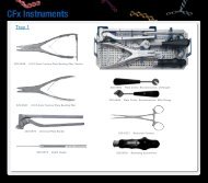
Surgical Guide - OsteoMed
Surgical Guide - OsteoMed
Surgical Guide - OsteoMed

Create successful ePaper yourself
Turn your PDF publications into a flip-book with our unique Google optimized e-Paper software.
hand plating system
Table of Contents<br />
hand plating system<br />
System Overview<br />
• 1.2mm Module ........................................................................................................ 2<br />
• 1.6mm Module ........................................................................................................ 4<br />
• 2.0mm Module ........................................................................................................ 6<br />
• 2.4mm Module ........................................................................................................ 8<br />
• Cannulated Module ............................................................................................ 10<br />
• Hand Fusion Module ......................................................................................... 12<br />
• Instruments ................................................................................................................. 14<br />
<strong>Surgical</strong> Technique<br />
• Plating - General ................................................................................................... 18<br />
• Plating - Dual Compression .......................................................................... 21<br />
• Plating - Cannulated Screw .......................................................................... 22<br />
• Plating - Subcondylar Plate .......................................................................... 23<br />
• Screw Fixation - Lag Screws ....................................................................... 24<br />
• Screw Fixation - Cannulated ...................................................................... 25<br />
• Hand Fusion ............................................................................................................... 27
1.2mm<br />
Module<br />
Plates<br />
333-1201 1.2mm 6 Hole Straight Plate<br />
333-1206 1.2mm 3 x 8 T Plate<br />
333-1202 1.2mm 12 Hole Straight Plate<br />
333-1207 1.2mm 4 x 8 T Plate<br />
333-1203 1.2mm Y Plate<br />
333-1208 1.2mm Offset Grid Plate, Left<br />
333-1204 1.2mm L Plate, Left<br />
333-1209 1.2mm Offset Grid Plate, Right<br />
333-1205 1.2mm L Plate, Right<br />
Screws<br />
331-12XX<br />
1.2mm x 4mm – 18mm Fully Threaded Screw<br />
332-12XX<br />
1.2mm x 6mm-18mm Lag Screw<br />
page 2
1.2mm<br />
Module<br />
Instruments<br />
320-1061 HPS 1.2mm Screw & Plate Module<br />
320-1210 1.0mm Drill, Manual<br />
320-1410 1.0mm Drill, J-Latch<br />
320-1610 1.0mm Drill, Quick Release<br />
320-1213 1.3mm Drill, Manual<br />
320-1413 1.3mm Drill, J-Latch<br />
320-1613 1.3mm Drill, Quick Release<br />
320-1001 1.2mm/1.6mm Plate Holding TAK<br />
320-1011 1.2mm/1.6mm Plate Holding Threaded TAK<br />
320-1009 1.2mm/1.6mm Countersink, Manual<br />
320-1112 1.2mm Screwdriver Shaft, Manual<br />
320-1512 1.2mm Screwdriver Sleeve<br />
page pg 3
1.6mm<br />
Module<br />
Plates<br />
333-1601 1.6mm 6 Hole Straight Plate, Locking<br />
333-1607 1.6mm 4 x 8 T Plate, Locking<br />
333-1602 1.6mm 12 Hole Straight Plate, Locking<br />
333-1608 1.6mm Offset Grid Plate, Left, Locking<br />
333-1603 1.6mm Y Plate, Locking<br />
333-1609 1.6mm Offset Grid Plate, Right, Locking<br />
333-1604 1.6mm L Plate, Left, Locking<br />
333-1611 1.6mm Condylar Plate, Left, Locking<br />
333-1605 1.6mm L Plate, Right, Locking<br />
333-1612 1.6mm Condylar Plate, Right, Locking<br />
333-1606 1.6mm 3 x 8 T Plate, Locking<br />
333-1620 1.6mm Subcondylar Plate, Locking<br />
333-1651 1.6mm 6 Hole Straight Plate, Locking, TiA*<br />
*Cannot be cut with HPS Plate Cutter<br />
333-1652 1.6mm Subcondylar Plate, Locking, TiA*<br />
Screws<br />
330-16xx 1.6mm x 6mm - 24mm Fully Threaded Screw, Angled Locking 308-16xx 1.6mm x 6mm - 24mm Lag Screw<br />
331-16xx<br />
1.6mm x 6mm - 24mm Fully Threaded Screw<br />
page 4
1.6mm<br />
Module<br />
Instruments<br />
320-1062 HPS 1.6mm Screw & Plate Module<br />
320-1213 1.3mm Drill, Manual<br />
320-1413 1.3mm Drill, J-Latch<br />
320-1613 1.3mm Drill, Quick Release<br />
320-1216 1.6mm Drill, Manual<br />
320-1416 1.6mm Drill, J-Latch<br />
320-1616 1.6mm Drill, Quick Release<br />
320-1001 1.2mm/1.6mm Plate Holding TAK<br />
320-1011 1.2mm/1.6mm Plate Holding Threaded TAK<br />
320-1009 1.2mm/1.6mm Countersink, Manual<br />
320-1116 1.6mm Screwdriver Shaft, Manual<br />
320-1516 1.6mm Screwdriver Sleeve<br />
page pg 5
2.0mm<br />
Module<br />
Plates<br />
333-2001 2.0mm 6 Hole Straight Plate, Locking<br />
333-2010 2.0mm Subcondylar Plate, Locking<br />
333-2002 2.0mm 12 Hole Straight Plate, Locking<br />
333-2011 2.0mm Condylar Plate, Left, Locking<br />
333-2003 2.0mm Y Plate, Locking<br />
333-2012 2.0mm Condylar Plate, Right, Locking<br />
333-2004 2.0mm L Plate, Left, Locking<br />
333-2013 2.0mm Z Plate, Locking<br />
333-2005 2.0mm L Plate, Right, Locking<br />
333-2020 2.0mm 4 Hole Straight LCDCP*<br />
333-2006 2.0mm 2 x 8 T Plate, Locking<br />
333-2021 2.0mm 6 Hole Straight LCDCP*<br />
333-2007 2.0mm 3 x 8 T Plate, Locking<br />
333-2022 2.0mm 8 Hole Straight LCDCP*<br />
333-2008 2.0mm Offset Grid Plate, Left, Locking<br />
333-2051 2.0mm 6 Hole Straight Plate, Locking, TiA*<br />
333-2009 2.0mm Offset Grid Plate, Right, Locking<br />
333-2052 2.0mm Subcondylar Plate, Locking, TiA*<br />
*Cannot be cut with HPS Plate Cutter<br />
page 6
2.0mm<br />
Module<br />
Screws<br />
330-20xx 2.0mm x 6mm - 36mm Fully Threaded Screw, 302-20xx 2.0mm x 6mm - 36mm Lag Screw<br />
Angled Locking<br />
331-20xx<br />
2.0mm x 6mm - 36mm Fully Threaded Screw<br />
Instruments<br />
320-1063 HPS 2.0mm Screw & Plate Module<br />
320-1215 1.5mm Drill, Manual<br />
320-1415 1.5mm Drill, J-Latch<br />
320-1615 1.5mm Drill, Quick Release<br />
320-1715 1.5mm Drill, Quick Release, Short<br />
320-1220 2.0mm Drill, Manual<br />
320-1420 2.0mm Drill, J-Latch<br />
320-1620 2.0mm Drill, Quick Release<br />
320-1720 2.0mm Drill, Quick Release, Short<br />
320-1002 2.0mm/2.4mm Plate Holding TAK<br />
320-1012 2.0mm/2.4mm Threaded Plate Holding TAK<br />
320-1010 2.0mm/2.4mm Countersink, Manual<br />
320-1120 2.0mm Screwdriver Shaft, Manual<br />
320-1520 2.0mm Screwdriver Sleeve<br />
page pg 7
2.4mm<br />
Module<br />
Plates<br />
333-2401 2.4mm 6 Hole Straight Plate, Locking<br />
333-2410 2.4mm Subcondylar Plate, Locking<br />
333-2402 2.4mm 12 Hole Straight Plate, Locking<br />
333-2411 2.4mm Condylar Plate, Left, Locking<br />
333-2403 2.4mm Y Plate, Locking<br />
333-2412 2.4mm Condylar Plate, Right, Locking<br />
333-2404 2.4mm L Plate, Left, Locking<br />
333-2413 2.4mm Z Plate, Locking<br />
333-2405 2.4mm L Plate, Right, Locking<br />
333-2420 2.4mm 4 Hole Straight LCDCP*<br />
333-2406 2.4mm 2 x 8 T Plate , Locking<br />
333-2421 2.4mm 6 Hole Straight LCDCP*<br />
333-2407 2.4mm 3 x 8 T Plate , Locking<br />
333-2422 2.4mm 8 Hole Straight LCDCP*<br />
333-2408 2.4mm Offset Grid Plate, Left, Locking<br />
333-2451 2.4mm 6 Hole Straight Plate, TiA*<br />
333-2409 2.4mm Offset Grid Plate, Right, Locking<br />
333-2452 2.4mm Subcondylar Plate, TiA*<br />
*Cannot be cut with HPS Plate Cutter<br />
page 8
2.4mm<br />
Module<br />
Screws<br />
330-24xx 2.4mm x 6mm - 36mm Fully Threaded Screw, 306-24xx 2.4mm x 6mm - 36mm Lag Screw<br />
Angled Locking<br />
331-24xx 2.4mm x 6mm - 36mm Fully Threaded Screw 330-1818 1.8mm x 18mm Locking Buttress Pin<br />
Instruments<br />
320-1064 HPS 2.4mm Screw & Plate Module<br />
320-1220 2.0mm Drill, Manual<br />
320-1420 2.0mm Drill, J-Latch<br />
320-1620 2.0mm Drill, Quick Release<br />
320-1720 2.0mm Drill, Quick Release, Short<br />
320-1224 2.4mm Drill, Manual<br />
320-1424 2.4mm Drill, J-Latch<br />
320-1624 2.4mm Drill, Quick Release<br />
320-1002 2.0mm/2.4mm Plate Holding TAK<br />
320-1012 2.0mm/2.4mm Threaded Plate Holding TAK<br />
320-1010 2.0mm/2.4mm Countersink, Manual<br />
320-1124 2.4mm Screwdriver Shaft, Manual<br />
320-1524 2.4mm Screwdriver Sleeve<br />
page pg 9
Cannulated<br />
Module<br />
K-Wire<br />
316-0133 .028” x 4” K-Wire<br />
316-0107 .035” x 4” K-Wire<br />
316-0119 .035” x 4” K-Wire, Double Trocar<br />
316-0003 .045” x 4” K-Wire<br />
316-0123 .045” x 4” K-Wire, Double Trocar<br />
Screws<br />
319-20xx 2.0mm x 6mm - 36mm Cannulated Lag Screw 317-20xx 2.0mm x 10mm - 36mm Cannulated Headless Screw<br />
319-24xx 2.4mm x 6mm - 36mm Cannulated Lag Screw 317-24xx 2.4mm x 10mm - 36mm Cannulated Headless Screw<br />
317-30xx<br />
3.0mm x 10mm - 36mm Cannulated Headless Screw<br />
page 10
Cannulated<br />
Module<br />
Instruments<br />
320-1055 HPS Cannulated Screw Module<br />
316-0116 1.7mm Cannulated Drill, Long, Manual<br />
316-0014 1.7mm Cannulated Drill, Long, Quick Release<br />
316-0322 2.4mm Proximal Cortex Drill, Manual<br />
316-0323 2.4mm Proximal Cortex Drill, Quick Release<br />
316-0005 2.3mm Cannulated Drill, Manual<br />
316-0015 2.3mm Cannulated Drill, Quick Release<br />
316-0317 2.9mm Proximal Cortex Drill, Manual<br />
316-0035 2.0/2.4/3.0/4.0mm Cannulated Drill <strong>Guide</strong><br />
316-0101 2.0/2.4mm Cannulated Screw Countersink<br />
316-0135 HPS Dual Cannulated Depth Gauge<br />
316-0310 2.0/2.4mm Headless Tri-lobe Driver, Cannulated, Tapered, Manual<br />
316-0308 2.0/2.4mm Headless Tri-lobe Driver, Tapered, Manual<br />
316-0311 3.0/4.0mm Headless Driver, Cannulated, Tapered, Manual<br />
316-0309 3.0/4.0mm Headless Driver, Solid, Tapered<br />
316-0102 2.0/2.4mm Cannulated Driver, Manual<br />
316-0039 2.0/2.4/3.0/4.0mm Cannulated Screw Remover<br />
page 11
Hand Fusion<br />
Module<br />
2.0mm Fusion Screws*<br />
2.4mm Fusion Screws*<br />
334-20xx<br />
2.0 x16 - 32mm Fusion Screw<br />
334-24xx<br />
2.4 x 20 - 36mm Fusion Screw<br />
Hand Fusion Plates*<br />
333-1614 1.6mm Fusion Plate<br />
333-2014 2.0mm Fusion Plate<br />
K-Wire<br />
316-0107 .035 x 4” K-Wire Single Trocar<br />
316-0119 .035” x 4” K-Wire Double Trocar<br />
316-0003 .045 x 4” K-Wire Single Trocar<br />
316-0123 .045 x 4” K-Wire Double Trocar<br />
page 12<br />
Patent Pending*
Hand Fusion<br />
Module<br />
Instruments<br />
320-1065 HPS Hand Fusion Screw & Plate Module<br />
320-1040 Goniometer<br />
316-1046 Depth Gauge<br />
316-1041 20°/25° Fusion Reamer<br />
316-1042 30°/35° Fusion Reamer<br />
316-1043 40°/45° Fusion Reamer<br />
316-1044 50°/55° Fusion Reamer<br />
316-1045-03 K-Wire <strong>Guide</strong><br />
316-1045 K-Wire <strong>Guide</strong><br />
316-1017 1.7mm Drill, Quick Release<br />
316-0917 1.7mm Drill, Manual<br />
316-1020 2.0mm Drill, Quick Release<br />
316-0920 2.0mm Drill, Manual<br />
316-1120 2.0mm Fusion Screw Driver Stem<br />
316-1124 2.4mm Fusion Screw Driver Stem<br />
page 13
General Instrumentation Tray<br />
320-1050 HPS Instrument Tray 320-1060 HPS Two Instrument Tray<br />
Bone and Soft Tissue Management<br />
Selected to aid in fracture realignment and positioning<br />
320-1020 6mm Hohmann Retractor<br />
320-1021 8mm Hohmann Retractor<br />
320-1022 3mm Periosteal Elevator, Straight Edge<br />
320-1023 3mm Periosteal Elevator, Curved Edge<br />
320-1024 Sharp Hook<br />
320-1017 Reduction Forceps<br />
320-1019 Termite Forceps<br />
320-1018 Reduction Forceps, K-wire <strong>Guide</strong><br />
page 14
General Instrumentation Tray<br />
Plate Altering<br />
Designed to easily alter plates to fit varying patient anatomy.<br />
320-1015 Universal Plate Cutter<br />
320-1016 Plate Benders<br />
Plate Holding<br />
intended to facilitate implantation by temporarily securing the plate to the bone<br />
320-1032 On Bone Plate Holder<br />
320-1033 Plate Holding Forcep, Swivel Foot<br />
page 15
General Instrumentation Tray<br />
Screw Insertion<br />
Precise instrumentation for adequate fixation<br />
320-1003 1.2mm Fully Threaded Screw Drill <strong>Guide</strong><br />
320-1004 1.6mm Fully Threaded Screw Drill <strong>Guide</strong><br />
320-1005 2.0mm Fully Threaded Screw Drill <strong>Guide</strong><br />
320-1006 2.4mm Fully Threaded Screw Drill <strong>Guide</strong><br />
320-1013 1.2/1.6mm Screw Depth Gauge<br />
320-1014 2.0/2.4mm Screw Depth Gauge<br />
316-0048 Ratchet Screwdriver Handle<br />
316-0049 Swivel Screwdriver Handle<br />
220-0027 Small Grasping Forceps<br />
page 16
Instrument Tips<br />
• Plate Holding Taks in plate modules can be inserted into plate holes with a wire pin driver to<br />
temporarily fixate plate.<br />
• Plate Holding Forcep and On Bone Plate Holders are available to help stabilize plate.<br />
• Screwdriver shafts are self retaining. Insert Screwdriver straight with force to engage head of<br />
screw. To remove driver tip from screw, rock it slightly from side to side and lift.<br />
• Use Driver Sleeve to protect soft tissue during screw insertion when necessary and to provide<br />
stability while driving in longer screws.<br />
• Countersinks are provided for use when placing a headed screw outside a plate. They are<br />
recommended in cases of dense bone to create recess for head of screw.<br />
• Proximal Cortex Drills are provided for use with Headless Cannulated Screws. They are<br />
recommended to create a larger pilot hole for trailing end of screw.<br />
• Cannulated Depth Gauge has two sides. “On Plate” side has a flat tip and is designed to hit<br />
surface of plate. “On Bone” side is pointed to allow for accurate measurements at any position.<br />
• Hand Fusion Depth Gauge is double sided and calibrated for 2.0mm or 2.4mm fusion screw holes.<br />
• Universal Plate Cutter<br />
• Place last needed hole around appropriately sized post.<br />
• Pull plate slightly so it grasps post.<br />
• Hold plate securely with one hand and squeeze handles to cut plate.<br />
• Silicone on cutting tip will hold unused part of plate.<br />
• Remove any plate pieces from silicone before proceeding.<br />
• Inspect plate for burrs and remove using file located on top of instrument.<br />
• If cutting pins or tines, use middle section of Universal Plate Cutter marked with black circle.<br />
• K-wires .045” (1.2mm) or smaller can be cut using tip of Universal Plate Cutter.
surgical technique<br />
hand plating system<br />
Plating<br />
General<br />
Preparation<br />
1<br />
Expose and reduce fracture or osteotomy site<br />
Plate Preparation and Positioning<br />
2<br />
Select plate<br />
Select appropriate plate size and configuration.<br />
3<br />
Cut plate<br />
If necessary plates may be cut using universal plate<br />
cutter, unless noted with * on pages 4-8.<br />
4<br />
Contour plate<br />
Plates are precontoured to anatomically fit bone. If further<br />
contouring is necessary, plate benders may be used.<br />
NOTE: Bending plate multiple times may weaken<br />
plate and could result in implant failure.<br />
page 18
Plating<br />
General<br />
5<br />
Position plate<br />
Position plate over fracture or osteotomy. Use plate<br />
holding TAKs for temporary fixation during procedure.<br />
Screw Preparation and Insertion<br />
6<br />
Determine desired screw type<br />
Angled locking, non-locking, lag, or cannulated lag.<br />
Steps 7-10 are for angled locking, non-locking and<br />
lag Screws. Directions for using cannulated lag screws<br />
and compression holes on pages 21-22.<br />
7<br />
Drill<br />
Select appropriate color coded drill guide and insert<br />
into plate hole nearest fracture or osteotomy site.<br />
Determine desired angle of screw placement. Ensure<br />
that screws do not converge.<br />
Drill a pilot hole using the appropriate pilot drill size.<br />
Note: Use irrigation when drilling. Fluoroscopy is<br />
recommended during drilling. In cases of soft bone<br />
drilling with smaller drill (from module 1 size down) is<br />
recommended.<br />
plate size<br />
angled locking<br />
ranges<br />
1.6mm + 22°<br />
2.0mm<br />
2.4mm<br />
+ 18°<br />
+ 17°<br />
While screw heads are designed to sit flush with plate,<br />
screw head prominence will vary at severe angles.<br />
Screw head prominence can cause soft tissue irritation.<br />
Angled-locking screws will lock at any angle that drill<br />
guide will allow when fully inserted into plate hole.<br />
Please refer to chart for locking angle ranges.<br />
page 19
Plating<br />
General<br />
8<br />
Measure<br />
Insert depth gauge until it passes through distal<br />
cortex. Retract stem until lip catches against bone to<br />
determine measurement.<br />
Screw Insertion<br />
9<br />
Select & insert<br />
Select desired screw diameter and length. Verify<br />
screw length with gauge on block. Insert screw into<br />
plate hole at desired angle to fixate plate onto bone.<br />
Fluoroscopy is recommended during screw insertion<br />
to ensure correct length and angulation.<br />
NOTE: When inserting angled locking screws at<br />
maximum angles stop inserting screw when head has<br />
engaged plate hole. Continuing to drive screw may<br />
cause screw to go through plate. Locking screws and<br />
plate holes can be used up to 3 times.<br />
10<br />
Repeat steps 6-9 for angled locking,<br />
non-locking and solid core lag screws until all<br />
necessary holes are filled.<br />
Close<br />
11<br />
Close treatment site using standard closure techniques<br />
page 20
Using Dual Compression Holes<br />
Plating<br />
Dual Compression<br />
1.6mm, 2.0mm and 2.4mm plates contain dual-compression holes, allowing for compression regardless<br />
of plate orientation.<br />
Anchor Screw<br />
1<br />
Select hole<br />
Begin with compression holes closest to fracture line.<br />
Compression hole<br />
2<br />
3<br />
4<br />
5<br />
Position drill guide<br />
Place drill guide eccentrically farthest from fracture.<br />
Drill<br />
Measure<br />
Partially insert screw<br />
Do not engage the plate with the screw head.<br />
Compression Screw<br />
6<br />
7<br />
Prepare Compression<br />
Follow steps 1-4 for compression hole opposite fracture.<br />
Fully insert screw<br />
Fully insert screw until head sits in center of<br />
compression hole.<br />
Final Compression<br />
8<br />
9<br />
Return to first screw and tighten<br />
Insert remaining screws following the general plating technique.<br />
NOTE: 1mm of compression is available with each<br />
compression hole. If only 1mm is needed, fully insert a<br />
screw on one side of the fracture and follow compression<br />
instructions for second screw (Steps 6-7).<br />
page pg 21
Plating<br />
Cannulated Screw<br />
Using Cannulated Lag Screws in a plate<br />
If using a cannulated lag screw through a plate, it must be inserted first before any other screw. Only one cannulated<br />
lag screw can be used per plate.<br />
1<br />
Insert K-wire<br />
Insert .035” K-wire through center of desired hole,<br />
perpendicular to fracture or place plate over kwire<br />
already in place. 1.2mm drill guide for 1.0mm pilot drill<br />
can be used as K-wire guide.<br />
NOTE: Do not bend K-wire when inserting into bone.<br />
2<br />
Measure<br />
Slide plate side of cannulated depth gauge over K-wire<br />
until tip bottoms out on plate; end of K-wire<br />
indicates screw length required. Subtract for any<br />
anticipated interfragmentary compression resulting<br />
from screw insertion.<br />
3<br />
Drill<br />
HPS cannulated screws are self drilling and self tapping,<br />
but drilling is recommended in cases of dense bone.<br />
If drilling is desired or necessary, select 1.7mm<br />
cannulated drill and use 2.0/2.4mm drill guide<br />
located in the cannulated block to drill pilot hole.<br />
4<br />
Insert screw<br />
Select diameter and length of screw needed. Verify<br />
screw length with gauge on block. Insert cannulated<br />
screw over K-wire through plate hole to fixate plate<br />
onto bone and compress the fracture.<br />
5<br />
6<br />
Remove and discard K-wire.<br />
Fill remaining screw holes with solid core screws.<br />
page 22
Plating<br />
Subcondylar Plate<br />
The Subcondylar Plate<br />
The subcondylar plate is designed with a 12° bend in order to sit below the condyles. The 12° bend allows screws<br />
to be placed at broader angles in order to fixate the fracture.<br />
1<br />
2<br />
Place plate<br />
Position the plate proximal to the condyle.<br />
Insert positioning screw<br />
Subcondylar plate has a positioning hole<br />
to aid in precise placement. Drill accentrically, furthest<br />
from plate bend. Measure and insert screw. Do not fully<br />
seat head of screw.<br />
Positioning hole<br />
3<br />
4<br />
5<br />
Insert screws into bent part of plate<br />
Follow steps 6-9 from general plating technique.<br />
Tighten screw in positioning hole<br />
Fill remaining screw holes. Following<br />
general plating instructions<br />
Alternative Condylar Blade Plates are available in 1.6mm, 2.0mm and 2.4mm for indications in<br />
which lateral condylar support and pins/tines are necessary. Instructions for implantation of condylar plates<br />
are as follows:<br />
Drill and measure depth, starting with pin/tine holes first. The 1.6mm and 2.0mm plates have tines<br />
that insert into condyle of bone next to screw. The 2.4mm plates have an angled-locking pin. Cut<br />
pin/tine to desired length using middle section of plate cutter marked by a dark circle.<br />
page 23
Screw Fixation<br />
Lag Screws<br />
Compression with Lag Screws<br />
Lag screws are provided for applications where compression across the fracture line by a screw is advantageous.<br />
Overdrills are also provided to create a gliding hole in the proximal fragment to achieve a lag effect with a<br />
fully threaded screw. To achieve compression, the screw must be placed perpendicular to the fracture line, and<br />
threads must pass into the distal fragment.<br />
1<br />
Drill<br />
Create pilot hole using the appropriate color coded drill<br />
guide and the appropriate pilot drill.<br />
2<br />
Countersink<br />
Countersink to create a recess for screw head.<br />
NOTE: If using a lag screw through a plate, countersink<br />
is not needed.<br />
3<br />
Measure<br />
4<br />
Insert screw<br />
Select appropriate screw diameter and length. Verify<br />
length with gauge on block. Insert screw into hole<br />
perpendicular to fracture/osteotomy. Repeat steps 2 – 5<br />
for additional screw placement.<br />
5<br />
Close the treatment site using standard<br />
closure techniques<br />
page 24
Cannulated Compression Screws - Headed and Headless<br />
Screw Fixation<br />
Cannulated Screws<br />
HPS has 2.0mm and 2.4mm headed cannulated and 2.0mm, 2.4mm and 3.0mm headless cannulated<br />
compression screws. Headless screws provide between 1-2mm of compression. Tapered tri-lobe<br />
driver stems allow headless screws to be inserted below the surface of the bone.<br />
Screw Preparation<br />
1<br />
Insert K-wire<br />
Insert the K-wire to the appropriate depth under<br />
fluoroscopy. Do not bend the K-wire when placing it in<br />
the bone.<br />
2<br />
Measure<br />
Slide on bone side of cannulated depth gauge over<br />
K-wire until tip bottoms out on bone; end of K-wire<br />
will indicate screw length required. Subtract<br />
appropriately for any anticipated interfragmentary<br />
compression resulting from screw insertion.<br />
3<br />
Drill (optional)<br />
HPS cannulated screws are self drilling and self<br />
tapping, but drilling is recommended in cases of<br />
dense bone. If drilling is desired or necessary,<br />
select the appropriate cannulated drill and use the<br />
cannulated drill guide located in the cannulated<br />
block to drill a pilot hole.<br />
NOTE: Use irrigation when pilot drilling.<br />
page 25
Screw Fixation<br />
Cannulated<br />
4<br />
Countersink or Proximal Cortex Drill<br />
Countersinking is recommended when using a<br />
cannulated lag screw to create the required recess in<br />
the bone.<br />
Proximal cortex drill is recommended when using<br />
headless screws to create a pilot hole for trailing end<br />
of screw.<br />
Insert Screw<br />
5<br />
Insert screw<br />
Select screw diameter and length. Verify screw length<br />
with gauge on block. Place screw over K-wire and<br />
use the screwdriver to drive cannulated screw into<br />
bone until desired compression is achieved. Headless<br />
screws will provide 1-2mm of compression.<br />
6<br />
7<br />
Remove and discard K-wire<br />
Repeat steps 1-6 for additional screw<br />
placement<br />
Closure<br />
8<br />
Close the treatment site using standard<br />
closure techniques<br />
page 26
Hand Fusion<br />
Hand Fusion<br />
Hand fusion allows for stable fixation of a joint at a natural resting angle between 20-55°. It combines the<br />
locking plate stability from HPS with the compression provided by the headless screws.<br />
Joint Preparation<br />
1<br />
Expose joint<br />
Make incision on dorsal surface of<br />
proximal bone of PIP joint.<br />
2<br />
Remove damaged joint surfaces<br />
Using goniometer for reference, position joint<br />
at desired angle (between 20-55 degrees) and<br />
create osteotomy cuts. Distal bone should be cut<br />
perpendicular to dorsal surface; proximal bone<br />
cut will determine angle of fusion. Cup and<br />
cone configuration can also be used.<br />
3<br />
Create guide channel in distal canal<br />
From center of joint, drive Ø.045” x 4”<br />
K-wire into distal bone axially to create a<br />
guide channel.<br />
NOTE: In soft bone where drilling for fusion screw<br />
will not be needed, Ø.035” x 4” K-wire can be used<br />
to create a smaller channel. Do not bend k-wire<br />
when inserting into bone.<br />
page pg 27
Hand Fusion<br />
4<br />
Remove<br />
K-wire from<br />
distal bone<br />
5<br />
Place K-wire to determine plate<br />
placement<br />
From center of joint, drive Ø.045” x<br />
4” K-wire into proximal bone through<br />
dorsal cortex at desired angle.<br />
6<br />
Confirm fusion angle<br />
Retrograde K-wire into channel of distal<br />
bone, re-attaching joint. Use goniometer<br />
to confirm angle.<br />
NOTE: Measuring the angle of the K-wire in the<br />
proximal bone relative to the dorsal surface will<br />
also determine fusion angle.<br />
page 28
Hand Fusion<br />
Plate Placement<br />
7<br />
Create a recess in proximal bone for<br />
placement of plate<br />
Select appropriate reamer based on<br />
angle of fusion desired. Place reamer<br />
over K-wire and ream using power, until<br />
top distal edge contacts surface of<br />
bone.<br />
8<br />
Place Fusion Plate<br />
Remove k-wire for direct access to the proximal<br />
holes. Select appropriate size fusion plate for<br />
fixation of joint. Cut and bend plate as needed<br />
using appropriate instrumentation from HPS<br />
instrument tray. Place plate in divet created by<br />
reamer with transfix hole distal on bone.<br />
9<br />
Fixate plate to proximal bone<br />
Follow Screw Preparation and Insertion steps in<br />
HPS <strong>Surgical</strong> Technique (page 17-18) to insert one<br />
locking, non-locking or lag screw from<br />
appropriate HPS module into shaft of plate.<br />
• 1.6 plates use screws from<br />
green 1.6 HPS module<br />
• 2.0 plates use screws from<br />
purple 2.0 HPS module<br />
NOTE: Do not place screw in hole in barrel of plate<br />
prior to placing Fusion Screw.<br />
page pg 29
Hand Fusion<br />
10<br />
Position bones for fusion<br />
Insert Ø.035 K-wire through transfix hole<br />
and position bones for fusion. Check<br />
positioning under fluoroscopy if desired.<br />
NOTE: Fusion screw WILL NOT fit over Ø.045<br />
K-wire previously used.<br />
11<br />
Measure<br />
Slide cannulated depth gauge over K-wire<br />
until tip reaches plate; end of K-wire<br />
will indicate screw length required.<br />
12<br />
Drill (optional)<br />
If drilling is desired, slide drill guide over K-wire<br />
into transfix hole. Drill hole using appropriate drill<br />
size. Fusion screws are self-drilling and self-tapping<br />
but drilling is recommended in dense bone.<br />
NOTE: Use irrigation when drilling. Fluoroscopy is<br />
recommended during drilling. Failure to use<br />
drill guide may inhibit ability to lock screw in<br />
plate.<br />
13<br />
Select Fusion Screw<br />
Select appropriate Fusion screw diameter and<br />
length from Hand Fusion module, 2.0mm screw<br />
for 1.6 plate and 2.4mm screw for 2.0 plate.<br />
Verify screw length with gauge on block.<br />
page 30
Hand Fusion<br />
Insert Fusion Screw<br />
14<br />
Insert Fusion Screw<br />
Reduce joint; insert screw over K-wire into transfix<br />
hole to compress joint and lock it into plate.<br />
NOTE: Firmly hold distal bone when inserting screw<br />
to prevent malrotation prior to compression and<br />
locking of screw into plate.<br />
15<br />
Optional Screws:<br />
If solid core screw is desired, use standard screws<br />
in 2.0 HPS module for transfix hole in 1.6 fusion<br />
plate, and standard screws in 2.4 HPS module for<br />
transfix hole in 2.0 fusion plate. Follow Screw<br />
Preparation and Insertion steps in HPS <strong>Surgical</strong><br />
Technique <strong>Guide</strong>. (page 17-18)<br />
Fill remaining screw holes<br />
Repeat step 9 to place additional screws until all<br />
necessary holes are filled.<br />
NOTE: If necessary, use only NON-LOCKING<br />
screws in hole in barrel of plate.<br />
Close<br />
16<br />
Place parallel K-wire or screw across joint<br />
if needed for anti-rotation. Close.<br />
MCP and DIP Joints<br />
The <strong>OsteoMed</strong> Hand Fusion System is approved for use in bone fusion and arthrodesis of phalanges<br />
and metacarpals. Fusion angles range between 20 and 55, and may be too extreme for the DIP joint. If<br />
choosing to fuse the DIP or MCP joint, follow the surgical technique for the PIP Joint.<br />
WARNING: In patients with a large intramedullary canal, the diameter length of the Fusion screw provided<br />
may not provide adequate compression of the MCP joint.<br />
page pg 31
OSTEOMED<br />
3885 Arapaho Rd.<br />
Addison, TX 75001<br />
Customer Service: 800.456.7779<br />
Outside the U.S.: 001.972.677.4600<br />
Fax: 800.390.2620<br />
Fax Outside the U.S.: 001.972.677.4709<br />
E-mail: customer.service@osteomed.com<br />
www.osteomed.com<br />
p/n 030-1616 Rev.C