NPC 2 Reconciliation Report
NPC 2 Reconciliation Report
NPC 2 Reconciliation Report

Create successful ePaper yourself
Turn your PDF publications into a flip-book with our unique Google optimized e-Paper software.
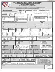
Date<br />
John Doe<br />
OSHPD<br />
Facilities Development Division<br />
400 R Street, Suite 200<br />
Sacramento, CA 95811<br />
Reference: Request for <strong>NPC</strong>‐2 Upgrade<br />
XYZ Hospital ‐ Medical Center, Facility ID XXXXX<br />
Address<br />
Dear Mr. Doe:<br />
The XYZ Hospital has undertaken X number of projects to comply with the nonstructural<br />
seismic compliance requirements of Article 11, Chapter 6, Part 1, Title 24. The work associated<br />
with these projects is complete and the projects have been closed with compliance. This letter,<br />
the application for “Request for <strong>NPC</strong> 2 Upgrade” (OSHPD form OSH-FD-121) and<br />
accompanying material represent a formal request for <strong>NPC</strong> 2 status for the XYZ Hospital.<br />
List of Buildings:<br />
Building Name OSHPD BLD Project # for Original Construction<br />
Main Wing BLD-xxxxx None<br />
Main Hospital BLD-xxxxx None<br />
Ancillary Wing BLD-xxxxx OSA H-xxxx<br />
Hospital Annex BLD-xxxxx OSHPD HS-970xxx<br />
Central Utility Plant BLD-xxxxx None<br />
The following items are presented in the attached CD as justification for granting <strong>NPC</strong> 2 status to<br />
the Subject Hospital:<br />
1. Drawings (“As-Built, including any modifications by change order):<br />
a. SS-951xxx Telephone System Upgrade Project<br />
b. SS-040xxx Emergency Power Supply Upgrade Project<br />
c. SS-070xxx New Day Tank Installation<br />
d. SS-877xxx Fire Alarm Upgrade Project<br />
e. SS-050xxx<strong>NPC</strong> 2 Upgrade Emergency Lighting<br />
2. 11x17 Site Plan (Appendix B)<br />
3. Supporting Photos (Appendix D)<br />
The Subject Hospital and its entire design team have worked to achieve the following two goals:<br />
(l) satisfying the requirements of the regulations; and (2) documenting our work in a manner that<br />
would facilitate the reconciliation process.<br />
Please contact me should you have any questions, need additional information, or if there is<br />
anything that any of us can do to facilitate your review.<br />
Sincerely,<br />
OSHPD Note for the Design Professional<br />
1. If the “as‐built”, set of drawings do not have<br />
the OSHPD stamp, then submit the original<br />
cover sheet which depicts the OSHPD approval<br />
stamp.
"<br />
Component Inventory<br />
Submitted to demonstrate compliance with<br />
SB1953 <strong>NPC</strong> X requirements<br />
Date<br />
The following Itemized list contains in a tabular format all components in<br />
the Subject Hospital that are subject to the requirements of <strong>NPC</strong> 2. The<br />
inventory was developed on a building- by-building basis though<br />
observation by the CA licensed Design professional X. Each item on the<br />
list has been either installed, retrofit or otherwise justified under an OSHPD<br />
permit.
Component Name<br />
or Description<br />
Location<br />
(Building/Yard)<br />
Room, Area<br />
Yard<br />
Method of Anchorage<br />
OSHPD<br />
Permit No.<br />
Detail<br />
Reference<br />
Anchorage/<br />
Bracing<br />
Compliant<br />
(Yes/No)<br />
Comments<br />
Telephone<br />
PBX Switchgear<br />
Ancillary Wing<br />
Telecom<br />
Room 145<br />
Anchored to Floor Slab SS‐951xxx 3/S4 Yes Telephone System serves all the buildings at the facility<br />
Telephone<br />
Battery Rack<br />
Ancillary Wing<br />
Telecom<br />
Room 145<br />
Anchored to Floor Slab<br />
SS‐951xxx<br />
4/S4<br />
Photos<br />
C‐1 & C‐2<br />
Yes<br />
Batteries are secure within the shelves of vertical rack<br />
Telephone<br />
Battery Rectifier<br />
Ancillary Wing<br />
Telecom<br />
Room 145<br />
Anchored to Floor Slab SS‐951xxx 5/S4 Yes Internal System<br />
Communication System (Internal)<br />
Computer Console<br />
dedicated to Telephone<br />
Computer Monitor<br />
dedicated to Telephone<br />
Telephone Backboard<br />
Main Hospital<br />
Main Hospital<br />
Main Hospital<br />
Telecom<br />
Room 153<br />
Telecom<br />
Room 153<br />
Telecom<br />
Room 153<br />
Anchored to Floor<br />
Anchored to Desk top<br />
Overhead Page Hospital Annex Corridor Wall Mounted<br />
PIN 32<br />
Item 3<br />
PIN 32<br />
Item 3<br />
See Plan<br />
Photo<br />
C‐3<br />
See Plan<br />
Photo<br />
C‐4<br />
Yes<br />
Yes<br />
Wall Mounted SS‐951xxx 10/S4 Yes<br />
PIN 32<br />
Item 3<br />
See Plan<br />
Photo<br />
C‐5<br />
Yes<br />
Console weighs < 20lbs<br />
located under desk and strapped to the floor<br />
Component weighs < 20lbs,<br />
sits atop the desk and is strapped to the desk<br />
Component can be activated by a various phones<br />
Component weighs < 20lbs<br />
Component is secured to a shelf with a strap<br />
Shelf is supported by two L‐shaped brackets<br />
Each Bracket is anchored to the wall with 2 anchors<br />
Amplifier Hospital Annex Room 350 Wall Mounted<br />
PIN 32<br />
Item 3<br />
See Plan<br />
Photo<br />
C‐6<br />
Yes<br />
Component weighs < 20lbs<br />
Component is secured to the shelf with snub angles<br />
Shelf is supported by two L‐shaped brackets<br />
Each Bracket is anchored to the wall with 2 anchors<br />
Speakers<br />
Main Hospital<br />
All<br />
Corridors<br />
Ceiling Mounted<br />
PIN 32<br />
Item 3<br />
4/S4<br />
Photos<br />
C‐8 & C‐9<br />
Yes<br />
Components weight < 20lbs<br />
Visually inspected 5 speaker and anchorage is positive<br />
OSHPD Notes for Design Professional<br />
1. The telephone system was selected as the internal communication system. The telephone could also serve as the external system<br />
The common components of the telephone system are listed above<br />
2. Note that the within the comment section the buildings served by the system is stated. In this example, all the buildings in the facility are served by the telephone system.<br />
3. Nurse call system may also be included<br />
4. PIN 32, item 3 is a common method for verifying existing and compliant anchorage for components that weigh less than 20 lbs.<br />
Review PIN 32 for exceptions
Component Name<br />
or Description<br />
Location<br />
(Building/Yard)<br />
Room, Area<br />
Yard<br />
Method of<br />
Anchorage<br />
OSHPD<br />
Permit No.<br />
Detail<br />
Reference<br />
Anchorage/<br />
Bracing<br />
Compliant<br />
(Yes/No)<br />
Comments<br />
Communication System<br />
(External)<br />
Sample System One<br />
HEAR Radio<br />
Console<br />
HEAR Radio<br />
Dedicated Monitor<br />
HEAR Radio<br />
External Antenna<br />
Main Hospital Room 130<br />
Main Hospital Room 130<br />
Main Hospital<br />
Rooftop<br />
Anchored to<br />
Floor Slab<br />
Anchored to<br />
Desktop<br />
Anchored to<br />
Concrete Wall<br />
PIN 32<br />
Item 3<br />
PIN 32<br />
Item 3<br />
PIN 32<br />
Item 3<br />
See Plan<br />
Photo<br />
C‐9<br />
See Plan<br />
Photo<br />
C‐10<br />
See Plan<br />
Photo<br />
C‐11<br />
Yes<br />
Yes<br />
Yes<br />
Component weighs < 20lbs<br />
located under desk and strapped to the floor<br />
Component weighs < 20lbs<br />
secured to desktop with straps<br />
Lightweight Aluminum Antenna (
Emergency Power Supply System (EPSS)<br />
Component Name<br />
or Description<br />
Emergency Generator 1<br />
(EG‐1) 1000kW<br />
Generator<br />
EG‐1 Cooling System<br />
EG‐1 Muffler/Silencer<br />
EG‐1 Fuel Day Tank<br />
EG‐1 Battery Rack<br />
EG‐1 Battery Charger<br />
Emergency Generator 2<br />
(EG‐2) 750kW Generator<br />
Location<br />
(Building/Yard)<br />
Central Utility<br />
Plant<br />
Central Utility<br />
Plant<br />
Central Utility<br />
Plant<br />
Central Utility<br />
Plant<br />
Central Utility<br />
Plant<br />
Central Utility<br />
Plant<br />
Equipment Yard<br />
Room, Area<br />
Yard<br />
Method of Anchorage<br />
OSHPD<br />
Permit No.<br />
Detail<br />
Reference<br />
Anchorage/<br />
Bracing<br />
Compliant<br />
(Yes/No)<br />
Floor Level Anchored to Floor Slab SS‐040xxx 12/S2 Yes<br />
Floor Level Anchored to Floor Slab SS‐040xxx 13/S2 Yes<br />
Floor Level<br />
Suspended from Roof<br />
Structure Above<br />
Comments<br />
EG‐1 Serves Buildings:<br />
Main Wing, Main Hospital and Ancillary Building<br />
Diesel motor (prime mover)<br />
Radiator is adjacent to the generator and is anchored to the<br />
floor slab<br />
SS‐040xxx 13/S4 Yes Suspended Above with diagonal braces in each direction<br />
Floor Level Anchored to Floor Slab SS‐070xxx 1/S4 Yes New 75 gallon Fuel Tank<br />
Floor Level Anchored to Floor Slab SS‐040xxx 1/S2 Yes<br />
Floor Level Wall Mounted SS‐040xxx 2/S3 Yes<br />
Anchored to<br />
Frame of Enclosure<br />
HS‐970xxx 1/A2 Yes<br />
Batteries are secure inside rack. Rack is anchored to floor<br />
slab with two 1/4" diameter anchors<br />
EG‐2 serves Buildings:<br />
Hospital Annex, Central Utility Plant and Equipment Yard<br />
EG‐2 is an exterior generator located inside an enclosure.<br />
The enclosure was installed under an OSHPD permit HS‐<br />
970xxx<br />
EG‐2 Cooling System Equipment Yard Anchored to Generator HS‐970xxx 1/A2 Yes Cooling System is attached to the EG‐2 Frame<br />
EG‐2 Muffler/Silencer Equipment Yard<br />
EG‐2 Fuel Day Tank Equipment Yard<br />
EG‐2 Battery Rack Equipment Yard<br />
EG‐2 Battery Charger Equipment Yard<br />
Anchored to the exterior<br />
Frame of Enclosure<br />
Anchored to<br />
Frame of Enclosure<br />
Anchored to<br />
Frame of Enclosure<br />
Anchored to<br />
Frame of Enclosure<br />
HS‐970xxx 1/A2 Yes<br />
Muffler/Silencer is exposed and above the enclosure.<br />
Anchorage is present and is not rusted<br />
HS‐970xxx 1/A2 Yes 50 gallon Horizontal tank, anchored within the enclosure<br />
HS‐970xxx 1/A2 Yes<br />
Batteries are secure in a floor rack. Rack is anchored to<br />
generator enclosure<br />
HS‐970xxx 1/A2 Yes Part of Battery Rack Assembly<br />
Fuel Pump Equipment Yard Anchored to Floor Slab HS‐970xxx 1/M4 Yes Provides fuel to Day Tanks (EG‐1 and EG‐2)<br />
Main Fuel Tank<br />
12,000 gallons<br />
Automatic Transfer<br />
Switch<br />
(ATS)<br />
Equipment Yard Below Grade HS‐970xxx 1/A2 Yes<br />
Central Utility<br />
Plant<br />
OSHPD Notes for Design Professional<br />
1. Common components of the Emergency Power Supply System are shown<br />
Floor Level Anchored to Floor Slab HS‐970xxx 15/E6 Yes<br />
Provides fuel to Day Tanks (EG‐1 and EG‐2)<br />
Located on Site Plan<br />
Signals EG‐1 and EG‐2 to start at the loss of Normal Power<br />
Located on Site Plan
Bulk Medical Gas System<br />
(BMG)<br />
Component Name<br />
or Description<br />
Location<br />
(Building/Yard)<br />
Room, Area<br />
Yard<br />
Method of Anchorage<br />
OSHPD<br />
Permit No.<br />
Detail<br />
Reference<br />
Anchorage/<br />
Bracing<br />
Compliant<br />
(Yes/No)<br />
Comments<br />
Main Liquid O 2 Tank Equipment Yard Anchored to Foundation SS‐877xxx 5/S15 Yes Located on Site Plan<br />
Reserve Liquid O 2 Tank Equipment Yard Anchored to Foundation SS‐877xxx 6/S15 Yes Located on Site Plan<br />
Vaporizers #1 Equipment Yard Anchored to Foundation SS‐877xxx 6/S15 Yes Located on Site Plan<br />
Vaporizers #2 Equipment Yard Anchored to Foundation SS‐877xxx 6/S15 Yes Located on Site Plan<br />
Vaporizers #3 Equipment Yard Anchored to Foundation SS‐877xxx 6/S15 Yes Located on Site Plan<br />
Nitrous Oxide Tank Equipment Yard Anchored to Foundation SS‐877xxx 6/S15 Yes Located on Site Plan<br />
Manifold/Relief Devices Equipment Yard Anchored to Foundation SS‐877xxx 9/S18 Yes<br />
Anchored to elevated series of rails.<br />
Rails are anchored per listed OSHPD project<br />
OSHPD Notes for Design Professional<br />
1. Common components of the Bulk Medical Gas System are shown
Fire Alarm System<br />
Component Name<br />
or Description<br />
Main Fire Alarm<br />
Control Panel<br />
(FACP)<br />
Fire Alarm Sub‐Panel<br />
Annunciator<br />
Fire Alarm Sub‐Panel<br />
Fire Alarm Sub‐Panel<br />
Supplemental Power<br />
Supply<br />
Location<br />
(Building/Yard)<br />
Main Wing<br />
Main Wing<br />
Main Hospital<br />
Main Hospital<br />
Main Hospital<br />
Room, Area<br />
Yard<br />
Electrical Room<br />
101<br />
Elevator/Lobby<br />
Area‐ 1st Floor<br />
Elevator/Lobby<br />
Area‐ 3rd Floor<br />
Elevator/Lobby<br />
Area‐ 3rd Floor<br />
Elevator/Lobby<br />
Area‐ 5th Floor<br />
Method of Anchorage<br />
OSHPD<br />
Permit No.<br />
Detail<br />
Reference<br />
Anchorage/<br />
Bracing<br />
Compliant<br />
(Yes/No)<br />
Wall Mounted SS‐877xxx 5/F2 Yes<br />
Wall Mounted<br />
Wall Mounted<br />
Wall Mounted<br />
Wall Mounted<br />
Fire Alarm Sub‐Panel Ancillary Wing 1st Floor Wall Mounted ‐<br />
Annunciator Ancillary Wing 1st Floor Wall Mounted ‐<br />
Annunciator Main Wing 1st Floor Wall Mounted<br />
Fire Alarm Sub‐Panel Hospital Annex 1st Floor Wall Mounted<br />
Annunciator Hospital Annex 1st Floor Wall Mounted<br />
OSHPD Notes for Design Professional<br />
1. List the buildings served by the Fire Alarm Control Panel. 2. Plans are not shown on the Sample <strong>Report</strong><br />
2. Plans are not shown on the Sample <strong>Report</strong><br />
PIN 32<br />
Item 4<br />
PIN 32<br />
Item 4<br />
PIN 32<br />
Item 4<br />
PIN 32<br />
Item 4<br />
PIN 32<br />
Item 4<br />
PIN 32<br />
Item 4<br />
PIN 32<br />
Item 4<br />
See Plan &<br />
Photo FS‐1<br />
See Plan &<br />
Photo FS‐2<br />
See Plan &<br />
Photo FS‐3<br />
See Plan &<br />
Photo FS‐4<br />
H‐xxxx<br />
Detail 2/F4<br />
H‐xxxx<br />
Detail 3/FS‐<br />
4<br />
See Plan &<br />
Photo FS‐5<br />
See Plan &<br />
Photo FS‐6<br />
See Plan &<br />
Photo FS‐7<br />
Yes<br />
Yes<br />
Yes<br />
Yes<br />
Yes<br />
Yes<br />
Yes<br />
Yes<br />
Yes<br />
Comments<br />
FACP serves the following buildings; Main Hospital, Hospital Annex, Ancillary<br />
Wing and Main Wing. FACP was connected to existing Fire Alarm System at<br />
the Ancillary Building. Components of the Existing System are identified in the<br />
report and anchorage is verified per PIN 32<br />
Panel is attached to metal stud framing<br />
Panel has one fastener at each corner<br />
Panel weighs < 100lbs and is 10" x 6" x 6" deep<br />
See attached statement as required per PIN 32, item 4d<br />
Panel is attached to metal stud framing<br />
Panel has one fastener at each corner<br />
Panel weighs < 100lbs and is 8" x 4" x 4" deep<br />
See attached statement as required per PIN 32, item 4d<br />
Panel is attached to metal stud framing<br />
Panel has one fastener at each corner<br />
Panel weighs < 100lbs and is 10" x 6" x 6" deep<br />
See attached statement as required per PIN 32, item 4d<br />
Panel is attached to metal stud framing<br />
Panel has one fastener at each corner<br />
Panel weighs < 100lbs and is 10" x 6" x 6" deep<br />
See attached statement as required per PIN 32, item 4d<br />
OSA Project H‐xxxx<br />
Component was verified to be anchored and with reasonable compliance to<br />
the existing drawings. See attached stamped and signed statement by the<br />
structural engineer of record<br />
OSA Project H‐xxxx<br />
Component was verified to be anchored and with reasonable compliance to<br />
the existing drawings. See attached stamped and signed statement by the<br />
structural engineer of record<br />
Panel is attached to metal stud framing<br />
Panel has one fastener at each corner<br />
Panel weighs < 100lbs and is 8" x 4" x 4" deep<br />
See attached statement as required per PIN 32, item 4d<br />
Panel is attached to metal stud framing<br />
Panel has one fastener at each corner<br />
Panel weighs < 100lbs and is 8" x 4" x 4" deep<br />
See attached statement as required per PIN 32, item 4d<br />
Panel is attached to metal stud framing<br />
Panel has one fastener at each corner<br />
Panel weighs < 100lbs and is 8" x 4" x 4" deep<br />
See attached statement as required per PIN 32, item 4d
Component Name<br />
or Description<br />
Location<br />
(Building/Yard)<br />
Room, Area<br />
Yard<br />
Method of Anchorage<br />
OSHPD<br />
Permit No.<br />
Detail<br />
Reference<br />
Anchorage/<br />
Bracing<br />
Compliant<br />
(Yes/No)<br />
Comments<br />
Emergency Lighting<br />
Equipment and Signs in<br />
the Means of Egress<br />
Hospital Annex All Floors HS‐970xxx Yes<br />
Building constructed under an OSHPD permit<br />
No drawings are required<br />
Emergency Lighting Equipment and<br />
Signs in the Means of Egress<br />
Emergency Lighting<br />
Equipment and Signs in<br />
the Means of Egress<br />
Emergency Lighting<br />
Equipment and Signs in<br />
the Means of Egress<br />
Emergency Lighting<br />
Equipment and Signs in<br />
the Means of Egress<br />
Emergency Lighting<br />
Equipment and Signs in<br />
the Means of Egress<br />
Main Wing<br />
All Floors<br />
See OSHPD Upgrade<br />
Project<br />
Main Hospital All Floors PIN 32 Compliant Details<br />
Ancillary Wing<br />
Central Utility<br />
Plant<br />
All Floors<br />
1st Floor<br />
Statement of reasonable<br />
conformity with the<br />
structural drawings H‐<br />
xxxx<br />
PIN 32 Compliant Details<br />
SS‐052xxx S2 Yes<br />
PIN 32<br />
Item 5<br />
None<br />
PIN 32<br />
Item 5<br />
See Plan of<br />
each Floor<br />
Photos<br />
EL‐1 to EL‐<br />
10<br />
Details A/A2<br />
& B/A2<br />
See Plan of<br />
each Floor<br />
Photos<br />
EL‐11 to EL‐<br />
15<br />
Yes<br />
Yes<br />
Yes<br />
See attached Upgrade Drawings for the Main Wing<br />
Each floor is shown<br />
See attached plan of each floor. Anchorage is present and<br />
documented<br />
OSA Project H‐xxxx<br />
Component was verified to be anchored and with reasonable<br />
compliance to the existing drawings. See attached stamped and<br />
signed statement by the structural engineer of record<br />
See attached floor plan. Anchorage is present and documented<br />
OSHPD Notes for Design Professional<br />
1. Hospital Annex was constructed under an approved OSHPD project. No drawings are required to be submitted<br />
2. Main Wing was upgraded per an approved OSHPD project, "<strong>NPC</strong> 2 Equipment Upgrade". Submit drawings for review<br />
3. Main Hospital was brought into <strong>NPC</strong> 2 compliance per a PIN 32 survey of the existing anchorage. Compliance is per PIN 32, item 5.<br />
See drawings sheet SK‐1 for typical submittal requirements<br />
4. Ancillary Wing was constructed under an OSA project. Statement of conformity can be found on sheet SK‐2<br />
5. Central Utility Plant was brought into compliance per a PIN 32 survey of the existing anchorage.<br />
Follow the same steps as was done for the Main Hospital
Emergency Lighting Equipment and Signs in the Means of Egress<br />
(PIN 32 Survey)<br />
2x4 Surface Mounted Light fixture, hung from suspended<br />
ceiling. Positive anchorage at two diagonal corners, PIN 32,<br />
detail 1.5, typical in designated means of egress – See<br />
Photos EL‐1 to EL‐8<br />
PIN 32 Survey Notes<br />
1. Shaded Region indicates the designated means of egress.<br />
Emergency lighting equipment and signs are<br />
braced/anchored in accordance with <strong>NPC</strong> 2 requirements<br />
(PIN 32, item 2a)<br />
2. Emergency Lighting surveyed per PIN 32<br />
3. Exit Signs surveyed per PIN 32<br />
4. All fixtures outside the designated means of egress, but<br />
served by the same electrical circuit as those located in the<br />
designated means of egress are supported. (PIN 32, item 2b)<br />
5. Stairways are included in PIN 32 survey but area not shaded<br />
for clarity<br />
Stamped and Signed by<br />
Design Professional (PIN<br />
32, item 2c)<br />
Ceiling Mounted Exit Sign in the<br />
designated means of egress, PIN 32,<br />
Detail 1.6 – See Photos EL‐9 and EL‐<br />
10, Typical<br />
Main Hospital (BLD‐xxxxx) Second Floor<br />
OSHPD Notes for the Design Professional<br />
1. A reasonable amount of lights and signs were surveyed and found to be<br />
compliant.<br />
2. If the anchorage or bracing is not compliant then a new OSHPD project<br />
shall be opened to bring the anchorage or bracing into <strong>NPC</strong> 2 compliance.
Emergency Lighting Equipment and Signs in the Means of Egress<br />
Main Wing (BLD‐xxxxx)<br />
OSHPD <strong>NPC</strong> 2 Upgrade Project SS‐052xx<br />
All floors typical<br />
See attached CD for review of project drawings<br />
Stamped and Signed by<br />
the Structural Engineer<br />
Ancillary Wing (BLD‐xxxxx) & Main Wing (BLD‐xxxxx)<br />
Typical at All Floors<br />
Ancillary Building (BLD‐xxxxx)<br />
OSA Project H‐xxxx<br />
An investigation of the anchorage and bracing of<br />
the Emergency Lighting Equipment and Signs in<br />
the Means of Egress are constructed in<br />
reasonable conformity of the drawings.<br />
OSHPD Notes for the Design Professional<br />
1. Ancillary Building is shown with the statement of conformity per 2010 CAC,<br />
Chapter 6, Article 11, Section 11.2.1c, item 2.<br />
2. The Main Wing is shown with a reference to the <strong>NPC</strong> 2 upgrade project.<br />
Within the contents of the OSHPD project SS‐052xxx are the anchorage and<br />
bracing of the emergency lights and signs in the means of egress at each<br />
floor.
Appendix B – Site Plan (not included as part of sample report)<br />
The site plan shall identify the following:<br />
1. Buildings per Building Name and BLD‐xxxxx<br />
2. Show seismic gap between building<br />
3. Identify building project numbers, if any<br />
4. Locate bulk medical gas<br />
5. Locate emergency generators<br />
6. Locate underground/above ground fuel storage tanks<br />
Appendix C – Building(s) Structural Drawings<br />
The following drawings (under separate cover or held in OSHPD files) comprise the available<br />
construction documentation applicable to the <strong>NPC</strong> X evaluation for the subject building(s).<br />
Drawings provided under separate cover were provided by Hospital XYZ or their designated<br />
design professional Name , for use with this evaluation/reconciliation report; other<br />
documentation may be available, but have not identified by the Seismic Evaluators.<br />
1. Addition and Alterations to Mechanical Equipment in Building ?? for XYZ Hospital<br />
Medical Center. Plant As-Builts, Date. (submitted under separate cover) OSHPD Project<br />
Number: SS-??????-??<br />
2. Central Plant N Modifications. Backcheck No. 3 Date. OSHPD Project Number: HS-<br />
???????-?? (on file with OSHPD)<br />
3. Hospital Building W for XYZ Hospital. As-Builts Date (submitted under separate cover)<br />
OSHPD Project Number: HF-?????-??, OSA-SSS Project Number: H-????<br />
Appendix D – Supporting Photos (not included as part of sample report)<br />
Communications (Internal)<br />
C‐1 – Batteries secured on Battery Rack<br />
C‐2 – Anchorage of Battery Rack<br />
C‐3 – Anchorage of Computer Console (PIN 32)<br />
C‐4 – Anchorage or Computer Monitor (PIN 32)<br />
C‐5 – Anchorage of the Overhead Page (PIN32)<br />
C‐6 – Anchorage of Amplifier (PIN 32)<br />
C‐7 – Speakers, Typical (PIN 32)<br />
C‐8 – Anchorage of Speakers (PIN 32)<br />
Communications (External)<br />
C‐9 – HAM Radio Console (PIN 32)<br />
C‐10 – HEAR Radio Dedicated Monitor (PIN 32)<br />
C‐11 –HEAR Radio External Antenna (PIN 32)<br />
C‐12 – Mobil Cart for HAM Radio (PIN 32)<br />
C‐13 – Components of HAM Radio on Mobil Cart (PIN 32)
Fire Alarm<br />
FS‐1 – Anchorage of Fire Alarm Sub‐Panel (PIN 32)<br />
FS‐2 – Anchorage of Annunciator (PIN 32)<br />
FS‐3 – Anchorage of Fire Alarm Sub‐Panel (PIN 32)<br />
FS‐4 ‐ Anchorage of Fire Alarm Sub‐Panel/Supplemental Power Supply (PIN 32)<br />
FS‐5 ‐ Anchorage of Annunciator (PIN 32)<br />
FS‐6 ‐ Anchorage of Fire Alarm Sub‐Panel (PIN 32)<br />
FS‐7 ‐ Anchorage of Annunciator (PIN 32)<br />
Emergency Lighting Equipment and Signs in the Means of Egress<br />
EL‐1 to EL‐8 – Anchorage of Emergency Lighting (PIN 32)<br />
EL‐9 to EL‐10 – Anchorage of Emergency Exit Signs (PIN 32)<br />
EL‐11 to EL‐13 ‐ Anchorage of Emergency Lighting (PIN 32)<br />
EL‐14 to EL‐15 – Anchorage of Emergency Exit Signs (PIN 32)