Create successful ePaper yourself
Turn your PDF publications into a flip-book with our unique Google optimized e-Paper software.
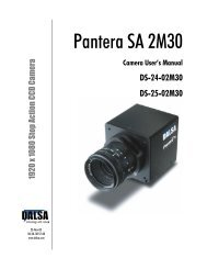
1.6k x 1.2k Stop Action Area Scan CCD Camera<br />
<strong>Pantera</strong> <strong>SA</strong> <strong>2M30</strong><br />
Camera User’s Manual<br />
DS-21-0<strong>2M30</strong><br />
DS-22-0<strong>2M30</strong><br />
23-Nov-05<br />
03-32-10150-01<br />
www.dalsa.com
<strong>Pantera</strong> <strong>SA</strong> DS -21-0<strong>2M30</strong> and DS-22-0<strong>2M30</strong> User’s Manual 2<br />
© 2005 DAL<strong>SA</strong>. All information provided in this manual is believed to be accurate and reliable. No<br />
responsibility is assumed by DAL<strong>SA</strong> for its use. DAL<strong>SA</strong> reserves the right to make changes to this<br />
information without notice. Reproduction of this manual in whole or in part, by any means, is prohibited<br />
without prior permission having been obtained from DAL<strong>SA</strong>.<br />
About DAL<strong>SA</strong><br />
DAL<strong>SA</strong> is an international high performance semiconductor and electronics company that designs,<br />
develops, manufactures, and markets digital imaging products and solutions, in addition to providing<br />
wafer foundry services. DAL<strong>SA</strong>’s core competencies are in specialized integrated circuit and electronics<br />
technology, and highly engineered semiconductor wafer processing. Products include image sensor<br />
components; electronic digital cameras; and semiconductor wafer foundry services for use in MEMS,<br />
power semiconductors, image sensors and mixed signal CMOS chips.<br />
DAL<strong>SA</strong> is a public company listed on the Toronto Stock Exchange under the symbol “D<strong>SA</strong>”. Based in<br />
Waterloo, On. Canada, the company has operations in Bromont, PQ; Colorado Springs, CO; Eindhoven,<br />
NL; Munich, Germany and Tokyo, Japan.<br />
All DAL<strong>SA</strong> products are manufactured using the latest state-of-the-art equipment to ensure product<br />
reliability. All electronic modules and cameras are subjected to a 24 hour burn-in test.<br />
For further information not included in this manual, or for information on DAL<strong>SA</strong>’s extensive line of<br />
image sensing products, please call:<br />
DAL<strong>SA</strong> Sales Offices<br />
Waterloo Europe Asia Pacific<br />
605 McMurray Rd<br />
Waterloo, ON N2V 2E9<br />
Canada<br />
Tel: 519 886 6000<br />
Fax: 519 886 8023<br />
www.dalsa.com<br />
sales.americas@dalsa.com<br />
Breslauer Str. 34<br />
D-82194 Gröbenzell (Munich)<br />
Germany<br />
Tel: +49 - 8142 – 46770<br />
Fax: +49 - 8142 – 467746<br />
www.dalsa.com<br />
sales.europe@dalsa.com<br />
Space G1 Building, 4F<br />
2-40-2 Ikebukuro<br />
Toshima-ku, Tokyo 171-0014<br />
Japan<br />
+81 3 5960 6353 (phone)<br />
+81 3 5960 6354 (fax)<br />
www.dalsa.com<br />
sales.asia@dalsa.com<br />
DAL<strong>SA</strong> Worldwide Operations<br />
Waterloo Colorado Springs Europe Asia Pacific<br />
605 McMurray Rd<br />
Waterloo, ON N2V 2E9<br />
Canada<br />
Tel: 519 886 6000<br />
Fax: 519 886 8023<br />
www.dalsa.com<br />
sales.americas@dalsa.com<br />
4820 Centennial Blvd., Suite<br />
115<br />
Colorado Springs, CO 80919<br />
U<strong>SA</strong><br />
Tel: 719 599 7700<br />
Fax: 719 599 7775<br />
www.dalsa.com<br />
sales.americas@dalsa.com<br />
Breslauer Str. 34<br />
D-82194 Gröbenzell (Munich)<br />
Germany<br />
Tel: +49 - 8142 – 46770<br />
Fax: +49 - 8142 – 467746<br />
www.dalsa.com<br />
sales.europe@dalsa.com<br />
Space G1 Building, 4F<br />
2-40-2 Ikebukuro<br />
Toshima-ku, Tokyo 171-0014<br />
Japan<br />
+81 3 5960 6353 (phone)<br />
+81 3 5960 6354 (fax)<br />
www.dalsa.com<br />
sales.asia@dalsa.com<br />
Camera Link is a trademark registered by PULNiX America Inc., as chair of a committee of industry<br />
members including DAL<strong>SA</strong>.<br />
DAL<strong>SA</strong> 03-32-10150-01
<strong>Pantera</strong> <strong>SA</strong> DS -21-0<strong>2M30</strong> and DS-22-0<strong>2M30</strong> User’s Manual 3<br />
Contents<br />
Introduction to the <strong>Pantera</strong> <strong>SA</strong> Area Scan Cameras ________________________________ 5<br />
1.1 Camera Highlights.......................................................................................................................................................5<br />
1.2 Image Sensors .............................................................................................................................................................6<br />
1.3 Camera Performance Specifications.............................................................................................................................8<br />
Camera Hardware Interface________________________________________________ 13<br />
2.1 Installation Overview...................................................................................................................................................13<br />
2.2 Input/Output Connectors and LED ...............................................................................................................................14<br />
Software Interface: How to Control the Camera __________________________________ 19<br />
3.1 Overview ......................................................................................................................................................................19<br />
3.2 Communications Protocol Overview.............................................................................................................................20<br />
3.3 Command Format........................................................................................................................................................20<br />
3.4 Startup .........................................................................................................................................................................20<br />
3.5 Saving and Restoring Settings .....................................................................................................................................20<br />
3.6 Setting Baud Rate........................................................................................................................................................21<br />
3.7 Selecting the Output Mode...........................................................................................................................................21<br />
3.8 Setting <strong>Frame</strong> Rate, Exposure Time, and Exposure Mode ...........................................................................................22<br />
3.9 Increasing Sensitivity with Binning (DS-21-0<strong>2M30</strong> Only) ...........................................................................................28<br />
3.10 Defining an Area of Interest (AOI) ............................................................................................................................29<br />
3.11 Optimizing Offset Performance .................................................................................................................................34<br />
3.12 Setting Gains .............................................................................................................................................................34<br />
3.13 Generating Test Patterns ...........................................................................................................................................34<br />
3.14 Monitoring Tasks .......................................................................................................................................................35<br />
3.15 Rebooting the Camera...............................................................................................................................................35<br />
3.16 Setting the Pre-trigger...............................................................................................................................................36<br />
3.17 Setting the Video Mode..............................................................................................................................................36<br />
Optical, Mechanical, Thermal, and Handling Considerations _________________________ 39<br />
4.1 Mechanical Interface ....................................................................................................................................................39<br />
4.2 Optical Interface...........................................................................................................................................................41<br />
4.3 Compliance ..................................................................................................................................................................43<br />
Troubleshooting________________________________________________________ 45<br />
5.1 Common Solutions.......................................................................................................................................................45<br />
5.2 Troubleshooting Using the Serial Interface .................................................................................................................46<br />
DAL<strong>SA</strong> 03-32-10150-01
<strong>Pantera</strong> <strong>SA</strong> DS -21-0<strong>2M30</strong> and DS-22-0<strong>2M30</strong> User’s Manual 4<br />
5.3 Specific Solutions .........................................................................................................................................................47<br />
5.4 Product Support ...........................................................................................................................................................49<br />
Camera Link Reference, Timing, and Configuration Table _________________________ 51<br />
Communications Protocol _________________________________________________ 57<br />
B1 Protocol Overview.........................................................................................................................................................57<br />
B2 Protocol Features..........................................................................................................................................................57<br />
B3 Command Format.........................................................................................................................................................57<br />
B4 Networking Mode .........................................................................................................................................................57<br />
B5 Error Handling..............................................................................................................................................................60<br />
B6 Commands....................................................................................................................................................................61<br />
Tap Matching Using Look up Tables (LUTs) _____________________________________ 67<br />
C1 Using Factory Calibrated Input LUTs ............................................................................................................................67<br />
C2 Creating a Custom Input LUT........................................................................................................................................68<br />
C3 Using the Output LUTs..................................................................................................................................................75<br />
C4 All LUT Commands and Examples................................................................................................................................75<br />
EMC Declaration of Conformity _____________________________________________ 81<br />
Revision History ________________________________________________________ 83<br />
Index _______________________________________________________________ 85<br />
DAL<strong>SA</strong> 03-32-10150-01
<strong>Pantera</strong> <strong>SA</strong> DS -21-0<strong>2M30</strong> and DS-22-0<strong>2M30</strong> User’s Manual 5<br />
Introduction to the<br />
<strong>Pantera</strong> <strong>SA</strong> Area Scan<br />
Cameras<br />
1<br />
1.1 Camera Highlights<br />
Features<br />
• 2-megapixel resolution: 1600 x 1200 pixels, 7.4µm x 7.4µm size<br />
• <strong>Frame</strong> rates up to 34fps, or, if using an area of interest, up to 250fps<br />
• 2x40MHz data rate via Camera Link high speed serial interface<br />
• Electronic, global non-rolling shutter for “Stop Action” imaging<br />
• Programmable area of interest<br />
• Single 11V to 25V power supply<br />
• Binning (DS-21-0<strong>2M30</strong> only)<br />
• Robust and compact design<br />
• Color option (DS-22-0<strong>2M30</strong>)<br />
Programmability<br />
• Simple ASCII protocol controls gain, offset, frame rates, trigger mode, test pattern<br />
output, and camera diagnostics<br />
• Serial interface (ASCII, 9600 baud, adjustable to 19200, 57600, 115200), through<br />
Camera Link<br />
Usability<br />
• Programmable gains, offsets, output modes, area of interest, and camera controls<br />
• Single input supply (+11V to +25V)<br />
DAL<strong>SA</strong> 03-32-10150-01
<strong>Pantera</strong> <strong>SA</strong> DS -21-0<strong>2M30</strong> and DS-22-0<strong>2M30</strong> User’s Manual 6<br />
• Compliant with CE (DS-21-0<strong>2M30</strong>)<br />
Description<br />
The <strong>Pantera</strong> <strong>SA</strong> <strong>2M30</strong> is an exceptional area scan camera for electronics manufacturing<br />
inspection, robotics, industrial metrology, and traffic management. The camera uses a 2<br />
megapixel interline transfer CCD capable of running at up to 34 frames per second (fps),<br />
or, if using area of interest windowing, up to 250fps. It features electronic global<br />
shuttering for “Stop Action” (<strong>SA</strong>) imaging. These features allow for a large field of view,<br />
no smear effect, and high throughput.<br />
Programmable features and diagnostics are accessible through the Camera Link<br />
MDR26 connector.<br />
This camera's small body and robustness make it perfect for the wear and tear of<br />
industrial environments.<br />
Applications<br />
The <strong>Pantera</strong> <strong>SA</strong> <strong>2M30</strong> is ideal for applications requiring high speed, superior image<br />
quality, and high responsivity. Applications include:<br />
• Electronics manufacturing inspection<br />
• Robotics<br />
• Industrial metrology<br />
• Traffic management<br />
1.2 Image Sensors<br />
The <strong>Pantera</strong> <strong>SA</strong> <strong>2M30</strong> camera uses a high-performance, dual-output, megapixel interline<br />
transfer CCD with 7.4µm square pixels and microlenses.<br />
DAL<strong>SA</strong> 03-32-10150-01
<strong>Pantera</strong> <strong>SA</strong> DS -21-0<strong>2M30</strong> and DS-22-0<strong>2M30</strong> User’s Manual 7<br />
DS-21-0<strong>2M30</strong> Monochrome Sensor<br />
Figure 1: DS-21-0<strong>2M30</strong> Image Sensor<br />
(Tap 1)<br />
(Tap 2)<br />
As viewed from front of CCD<br />
DS-22-0<strong>2M30</strong> Color Image Sensor<br />
Figure 2: DS-22-0<strong>2M30</strong> Image Sensor<br />
4 Buffer Rows<br />
4 Buffer Columns<br />
1600 (H) x 1200 (V)<br />
Active Pixels<br />
4 Buffer Columns<br />
(Tap 1) Video L<br />
4 Dummy Pixels<br />
Pixel 1, 1<br />
4 Buffer Rows<br />
4 Dummy Pixels<br />
Video R (Tap 2)<br />
Dual Output<br />
As viewed from front of CCD<br />
Note: The <strong>Pantera</strong> <strong>SA</strong> <strong>2M30</strong> is designed to provide dual output only.<br />
DAL<strong>SA</strong> 03-32-10150-01
<strong>Pantera</strong> <strong>SA</strong> DS -21-0<strong>2M30</strong> and DS-22-0<strong>2M30</strong> User’s Manual 8<br />
Figure 3: Color Filter Array Pattern (Bayer Pattern)<br />
Vertical<br />
Register<br />
First Imaging<br />
Pixel<br />
Horizontal<br />
Register<br />
Sensor Characteristics<br />
See Figure 1and Figure 2 for the sensor’s layout, including empty, light-shielded, and<br />
buffer pixels<br />
While the sensor’s right tap gives mirrored output, by default the camera reformats this<br />
tap internally—you will not have to reverse the right tap in a framegrabber’s line buffer<br />
to reconstruct the image. The left half of the image is clocked out Video L (tap 1) and the<br />
right half of the image is clocked out Video R (tap 2). Each row consists of 4 empty pixels<br />
followed by 16 light shielded pixels followed by 804 photoactive pixels.<br />
Table 1: Cosmetic Specifications<br />
Type Definition Max.<br />
Number<br />
Major Defective<br />
Pixels<br />
Minor Defective<br />
Pixels<br />
Cluster<br />
Column<br />
A pixel whose signal deviates by more than 25mV<br />
from the mean value of all active pixels under dark<br />
field conditions or by more than 15% from the<br />
mean value of all active pixels under uniform<br />
illumination of 80% of saturation.<br />
A pixel whose signal deviates by more than 8mV<br />
from the mean value of all active pixels under dark<br />
field conditions.<br />
A group of 2 to 20 contiguous major defective<br />
pixels with a width no wider than 2 defective<br />
pixels.<br />
A group of more than 10 contiguous major<br />
defective pixels along a single column.<br />
1.3 Camera Performance Specifications<br />
Table 2: <strong>Pantera</strong> <strong>SA</strong> <strong>2M30</strong> Performance Specifications<br />
Physical Characteristics Units Notes<br />
Power Dissipation, typ W 7.4 at 24V<br />
6.5 at 12V<br />
Time to power up, typ sec. 15<br />
Data output format bits 8 or 10 user<br />
selectable<br />
Camera<br />
Link<br />
20<br />
200<br />
8<br />
0<br />
DAL<strong>SA</strong> 03-32-10150-01
<strong>Pantera</strong> <strong>SA</strong> DS -21-0<strong>2M30</strong> and DS-22-0<strong>2M30</strong> User’s Manual 9<br />
Physical Characteristics Units Notes<br />
Sensor Alignment<br />
x, y<br />
z<br />
z<br />
Parallelism/Tilt<br />
µm<br />
µm<br />
°<br />
µm<br />
±400<br />
±300<br />
±2.1<br />
<strong>Pantera</strong> <strong>SA</strong> DS -21-0<strong>2M30</strong> and DS-22-0<strong>2M30</strong> User’s Manual 10<br />
Figure 4: DS-21-0<strong>2M30</strong> Sensor Quantum Efficiency<br />
<strong>Pantera</strong> <strong>SA</strong> <strong>2M30</strong> Sensor Quantum Efficiency<br />
45<br />
40<br />
35<br />
30<br />
%<br />
E<br />
Q<br />
25<br />
20<br />
15<br />
10<br />
5<br />
300 400 500 600 700 800 900 1000<br />
Wavelength<br />
(nm)<br />
Figure 5: DS-22-0<strong>2M30</strong> Quantum Efficiency<br />
Absolute Quantum Efficiency<br />
0.50<br />
0.45<br />
0.40<br />
0.35<br />
0.30<br />
0.25<br />
0.20<br />
0.15<br />
0.10<br />
0.05<br />
Measured with<br />
glass<br />
0.00<br />
400 500 600 700 800 900 1000<br />
Wavelength (nm)<br />
Red Green Blue<br />
DAL<strong>SA</strong> 03-32-10150-01
<strong>Pantera</strong> <strong>SA</strong> DS -21-0<strong>2M30</strong> and DS-22-0<strong>2M30</strong> User’s Manual 11<br />
Figure 6: <strong>Pantera</strong> <strong>SA</strong> <strong>2M30</strong> Angular Dependence of QE<br />
Relative QE%<br />
<strong>2M30</strong>-<strong>SA</strong> Angular Dependence of QE<br />
100<br />
90<br />
Vertical<br />
80<br />
Horizontal<br />
70<br />
60<br />
50<br />
40<br />
30<br />
20<br />
10<br />
0<br />
0 5 10 15 20 25 30<br />
Angle of incident light (relative to sensor plane)<br />
Horizontal = angle varied in plane parallel to HCCD<br />
Vertical= angle varied in plane parallel to VCCD<br />
DAL<strong>SA</strong> 03-32-10150-01
<strong>Pantera</strong> <strong>SA</strong> DS -21-0<strong>2M30</strong> and DS-22-0<strong>2M30</strong> User’s Manual 12<br />
DAL<strong>SA</strong> 03-32-10150-01
<strong>Pantera</strong> <strong>SA</strong> DS -21-0<strong>2M30</strong> and DS-22-0<strong>2M30</strong> User’s Manual 13<br />
Camera Hardware<br />
Interface<br />
2<br />
2.1 Installation Overview<br />
When setting up your camera, you should take these steps:<br />
This installation<br />
overview assumes you<br />
have not installed any<br />
system components yet.<br />
1. Power down all equipment.<br />
2. Following the manufacturer’s instructions, install the frame grabber (if applicable). Be<br />
sure to observe all static precautions.<br />
3. Install any necessary imaging software.<br />
4. Connect camera body and/or front plate to heat sink. Refer to Thermal Management<br />
& Dark Current on page 41 for more information. IMPORTANT: Prior to operation of<br />
the <strong>Pantera</strong> <strong>SA</strong> <strong>2M30</strong>, refer to Section 4.1 Mechanical Interface, for information<br />
regarding Thermal Management and Dark Current.<br />
5. Before connecting power to the camera, test all power supplies. Ensure that all the<br />
correct voltages are present at the camera end of the power. Power supplies must<br />
meet the requirements defined in section 2.4.<br />
6. Inspect all cables and connectors prior to installation. Do not use damaged cables or<br />
connectors or the camera may be damaged.<br />
7. Connect Camera Link and power cables.<br />
8. After connecting cables, apply power to the camera.<br />
9. Check the diagnostic LED. See 2.2.1 LED Status Indicator for a description.<br />
You must also set up the other components of your system, including light sources,<br />
camera mounts, host computers, optics, encoders, and so on.<br />
DAL<strong>SA</strong> 03-32-10150-01
<strong>Pantera</strong> <strong>SA</strong> DS -21-0<strong>2M30</strong> and DS-22-0<strong>2M30</strong> User’s Manual 14<br />
2.2 Input/Output Connectors and LED<br />
The camera uses a:<br />
• Diagnostic LED for monitoring the camera. See LED Status Indicator in section 2.2.1<br />
LED Status Indicator for details.<br />
• High-density 26-pin MDR26 connector for Camera Link control signals, data signals,<br />
and serial communications. Refer to section 2.2.2 Camera Link Data Connector for<br />
details.<br />
• 6-pin Hirose connector for power. Refer to section 2.2.3 Power Connector for details.<br />
Figure 7: <strong>Pantera</strong> <strong>SA</strong> <strong>2M30</strong> Input and Output<br />
CameraLink<br />
Diagnostic LED<br />
+11V to +25V and Ground<br />
!<br />
WARNING: It is extremely important that you apply the appropriate voltages to your camera.<br />
Incorrect voltages will damage the camera. See section 2.4 for more details.<br />
2.2.1 LED Status Indicator<br />
The camera is equipped with a red/green LED used to display the operational status of<br />
the camera. The table below summarizes the operating states of the camera and the<br />
corresponding LED states.<br />
When more than one condition is active, the LED indicates the condition with the highest<br />
priority. Error and warning states are accompanied by corresponding messages further<br />
describing the current camera status.<br />
Table 3: Diagnostic LED<br />
Color of Status LED<br />
Flashing Green<br />
Solid Green<br />
Flashing Red<br />
Solid Red<br />
Meaning<br />
Camera Initialization<br />
Camera Ready<br />
Fatal Error<br />
Warning, such as firmware did not load or Voltage out of limit.<br />
DAL<strong>SA</strong> 03-32-10150-01
<strong>Pantera</strong> <strong>SA</strong> DS -21-0<strong>2M30</strong> and DS-22-0<strong>2M30</strong> User’s Manual 15<br />
2.2.2 Camera Link Data Connector<br />
The Camera Link interface is implemented as a Base Configuration in the <strong>Pantera</strong> <strong>SA</strong><br />
cameras. A Base Configuration uses 1 MDR26 connector and 1 Channel Link chip. The<br />
main characteristics of the Base Configuration are:<br />
• Ports supported: A, B, C<br />
• Serializer bit width: 28<br />
• Number of chips: 1<br />
• Number of MDR26 connectors: 1<br />
Figure 8: MDR26 Connector<br />
13<br />
MDR26 Female<br />
1<br />
26<br />
14<br />
Mating Part: 3M 334-31 ser ies<br />
Cable: 3M 14X 26-SZ LB-X X X -0LC* *<br />
Table 4: MDR26 Connector Reference (Base Configuration)<br />
Item Value Item Value<br />
Pinout BASE Pinout BASE<br />
1 Logic Gnd via 0 ohm resistor 14 Logic Gnd via 0 ohm resistor<br />
2 X0- 15 X0+<br />
3 X1- 16 X1+<br />
4 X2- 17 X2+<br />
5 Xclk- 18 Xclk+<br />
6 X3- 19 X3+<br />
7 SERTC+ 20 SERTC-<br />
8 SERTFG- 21 SERTFG+<br />
9 CC1- 22 CC1+<br />
10 CC2+ 23 CC2-<br />
11 CC3- 24 CC3+<br />
12 CC4+ 25 CC4-<br />
13 Logic Gnd via 0 ohm resistor 26 Logic Gnd via a 0 ohm resistor<br />
Notes:<br />
*Exterior Overshield is connected to the shells of the connectors on both ends.<br />
**3M part 14X26-SZLB-XXX-0LC is a complete cable assembly, including connectors.<br />
Unused pairs should be terminated in 100 ohms at both ends of the cable.<br />
DAL<strong>SA</strong> 03-32-10150-01
<strong>Pantera</strong> <strong>SA</strong> DS -21-0<strong>2M30</strong> and DS-22-0<strong>2M30</strong> User’s Manual 16<br />
Table 5: DAL<strong>SA</strong> Camera Control Configuration<br />
Signal Configuration<br />
CC1<br />
CC2<br />
CC3<br />
CC4<br />
EXSYNC<br />
Spare<br />
Spare<br />
Spare<br />
See Appendix B on page 57 for the complete DAL<strong>SA</strong> Camera Link configuration table,<br />
and refer to the DAL<strong>SA</strong> Web site, vfm.dalsa.com, for the official Camera Link documents.<br />
Input Signals, Camera Link<br />
i<br />
The camera accepts control inputs through the Camera Link MDR26F connector.<br />
The camera ships in internal sync, internal programmed integration (exposure mode 2).<br />
EXSYNC (Triggers Line Readout)<br />
<strong>Frame</strong> rate can be set internally using the serial interface. The external control signal<br />
EXSYNC is optional and enabled through the serial interface. This camera uses the falling<br />
edge of EXSYNC to trigger line readout. Section 3.8 Setting <strong>Frame</strong> Rate, Exposure Time,<br />
and Exposure Mode details how to set frame times, exposure times, and camera modes.<br />
Output Signals, Camera Link<br />
IMPORTANT:<br />
This camera’s data<br />
should be sampled on<br />
the rising edge of<br />
STROBE.<br />
These signals indicate when data is valid, allowing you to clock the data from the camera<br />
to your acquisition system. These signals are part of the Camera Link configuration and<br />
you should refer to the DAL<strong>SA</strong> Camera Link Implementation Road Map, available at<br />
http://vfm.dalsa.com/, for the standard location of these signals.<br />
<br />
Clocking Signal<br />
LVAL (high)<br />
DVAL (high)<br />
STROBE (rising edge)<br />
FVAL (high)<br />
Indicates<br />
Outputting valid line<br />
Valid data<br />
Valid data<br />
Outputting valid frame<br />
The camera internally digitizes 10 bits and outputs all 10 bits.<br />
For a Camera Link reference and timing definitions refer to Appendix A on page 51.<br />
2.2.3 Power Connector<br />
Figure 9: Hirose 6-pin Circular Male—Power Connector<br />
Hirose 6-pin Circular Male<br />
1 6<br />
2 5<br />
3 4<br />
Mat ing Par t: HIRO SE<br />
HR10A-7P-6S<br />
Table 6: Hirose Pin Description<br />
Pin Description Pin Description<br />
1 +11 to +25V 4 GND<br />
2 +11 to +25V 5 GND<br />
3 +11 to +25V 6 GND<br />
DAL<strong>SA</strong> 03-32-10150-01
<strong>Pantera</strong> <strong>SA</strong> DS -21-0<strong>2M30</strong> and DS-22-0<strong>2M30</strong> User’s Manual 17<br />
The camera requires a single voltage input (+11V to +25V). The camera meets all<br />
performance specifications using standard switching power supplies, although wellregulated<br />
linear supplies provide optimum performance.<br />
When setting up the camera’s power supplies follow these guidelines:<br />
• Protect the camera with a fast-blow fuse between power supply and camera.<br />
• Do not use the shield on a multi-conductor cable for ground.<br />
• Keep leads as short as possible to reduce voltage drop.<br />
• Use high-quality linear supplies to minimize noise.<br />
!<br />
Note: Performance specifications are not guaranteed if your power supply does not meet<br />
these requirements. See section 1.3 for power requirements.<br />
WARNING: It is extremely important that you apply the appropriate voltages to your camera. Incorrect voltages<br />
will damage the camera. Protect the camera with a fast-blow fuse between power supply and camera.<br />
DAL<strong>SA</strong> offers a power supply with attached 6’ power cable that meets the <strong>2M30</strong>’s<br />
requirements, but it should not be considered the only choice. Many high quality supplies<br />
are available from other vendors. DAL<strong>SA</strong> assumes no responsibility for the use of these<br />
supplies.<br />
Visit the www.dalsa.com Web site for a list of companies that make power supplies that<br />
meet the camera’s requirements. The companies listed should not be considered the only<br />
choices.<br />
DAL<strong>SA</strong> 03-32-10150-01
<strong>Pantera</strong> <strong>SA</strong> DS -21-0<strong>2M30</strong> and DS-22-0<strong>2M30</strong> User’s Manual 18<br />
DAL<strong>SA</strong> 03-32-10150-01
<strong>Pantera</strong> <strong>SA</strong> DS -21-0<strong>2M30</strong> and DS-22-0<strong>2M30</strong> User’s Manual 19<br />
Software Interface: How<br />
to Control the Camera<br />
3<br />
3.1 Overview<br />
i<br />
This section contains<br />
some of the more<br />
commonly used<br />
commands. See<br />
Communications Protocol<br />
on page 55 for the<br />
complete syntax and<br />
command reference<br />
(including command<br />
shortcuts) for the<br />
camera’s serial interface.<br />
All camera features can be controlled through the serial interface. The camera can also be<br />
used without the serial interface after it has been set up correctly. Functions available<br />
include:<br />
• Controlling basic camera functions such as gain and choice of sync signal source<br />
(internal or external)<br />
• Camera calibration<br />
• Measuring some internal temperature and voltages<br />
• Capturing video<br />
• Generating a test pattern for debugging<br />
• Setting an area of interest<br />
The serial interface uses a simple ASCII-based protocol. The complete protocol is<br />
described in the Communications Protocol on page 57.<br />
Online Help<br />
For quick help, the camera can return all available commands and parameters through<br />
the serial interface. To generate this list, send the command h to the camera.<br />
Retrieving Camera Settings<br />
To read current camera settings, send the command gcp.<br />
DAL<strong>SA</strong> 03-32-10150-01
<strong>Pantera</strong> <strong>SA</strong> DS -21-0<strong>2M30</strong> and DS-22-0<strong>2M30</strong> User’s Manual 20<br />
3.2 Communications Protocol Overview<br />
Serial Protocol Defaults:<br />
<br />
<br />
<br />
<br />
<br />
<br />
8 data bits<br />
1 stop bit<br />
No parity<br />
No flow control<br />
9.6Kbps<br />
Camera does not echo characters<br />
3.3 Command Format<br />
3.4 Startup<br />
When entering commands, remember that:<br />
<br />
<br />
<br />
<br />
A carriage return (CR) ends each command.<br />
Values in square brackets are optional.<br />
The camera will answer each command with either a carriage return and line<br />
feed followed by "OK >" or "Error x: Error Message >". The ">" is always the<br />
last character sent by the camera.<br />
The following parameter conventions are used:<br />
t = tap number<br />
i = integer value<br />
f = real number<br />
s = string<br />
[ ] = optional parameter<br />
When the camera is first started, it must perform several actions before it is ready for<br />
imaging. This startup routine takes approximately 15 seconds, and follows this sequence:<br />
1. Initializes the camera and all internal hardware.<br />
2. Loads the last settings saved to non-volatile memory.<br />
3. Restores user settings if previously saved, otherwise factory settings.<br />
4. Performs a memory test and voltage test and reports an error if any occurred.<br />
After this startup sequence has completed, the camera will return either the prompt<br />
"OK>" if no error occurred, or an error code if a problem has been discovered.<br />
3.5 Saving and Restoring Settings<br />
The camera provides a number of commands for restoring, storing, and saving settings.<br />
<br />
To restore the original factory settings, use the command rfs.<br />
DAL<strong>SA</strong> 03-32-10150-01
<strong>Pantera</strong> <strong>SA</strong> DS -21-0<strong>2M30</strong> and DS-22-0<strong>2M30</strong> User’s Manual 21<br />
<br />
<br />
To save all current user settings to EEROM, use the command wus. The camera will<br />
automatically restore the saved user settings when powered up.<br />
To restore the last saved user settings, use the command rus.<br />
Factory Settings User Settings /<br />
EEROM<br />
restore<br />
Current<br />
Session<br />
write / restore<br />
3.6 Setting Baud Rate<br />
To set the speed of the camera serial communication port, use the command:<br />
Syntax:<br />
Syntax Elements:<br />
sbr i<br />
i<br />
Baud rate. Available baud rates are: 9600 (Default), 19200, 57600,<br />
and 115200.<br />
Notes: Power-on rate is always 9600 baud.<br />
<br />
The rc (reset camera) command will not reset the camera to the<br />
power-on baud rate.<br />
Example: sbr 57600<br />
3.7 Selecting the Output Mode<br />
In the <strong>2M30</strong>, you can select either 8 or 10-bit output.<br />
To select the camera output mode, use the command:<br />
Syntax:<br />
Syntax Elements:<br />
sdm i<br />
i<br />
0 10- bit<br />
1 8-bit<br />
Notes: To obtain the current data mode, use the command gcp.<br />
Example: sdm 0<br />
DAL<strong>SA</strong> 03-32-10150-01
<strong>Pantera</strong> <strong>SA</strong> DS -21-0<strong>2M30</strong> and DS-22-0<strong>2M30</strong> User’s Manual 22<br />
3.8 Setting <strong>Frame</strong> Rate, Exposure Time, and<br />
Exposure Mode<br />
With five different exposure mode settings, the <strong>2M30</strong> delivers many possibilities for<br />
flexible camera timing. Table 7 outlines each of these five exposure modes, and is<br />
followed by a full explanation on how to set the camera’s frame rate and exposure time.<br />
Table 7: Overview of <strong>Pantera</strong> <strong>SA</strong> <strong>2M30</strong> Exposure Modes<br />
Programmable<br />
<strong>Frame</strong> Rate<br />
Programmable<br />
Exposure Time<br />
i<br />
Mode 2 is the default<br />
Mode SYNC Description<br />
2 Internal Yes Yes (Factory setting) Internal SYNC ,<br />
programmable frame time and exposure<br />
time using commands ssf and set.<br />
Note: The parameter being programmed<br />
(i.e. <strong>Frame</strong> rate or Exposure time) will be the<br />
driving factor so that when setting frame<br />
rate, exposure time will change to<br />
accommodate the new frame rate and visaversa.<br />
3 External No No External SYNC, maximum exposure time<br />
(no shuttering).<br />
4 External No No “Smart EXSYNC” Mode: external exposure<br />
time – high time of external signal is<br />
exposure time and 1/period is frame rate.<br />
6 External No Yes External SYNC, programmable exposure<br />
time. NOTICE: The user is responsible for<br />
not violating timing constraints for the<br />
external sync signal used in this mode.<br />
Overview: Setting <strong>Frame</strong> Time and Exposure Time<br />
The camera’s frame rate (synchronization) can be generated internally through software<br />
commands or input externally from a frame grabber/host system. To select how you<br />
want the camera’s frame rate to be generated:<br />
1. You must first set the camera mode using the sem command. Refer to section 3.8.1<br />
Setting the Exposure Modes for details.<br />
2. Then, when applicable, use the commands ssf (mode 2 only) to set the frame rate<br />
and/or set (mode 2 or 6), to set the exposure time. Refer to Step Two on page 26 for<br />
details.<br />
DAL<strong>SA</strong> 03-32-10150-01
<strong>Pantera</strong> <strong>SA</strong> DS -21-0<strong>2M30</strong> and DS-22-0<strong>2M30</strong> User’s Manual 23<br />
3.8.1 Setting the Exposure Modes<br />
To set the camera exposure mode, use the command:<br />
Syntax:<br />
Syntax Elements:<br />
sem i<br />
i<br />
Exposure mode to use. Factory setting is 2.<br />
Notes: Refer to Table 7 for a quick list of available modes or to the following<br />
sections for a more detailed explanation.<br />
<br />
To obtain the current value of the exposure mode, use the command<br />
gcp.<br />
Related Commands:<br />
ssf, set<br />
Example: sem 3<br />
Mode 2: Internally Programmable <strong>Frame</strong> Rate and<br />
Exposure Time (Default)<br />
The parameter being programmed (i.e. frame rate or exposure time) will be the driving<br />
factor so that when setting frame rate, exposure time will change to accommodate the<br />
new frame rate and visa-versa. If you are using an area of interest while operating in<br />
mode 2, see section 3.10 Defining an Area of Interest (AOI) for more timing information.<br />
Note: If the frame period (the period needed to readout one frame) is less than the<br />
exposure time entered, the frame period will be set by the exposure time. The camera will<br />
use electronic shuttering when the exposure time is less than the frame period.<br />
Example 1: Exposure Time less than <strong>Frame</strong> Period<br />
Electronic<br />
Shutter<br />
Data<br />
Transfer<br />
Electronic<br />
Shutter<br />
Data<br />
Transfer<br />
Exposure Time<br />
Exposure Time<br />
Programmable Period<br />
Readout<br />
Readout<br />
<strong>Frame</strong> Period<br />
<strong>Frame</strong> Period<br />
Programmable Period<br />
DAL<strong>SA</strong> 03-32-10150-01
<strong>Pantera</strong> <strong>SA</strong> DS -21-0<strong>2M30</strong> and DS-22-0<strong>2M30</strong> User’s Manual 24<br />
Mode 3: External Trigger with Maximum Exposure<br />
<strong>Frame</strong> rate is set by the period of the external trigger pulses. Since there is no electronic<br />
shuttering, any trigger pulses faster than the readout time are ignored. The falling edge of<br />
the external trigger marks the beginning of the exposure.<br />
Example 2: <strong>Frame</strong> Rate is set by External Trigger Pulses.<br />
Data<br />
Transfer<br />
Data<br />
Transfer<br />
Exposure Time<br />
Readout<br />
Exposure Time<br />
Readout<br />
<strong>Frame</strong> Period<br />
<strong>Frame</strong> Period<br />
Trigger<br />
Ignored<br />
Trigger<br />
Trigger<br />
Mode 4: Smart EXSYNC, External <strong>Frame</strong> Rate and<br />
Exposure Time<br />
In this mode, the external trigger rate sets both the frame rate and the exposure time. The<br />
rising pulse of the external trigger marks the beginning of the exposure.<br />
Note: At the end of the exposure time, the collected data will be transferred to the read<br />
out area only if it is not already in the process of reading out. If readout is already in<br />
process, the exposure time will be extended until the readout has finished, as is illustrated<br />
in Example 4.<br />
Example 3: Trigger Period is Repetitive and Greater than Readout Time.<br />
Electronic<br />
Shutter<br />
Data<br />
Transfer<br />
Electronic<br />
Shutter<br />
Data<br />
Transfer<br />
Exposure Time<br />
Readout<br />
<strong>Frame</strong> Period<br />
Exposure Time<br />
Readout<br />
<strong>Frame</strong> Time<br />
Trigger<br />
DAL<strong>SA</strong> 03-32-10150-01
<strong>Pantera</strong> <strong>SA</strong> DS -21-0<strong>2M30</strong> and DS-22-0<strong>2M30</strong> User’s Manual 25<br />
Example 4: Trigger Period is Intermittent and Occasionally Shorter than Readout Time.<br />
Electronic<br />
Shutter<br />
Data<br />
Transfer<br />
Electronic<br />
Shutter<br />
Data<br />
Transfer<br />
Exposure Time<br />
Exposure Time<br />
Readout<br />
Exposure time has been extended to<br />
correspond with readout time and does not<br />
follow the falling trigger pulse.<br />
Trigger<br />
Mode 6: External <strong>Frame</strong> Rate and Internal Exposure<br />
Time<br />
This mode differs according to the trigger rate and the exposure time setting. However,<br />
the following rules apply to any condition:<br />
• Any additional external triggers occurring during the exposure time will be ignored.<br />
• All non-ignored external triggers will pulse an electronic shutter to dump any current<br />
exposure data at the start of the trigger pulse and start the exposure time.<br />
• At the end of the exposure time, the collected data will be transferred to the readout<br />
area only if it is not already in the process of reading out. If readout is already in<br />
process, the exposure time will be extended until the readout is finished, as is<br />
illustrated in Example 6.<br />
• If you are using an area of interest while operating in mode 6, see section 3.10<br />
Defining an Area of Interest (AOI) for more timing information.<br />
Example 5: Trigger Period is Repetitive and Greater than Readout Time<br />
Electronic<br />
Shutter<br />
Data<br />
Transfer<br />
Electronic<br />
Shutter<br />
Readout<br />
Exposure Time<br />
Programmable Period<br />
Exposure Time<br />
Readout<br />
External<br />
Trigger<br />
External<br />
Trigger<br />
DAL<strong>SA</strong> 03-32-10150-01
<strong>Pantera</strong> <strong>SA</strong> DS -21-0<strong>2M30</strong> and DS-22-0<strong>2M30</strong> User’s Manual 26<br />
Example 6: Trigger period is Nonreptitive and Occasionally Shorter than Readout Time<br />
Electronic<br />
Shutter<br />
Data<br />
Transfer<br />
Electronic<br />
Shutter<br />
Data<br />
Transfer<br />
Exposure Time<br />
Programmable Period<br />
Exposure Time<br />
Readout<br />
Exposure time has been extended to<br />
correspond with read out time.<br />
External<br />
Trigger<br />
External<br />
Trigger<br />
Ignored Ignored<br />
Trigger Trigger<br />
3.8.2 Setting <strong>Frame</strong> Rate and Exposure Time<br />
Setting <strong>Frame</strong> Rate<br />
Camera must be operating in exposure mode 2.<br />
To set the frame rate, use the command:<br />
Syntax:<br />
Syntax Elements:<br />
ssf i<br />
i<br />
Desired frame rate in Hz. Allowable ranges depend on binning mode<br />
and size of area of interest.<br />
Notes: To read the current frame rate frequency, use the command gcp.<br />
<br />
If you enter an invalid frame rate frequency, the valid range of<br />
values will be displayed.<br />
Related Commands:<br />
sem, set<br />
Example: ssf 50<br />
Setting Exposure Time<br />
Camera must be operating in exposure mode 2 or mode 6.<br />
Figure 10: Exposure Mode Time Ranges<br />
Mode Exposure Time Range<br />
2 Fixed by ssf command<br />
6 Limited by current frame rate (EXSYNC frequency)<br />
DAL<strong>SA</strong> 03-32-10150-01
<strong>Pantera</strong> <strong>SA</strong> DS -21-0<strong>2M30</strong> and DS-22-0<strong>2M30</strong> User’s Manual 27<br />
To set the camera exposure time, use the command:<br />
Syntax:<br />
set i<br />
Syntax Elements: i<br />
Integer number in µsecs. Allowable range is 41 – 1000000 µsecs.<br />
Notes: To read the current exposure time, use the command gcp.<br />
<br />
If you enter an invalid exposure time, the valid range of values will<br />
be displayed.<br />
Related Commands:<br />
sem, ssf<br />
Example: set 5500<br />
Shutter/Exposure Timing<br />
Because the <strong>Pantera</strong> <strong>SA</strong> <strong>2M30</strong> can be reading out a previous image while shuttering for<br />
the next image, there are some timing constrains imposed by the sensor specification on<br />
this timing. The result is that the actual frame time of the camera must be synchronized to<br />
the vertical clocking. The vertical clocks have a period of about 26µs so this produces an<br />
uncertainty window around the desired integration time to what is generated by the<br />
camera. The desired integration setting is accurate to +/- 1µs. The figure below shows<br />
how this uncertainty window is applied for various operating conditions.<br />
Figure 11: Integration Time Programming<br />
Vertical<br />
Clock<br />
line readout<br />
set by sensor spec<br />
26 µs Transfer<br />
Externa/Internall<br />
Trigger<br />
Electronic Shutter<br />
Uncertainty<br />
Window<br />
30 µs<br />
True Integration Time<br />
Internally programmed<br />
integration time.<br />
Desired Integration Time<br />
Uncertainty ± 1 µs<br />
Window<br />
DAL<strong>SA</strong> 03-32-10150-01
<strong>Pantera</strong> <strong>SA</strong> DS -21-0<strong>2M30</strong> and DS-22-0<strong>2M30</strong> User’s Manual 28<br />
3.9 Increasing Sensitivity with Binning (DS-21-<br />
0<strong>2M30</strong> Only)<br />
Binning increases the camera’s light sensitivity by decreasing horizontal and vertical<br />
resolution—the charge collected by adjacent pixels is added together.<br />
To set the binning value, use the command:<br />
Syntax:<br />
Syntax Elements:<br />
sbm i i<br />
i<br />
Horizontal binning value. Must be identical to the vertical binning value.<br />
i<br />
Vertical binning value. Must be identical to the horizontal binning value.<br />
Notes: Available values are 1x1 (factory setting), 2x2, or 4x4.<br />
To return to 1x1 mode (binning disabled), use the command sbm 1 1.<br />
<br />
Binning is recommended for the monochrome (DS-21-0<strong>2M30</strong>) <strong>2M30</strong><br />
only. Using binning with the color (DS-22-0<strong>2M30</strong>) <strong>2M30</strong> will cause<br />
invalid pixel summations.<br />
Example: sbm 2 2<br />
Figure 12: 2x2 Binning<br />
More charge<br />
=<br />
brighter pixel<br />
q1<br />
q3<br />
q2<br />
q4<br />
q1<br />
+<br />
q2<br />
+<br />
q3<br />
+<br />
q4<br />
a<br />
a<br />
2<br />
Charge in<br />
4 adjacent pixels<br />
1<br />
Charge binned:<br />
1 pixel output<br />
Normal image<br />
Binned image<br />
Table 8: Binning vs Speed<br />
Binning Read out Time (mS) <strong>Frame</strong> Rate Data Rate (MHz)<br />
1x1 28.6 34 2x40<br />
2x2 16.2 52.9 2x20<br />
4x4 10.0 79.3 2x10<br />
DAL<strong>SA</strong> 03-32-10150-01
<strong>Pantera</strong> <strong>SA</strong> DS -21-0<strong>2M30</strong> and DS-22-0<strong>2M30</strong> User’s Manual 29<br />
3.10 Defining an Area of Interest (AOI)<br />
By default, <strong>2M30</strong> has an active pixel region of 1600 x 1200. However, using the area of<br />
interest command, you can specify a reduced subset of the image to be read out from the<br />
sensor. The unwanted data is dumped, resulting in an increased frame rate and a<br />
reduction in data volume.<br />
Calculating <strong>Frame</strong> Rate<br />
Use the following formula to calculate the camera’s frame rate:<br />
Maximum <strong>Frame</strong> Rate (fps)=1000000/[({#Active Lines/Binning Factor + 6} x Step Size) +<br />
(#Dumped Lines x 2.8) + 94]<br />
Where Step Size is:<br />
Binning Mode 1 x 1 2 x 2 4 x 4<br />
Step Size (µs) 23.9 27.0 33.4<br />
<strong>Frame</strong> Rate Calculation Example<br />
The frame rate for a camera using an area of interest of 200 lines and 1 x 1 binning is:<br />
= 1000000/[(206 x 25.8) + (1000 x 2.8) + 94]<br />
= 1000000/[5314.8 + 2800 + 94]<br />
= 121.8<br />
Area of Interest Example<br />
In the example in Figure 13, an area of interest is set to capture 600 lines of image data—<br />
the remaining 600 lines are dumped through the sensor’s fast dump gate. The area of<br />
interest begins at line 301 and ends at line 900. The command syntax for this example is<br />
wse 0 0 1 301 1 900<br />
DAL<strong>SA</strong> 03-32-10150-01
<strong>Pantera</strong> <strong>SA</strong> DS -21-0<strong>2M30</strong> and DS-22-0<strong>2M30</strong> User’s Manual 30<br />
Figure 13: Area of Interest Example<br />
1200<br />
1600<br />
Dumped Lines<br />
900<br />
1200<br />
Area of interest set<br />
using the command:<br />
wse 0 0 1 301 1 900<br />
301<br />
1<br />
1<br />
Front view of 1600 x 1200 sensor<br />
1600<br />
Dumped Lines<br />
Figure 14: Area of Interest Example—Resulting Image<br />
1600<br />
600<br />
Resulting image<br />
read out from sensor<br />
DAL<strong>SA</strong> 03-32-10150-01
<strong>Pantera</strong> <strong>SA</strong> DS -21-0<strong>2M30</strong> and DS-22-0<strong>2M30</strong> User’s Manual 31<br />
Guidelines and Rules for Setting the AOI<br />
When setting the area of interest, be aware that:<br />
• Changing the area of interest settings while the camera is operating in mode 2 will<br />
also change the set or ssf settings. Always re-enter set and ssf values after<br />
changing the AOI while operating in mode 2. To check settings, enter the command<br />
gcp. The help screen will display one of the following sets of messages:<br />
Condition<br />
set and ssf settings are<br />
correct and camera is<br />
running in exposure mode 2<br />
set and ssf settings are<br />
incorrect and camera is<br />
running is exposure mode 2<br />
camera is running in<br />
exposure mode 3, 4, or 6<br />
Help Screen Message<br />
<strong>Frame</strong> Rate Settings within round off error: YES<br />
Exposure Time within round off error: YES<br />
<strong>Frame</strong> Rate Settings within round off error: NO.<br />
Re-enter ssf cmd<br />
Exposure Time within round off error: NO. Reenter<br />
set cmd<br />
<strong>Frame</strong> Rate Settings with round off error: NA<br />
Exposure Time within round off error: NA<br />
• Changing the AOI while operating the camera in mode 6 can result in an invalid set<br />
result. Always re-enter your set value after changing the AOI when operating in<br />
mode 6.<br />
• The camera will ignore any EXSYNC signals that occur quicker than the readout rate.<br />
• The exposure time setting cannot be greater than the frame time. The minimum<br />
frame time cannot be less than the readout time. If either of these conditions are<br />
violated, the camera will automatically adjust these settings.<br />
• If you are using binning, the window start/end values will be rounded using the<br />
following equations:<br />
Binning Start Value = INT [(Input Value-1)/Binning Factor] x Binning Factor +1<br />
Binning End Value = [INT {(Input Value-1)/Binning Factor} x Binning Factor +1]+<br />
(Binning Factor –1)<br />
• If you are using the color (DS-22-0<strong>2M30</strong>) <strong>2M30</strong>, the resolution of the color filter array<br />
Bayer Pattern (2x2) restricts the size and position of the AOI. You must specify an<br />
odd number for the start row and an even number for the end row. If you specify an<br />
even number for the start row, the Bayer pattern is reversed and the resulting image<br />
is corrupted.<br />
Timing Considerations<br />
When operating the camera in either exposure mode 2 or exposure mode 6, the camera<br />
timing may be altered.<br />
The electronic shutter cannot fire while the sensor is dumping unwanted data (regions 3<br />
and 5 in Figure 15). The electronic shutter will fire as soon as the dump is complete and<br />
the value set for the exposure time will be altered accordingly. You will not be told<br />
explicitly that the exposure time has been altered, but you can obtain the new value by<br />
entering the gcp command.<br />
DAL<strong>SA</strong> 03-32-10150-01
<strong>Pantera</strong> <strong>SA</strong> DS -21-0<strong>2M30</strong> and DS-22-0<strong>2M30</strong> User’s Manual 32<br />
Figure 15: Timing Considerations when using an Area of Interest<br />
REGION 2<br />
REGION 1<br />
READOUT ACTIVE<br />
FAST DUMP<br />
Electronic Shutter<br />
READOUT<br />
Ystart<br />
Yend<br />
Ymax<br />
region 5 region 4<br />
region 3<br />
dumped lines<br />
dumped lines<br />
note 2 note 1<br />
case D<br />
case C<br />
case B<br />
INTEGRATION TIME<br />
case A<br />
TRANSFER<br />
EXP_COUNTER<br />
start counter, count down<br />
hold<br />
0<br />
0<br />
WAIT COUNTER<br />
hold<br />
start counter, count down<br />
Note 1: If the shutter pulse is requested in region 3, it will be fired in region 1.<br />
Note 2: If the shutter pulse is requested in region 5, it will be fired in region 4.<br />
The new exposure time value depends on the AOI size and the frame rate. There are four<br />
different cases and are analyzed below (refer to Figure 15):<br />
Case A: Not affected by fast dump. The exposure time is set to the requested value.<br />
Case B: The exposure time requested requires that the electronic shutter be activated in<br />
region 3. The electronic shutter cannot be activated during the fast dump so the<br />
integration time will be reduced to the new value = <strong>Frame</strong> Time – Readout.<br />
Case C: The exposure time requested requires that the electronic shutter be activated in<br />
region 4. The electronic shutter will be fired in the same region and the exposure time<br />
is set to the entered value +/- the uncertainty error.<br />
Case D: The exposure time requested requires that the electronic shutter be activated in<br />
region 5. The electronic shutter cannot be activated during the fast dump so the<br />
integration time will be reduced to the value = <strong>Frame</strong> Time – Readout + Region 3 +<br />
Region 4.<br />
DAL<strong>SA</strong> 03-32-10150-01
<strong>Pantera</strong> <strong>SA</strong> DS -21-0<strong>2M30</strong> and DS-22-0<strong>2M30</strong> User’s Manual 33<br />
Setting the AOI<br />
To set the area of interest, use the command:<br />
Syntax:<br />
Syntax Elements:<br />
wse q i x1 y1 x2 y2<br />
q<br />
i<br />
x1<br />
y1<br />
x2<br />
y2<br />
Window sequence id to use. In the <strong>2M30</strong>, the sequence id is<br />
always 0.<br />
Window to set. In the <strong>2M30</strong>, the window id is always 0.<br />
The column start identifier with a range of 1 to the number<br />
of the horizontal pixels in the camera. Since the <strong>2M30</strong> only<br />
allows you to set a vertical area of interest, this value is<br />
always 1.<br />
The row start identifier with a range of 1 to an integer less<br />
than the row end identifier (y2). If you are using the color<br />
(DS-22-0<strong>2M30</strong>) <strong>2M30</strong>, this value must be odd in order to<br />
preserve the color filter array Bayer pattern. Otherwise, the<br />
image will be corrupted.<br />
The column end identifier with a range of 1 to the number<br />
of the horizontal pixels in the camera. Since the <strong>2M30</strong> only<br />
allows you to set a vertical area of interest, this value is<br />
always 1.<br />
The row end identifier with a range greater than the row<br />
start identifier (y1) to the number of vertical pixels in the<br />
sensor. If you are using the color (DS-22-0<strong>2M30</strong>) <strong>2M30</strong>, this<br />
value must be even in order to preserve the color filter array<br />
Bayer pattern. Otherwise, the image will be corrupted.<br />
Notes: Changing the AOI settings while in mode 2 or 6 will also<br />
change the set or ssf settings. See Guidelines and Rules<br />
for Setting the AOI on page 31 for more details.<br />
<br />
Also, changing the AOI settings while in modes 2 or 6 may<br />
alter camera timing. See Timing Considerations on page 31<br />
for more details.<br />
Example wse 0 0 1 301 1 900<br />
DAL<strong>SA</strong> 03-32-10150-01
<strong>Pantera</strong> <strong>SA</strong> DS -21-0<strong>2M30</strong> and DS-22-0<strong>2M30</strong> User’s Manual 34<br />
3.11 Optimizing Offset Performance<br />
Set the analog offset of the camera using the command:<br />
Syntax:<br />
Syntax Elements:<br />
sao t i<br />
t<br />
i<br />
Tap value. Use 0 for all taps or 1 to 2 for individual tap<br />
selection.<br />
Offset value. Allowable range is from 0 to 1023.<br />
Notes: The offset increases with higher values. The resulting analog<br />
offset value depends on other camera parameters such as<br />
temperature, frame rate, and gain but will fall somewhere<br />
between 1 and 10 DN.<br />
Example: sao 0 500<br />
3.12 Setting Gains<br />
To set the analog gain portion of the camera, use the command:<br />
Syntax:<br />
Syntax Elements:<br />
sg t f<br />
Example: sg 0 2.5<br />
3.13 Generating Test Patterns<br />
t<br />
f<br />
Tap value. Use 0 for all taps or 1 to 2 for individual tap<br />
selection.<br />
Gain setting. Allowable range is 0 to 15dB. For nominal gain,<br />
set to 0.<br />
The camera can generate a test pattern to aid in system debugging. The test pattern is a<br />
ramp from 25 to 824DN (on each channel), then starts at 25 again. Use the test pattern to<br />
verify the proper timing and connections between the camera and the frame grabber.<br />
To generate a test pattern, use the command:<br />
Syntax:<br />
Syntax Elements:<br />
svm i<br />
Example: svm 2<br />
i<br />
1 Test pattern left side<br />
2 Test pattern right side<br />
3 Test pattern both sides<br />
DAL<strong>SA</strong> 03-32-10150-01
<strong>Pantera</strong> <strong>SA</strong> DS -21-0<strong>2M30</strong> and DS-22-0<strong>2M30</strong> User’s Manual 35<br />
3.14 Monitoring Tasks<br />
Note: By default all<br />
monitoring tasks are<br />
enabled.<br />
The camera enters a warning state when any of camera's continuously running<br />
monitoring tasks detects a failure. Use the wed i i command to display the status of all<br />
the defined monitory tasks (if no parameter is passed) and/or to enable/disable specific<br />
monitoring tasks. Table 9 below lists the monitoring tasks.<br />
Table 9: <strong>Pantera</strong> <strong>SA</strong> <strong>2M30</strong> Monitoring Tasks<br />
Command Monitoring Task Description<br />
wed All Display the status of all monitoring tasks<br />
wed 0 0<br />
wed 0 1<br />
wed 1 0<br />
wed 1 1<br />
wed 2 0<br />
wed 2 1<br />
All<br />
Voltage<br />
Gain out of spec<br />
Disables all monitoring tasks.<br />
Enables all monitoring tasks.<br />
Monitors all camera voltages.<br />
Disables monitoring of camera voltages.<br />
Monitors current setting of analog gain.<br />
Disables monitoring of analog gain setting.<br />
Example:<br />
To enable all monitoring tasks:<br />
wed 0 1<br />
Voltage Measurement<br />
The command vv checks some of the camera’s input voltage and internal voltages during<br />
power-up. If they are within the proper range, the camera returns OK>. Otherwise the<br />
camera returns an error message. Note that the voltage measurement feature of the<br />
camera provides only approximate results (typically within 10%). They should not be<br />
used to set the applied voltage to the camera. The purpose of this test is to isolate gross<br />
problems with the supply voltages.<br />
3.15 Rebooting the Camera<br />
The command rc reboots the camera. The camera starts up with the last saved settings.<br />
DAL<strong>SA</strong> 03-32-10150-01
<strong>Pantera</strong> <strong>SA</strong> DS -21-0<strong>2M30</strong> and DS-22-0<strong>2M30</strong> User’s Manual 36<br />
3.16 Setting the Pre-trigger<br />
A pre-trigger may be required for some frame grabbers.<br />
To set the pre-trigger, use the command:<br />
Syntax:<br />
Syntax Elements:<br />
sp i<br />
i<br />
Pretrigger value from 0 to 15.<br />
Example: sp 10<br />
3.17 Setting the Video Mode<br />
To set the video mode, use the command:<br />
Syntax:<br />
Syntax Elements:<br />
svm i<br />
i<br />
Video mode to use. See table below for a description of<br />
available modes.<br />
Table 10: <strong>Pantera</strong> <strong>SA</strong> <strong>2M30</strong> Video Modes<br />
Mode Description Example Image<br />
0 Normal operating mode<br />
A<br />
W<br />
1 Test pattern left side<br />
2 Test pattern right side<br />
3 Test pattern both sides<br />
4 Flip image left side<br />
5 Flip image left side. Test pattern left side<br />
6 Flip image left side. Test pattern right side<br />
7 Flip image left side. Test pattern both sides<br />
8 Flip image right side<br />
A<br />
W<br />
9 Flip image right side. Test pattern left side<br />
10 Flip image right side. Test pattern right side<br />
DAL<strong>SA</strong> 03-32-10150-01
<strong>Pantera</strong> <strong>SA</strong> DS -21-0<strong>2M30</strong> and DS-22-0<strong>2M30</strong> User’s Manual 37<br />
Mode Description Example Image<br />
11 Flip image right side. Test pattern both sides<br />
12 Flip image both sides<br />
13 Flip image both sides. Test pattern left side<br />
14 Flip image both sides. Test pattern right side<br />
15 Flip image both sides. Test pattern both<br />
sides<br />
DAL<strong>SA</strong> 03-32-10150-01
<strong>Pantera</strong> <strong>SA</strong> DS -21-0<strong>2M30</strong> and DS-22-0<strong>2M30</strong> User’s Manual 38<br />
DAL<strong>SA</strong> 03-32-10150-01
<strong>Pantera</strong> <strong>SA</strong> DS -21-0<strong>2M30</strong> and DS-22-0<strong>2M30</strong> User’s Manual 39<br />
Optical, Mechanical,<br />
Thermal, and Handling<br />
Considerations<br />
4<br />
4.1 Mechanical Interface<br />
Mounting<br />
The camera can be mounted using the M3 holes (metric-threaded) on its base or top, and<br />
on its front plate at the corners.<br />
Environment<br />
The camera and cables should be shielded from environmental noise sources for best<br />
operation. The camera should also be kept as cool as possible. The specified operating<br />
temperature is 10–40°C measured at the bottom plate. Mounting holes (refer above) allow<br />
you to attach the necessary heat sinking.<br />
DAL<strong>SA</strong> 03-32-10150-01
<strong>Pantera</strong> <strong>SA</strong> DS -21-0<strong>2M30</strong> and DS-22-0<strong>2M30</strong> User’s Manual 40<br />
Figure 16: Mechanical Interface<br />
M3x.5 x 3.5 DEEP<br />
3 PLACES (FOR<br />
DAL<strong>SA</strong> ACCESSORIES)<br />
37.50<br />
8.7<br />
15.9<br />
11.5<br />
49.6<br />
17.6<br />
9.5<br />
2.8<br />
M3x.5 x 6 DEEP<br />
4x<br />
37.0<br />
27.99±.40<br />
22.00±.40<br />
M42x1 x 5 DEEP<br />
M3x.5 x 6 DEEP<br />
4 PLACES<br />
62.6<br />
56.5<br />
6.56±.30<br />
OPTICAL<br />
DISTANCE<br />
IMAGE PLANE<br />
PARALLEL TO FRONT<br />
SURFACE:
<strong>Pantera</strong> <strong>SA</strong> DS -21-0<strong>2M30</strong> and DS-22-0<strong>2M30</strong> User’s Manual 41<br />
Thermal Management & Dark Current<br />
For any CCD camera optimal performance is achieved by transferring heat away from the<br />
sensor. Keeping a sensor “cool” reduces the amount of dark current generated. Dark<br />
current is the leading contributor to FPN, PRNU, dark offset, random noise and other<br />
performance specifications, especially when a camera is significantly gained (i.e. +10db).<br />
Generally, dark current doubles for every 7°C increase in temperature at the sensor and<br />
increases linearly with integration time.<br />
The <strong>Pantera</strong> <strong>SA</strong> <strong>2M30</strong> has been optimized to transfer heat from the sensor to the front and<br />
base plates. Therefore, to reduce dark current, the front and base plates are the ideal<br />
places to mount heat sinks.<br />
Some suggestions for optimizing camera cooling are:<br />
• To minimize power dissipation, keep input voltage as low as possible in the<br />
permitted 11 to 25V range.<br />
• Always operate the camera with a lens adapter or lens. The lens transfers a significant<br />
amount of heat from the interior of the camera, effectively acting as a heat sink.<br />
• Clamping a metal plate to the base of the camera. Keep in mind that the thicker and<br />
wider the metal plate, the more effective the cooling.<br />
• Convection is an ideal method to minimize camera warm-up times and reduce dark<br />
current generation. Mount fans away from the camera to avoid vibration, and direct<br />
the airflow across the housing to decrease the temperature delta between ambient<br />
and bottom plate temperatures.<br />
DAL<strong>SA</strong> also offers a custom <strong>Pantera</strong> <strong>SA</strong> <strong>2M30</strong> heat sink, which can be purchased as a<br />
non-standard accessory (contact DAL<strong>SA</strong> for more information).<br />
4.2 Optical Interface<br />
Depending upon resolution the cameras can be ordered with different lens mounts. The<br />
following table provides this information.<br />
Lens Mounts<br />
All C-mount and F-mount adapters have the appropriate back focal distance for the lens<br />
type being used. Ensure that the image circle diameter of the lens to be used is as great as<br />
the length of the imaging region. The following table provides information regarding the<br />
lens mount used and the back focal distance. The M42 lens adapter originated from the<br />
high-end photography standard. Distances to its inner flat surface and the outer flat<br />
surface are provided.<br />
Table 11: Lens Mounts<br />
Mount Back Focal Distance (sensor die to adapter)<br />
C-Mount<br />
F-Mount<br />
M42<br />
17.52 ±0.30mm<br />
46.5 ±0.30mm<br />
6.56mm ±0.30mm—outer flat surface<br />
DAL<strong>SA</strong> 03-32-10150-01
<strong>Pantera</strong> <strong>SA</strong> DS -21-0<strong>2M30</strong> and DS-22-0<strong>2M30</strong> User’s Manual 42<br />
Illumination<br />
The amount and wavelengths of light required to capture useful images depend on the<br />
particular application. Factors include the nature, speed, and spectral characteristics of<br />
objects being imaged, exposure times, light source characteristics, environmental and<br />
acquisition system specifics, and more. DAL<strong>SA</strong>’s web site, http://vfm.dalsa.com/,<br />
provides an introduction to this potentially complicated issue. See “Radiometry and<br />
Photo Responsivity” and "Sensitivities in Photometric Units" in the CCD Technology<br />
Primer found under the Application Support link.<br />
It is often more important to consider exposure than illumination. The total amount of<br />
energy (which is related to the total number of photons reaching the sensor) is more<br />
important than the rate at which it arrives. For example, 5J/cm 2 can be achieved by<br />
exposing 5mW/cm 2 for 1ms just the same as exposing an intensity of 5W/cm 2 for 1s.<br />
Light Sources<br />
Keep these guidelines in mind when setting up your light source:<br />
• LED light sources are relatively inexpensive, provide a uniform field, and longer life<br />
span compared to other light sources. However, they also require a camera with<br />
excellent sensitivity, such as DAL<strong>SA</strong>’s <strong>2M30</strong> camera.<br />
• Halogen light sources generally provide very little blue relative to IR.<br />
• Fiber-optic light distribution systems generally transmit very little blue relative to IR.<br />
• Some light sources age; over their life span they produce less light. This aging may<br />
not be uniform—a light source may produce progressively less light in some areas of<br />
the spectrum but not others.<br />
Filters<br />
CCD cameras are extremely responsive to infrared (IR) wavelengths of light. To prevent<br />
infrared from distorting the images you scan, use a “hot mirror” or IR cutoff filter that<br />
transmits visible wavelengths but does not transmit wavelengths over 750nm. Examples<br />
are the Schneider Optics B+W 489, which includes a mounting ring, the CORION LS-<br />
750, which does not include a mounting ring, and the CORION HR-750 series hot<br />
mirror.<br />
Lens Modeling<br />
Any lens surrounded by air can be modeled for camera purposes using three primary<br />
points: the first and second principal points and the second focal point. The primary<br />
points for a lens should be available from the lens data sheet or from the lens<br />
manufacturer. Primed quantities denote characteristics of the image side of the lens. That<br />
is, h is the object height and h is the image height.<br />
The focal point is the point at which the image of an infinitely distant object is brought to<br />
focus. The effective focal length (f) is the distance from the second principal point to the<br />
second focal point. The back focal length (BFL) is the distance from the image side of the<br />
lens surface to the second focal point. The object distance (OD) is the distance from the first<br />
principal point to the object.<br />
DAL<strong>SA</strong> 03-32-10150-01
<strong>Pantera</strong> <strong>SA</strong> DS -21-0<strong>2M30</strong> and DS-22-0<strong>2M30</strong> User’s Manual 43<br />
Figure 17: Primary Points in a Lens System<br />
Magnification and Resolution<br />
The magnification of a lens is the ratio of the image size to the object size:<br />
m<br />
h where m is the magnification, h’ is the image height<br />
<br />
h (pixel size) and h is the object height (desired object<br />
resolution size).<br />
By similar triangles, the magnification is alternatively given by:<br />
f<br />
m <br />
OD<br />
These equations can be combined to give their most useful form:<br />
h f<br />
<br />
h OD<br />
This is the governing equation for many object and<br />
image plane parameters.<br />
4.3 Compliance<br />
Example: An acquisition system has a 512 x 512 element, 10m pixel pitch area scan<br />
camera, a lens with an effective focal length of 45mm, and requires that 100m in the<br />
object space correspond to each pixel in the image sensor. Using the preceding equation,<br />
the object distance must be 450mm (0.450m).<br />
10m<br />
45mm<br />
OD 450mm ( 0. 450m)<br />
100m<br />
OD<br />
The <strong>Pantera</strong> <strong>SA</strong> DS-21-0<strong>2M30</strong> and DS-22-0<strong>2M30</strong> camera has been designed for EMC<br />
compliance. The test setup has been verified to the following EMC standards:<br />
CISPR-22:1997<br />
EN 50082-1:1997<br />
EN 61000-4-2; ±6kV CD, ±8kV AD:1995<br />
EN 61000-4-3; 3V/m:1996<br />
EN 61000-4-4; 500V, 1100V:1995<br />
Follow these specific guidelines to ensure best performance:<br />
• Keep Camera Link cables as short as possible.<br />
• Ensure that all cable shields have 360 electrical connection to the connector.<br />
• Fasten and secure all connectors.<br />
DAL<strong>SA</strong> 03-32-10150-01
<strong>Pantera</strong> <strong>SA</strong> DS -21-0<strong>2M30</strong> and DS-22-0<strong>2M30</strong> User’s Manual 44<br />
DAL<strong>SA</strong> 03-32-10150-01
<strong>Pantera</strong> <strong>SA</strong> DS -21-0<strong>2M30</strong> and DS-22-0<strong>2M30</strong> User’s Manual 45<br />
Troubleshooting<br />
5<br />
The information in this chapter can help you solve problems that may occur during the<br />
setup of your camera. Remember that the camera is part of the entire acquisition system.<br />
You may have to troubleshoot any or all of the following:<br />
power supplies<br />
frame grabber hardware & software<br />
light sources<br />
operating environment<br />
cabling<br />
host computer<br />
optics<br />
encoder<br />
Your steps in dealing with a technical problem should be:<br />
1. Try the general and specific solutions listed in sections 5.1, 5.2, and 5.3.<br />
2. If these solutions do not resolve your problem, see section 5.4 on getting product<br />
support.<br />
5.1 Common Solutions<br />
Connections<br />
The first step in troubleshooting is to verify that your camera has all the correct<br />
connections.<br />
Power Supply Voltages<br />
Check for the presence of all voltages at the camera power connector. Verify that all<br />
grounds are connected.<br />
EXSYNC<br />
When the camera is powered on for the first time, it defaults to exposure mode 2. After a<br />
user has saved settings, the camera powers up with the saved settings. Note: A warning<br />
appears when switching to an exposure mode requiring external signals if external<br />
signals are not present (EXSYNC). For more information on setting exposure modes, refer<br />
to section 3.8 Setting <strong>Frame</strong> Rate, Exposure Time, and Exposure Mode.<br />
DAL<strong>SA</strong> 03-32-10150-01
<strong>Pantera</strong> <strong>SA</strong> DS -21-0<strong>2M30</strong> and DS-22-0<strong>2M30</strong> User’s Manual 46<br />
Data Clocking/Output Signals<br />
To validate cable integrity, have the camera send out a test pattern and verify it is being<br />
properly received. Refer to section 3.13 Generating Test Patterns for further information.<br />
5.2 Troubleshooting Using the Serial Interface<br />
The following commands can aid in debugging. (The complete command protocol is<br />
described in Appendix B.)<br />
Communications<br />
To quickly verify serial communications send the help command. The h command<br />
returns the online help menu.<br />
Verify Parameters<br />
To verify the camera setup, send the gcp command.<br />
Verify Factory Calibrated Settings<br />
To restore the camera’s factory settings send the rfs command.<br />
After executing this command send the gcp command to verify the factory settings.<br />
Verify Timing and Digital Video Path<br />
Use the test pattern feature to verify the proper timing and connections between the<br />
camera and the frame grabber and verify the proper output along the digital processing<br />
chain. See below.<br />
Generating Test Patterns<br />
The camera can generate a test pattern to aid in system debugging. Use the command<br />
svm 3 to activate the test pattern, both sides. The test pattern is a ramp from 25 to<br />
824DN, then starts at 0 again. Use the test pattern to verify the proper timing and<br />
connections between the camera and the frame grabber.<br />
<br />
<br />
No test pattern or bad test pattern — May indicate a problem with the camera (e.g.<br />
missing bit) or a system setup problem (e.g. frame grabber or timing). Verify the<br />
presence of the LVAL and STROBE signals.<br />
Test pattern successful— Run the svm 0 command to deactivate video correction.<br />
Adjust the analog offset using the sao commands. Under light conditions, you<br />
should receive a value.<br />
DAL<strong>SA</strong> 03-32-10150-01
<strong>Pantera</strong> <strong>SA</strong> DS -21-0<strong>2M30</strong> and DS-22-0<strong>2M30</strong> User’s Manual 47<br />
Verify Voltage<br />
To check the camera’s input voltages and internal voltages, use the vv command. If they<br />
are within the proper range, the camera returns OK>. Otherwise the camera returns an<br />
error message.<br />
LED Status<br />
Located on the back of the camera is a red/green LED used to display the operational<br />
status of the camera. Red lights indicate errors or warnings and green lights indicate<br />
progress and OKs. Error and warning states are accompanied by corresponding messages<br />
further describing current camera status. See section for the complete LED information.<br />
Monitoring Tasks<br />
The camera enters a warning state when any of the camera's continuously running<br />
monitoring tasks detects a failure. Use the wed command to display the status of all the<br />
defined monitory tasks (if no parameter is passed) and/or to enable/disable specific<br />
monitoring tasks. See section 3.14 Monitoring Tasks on page 35 for the complete<br />
Monitoring Tasks information.<br />
5.3 Specific Solutions<br />
No Output or Erratic Behavior<br />
If your camera provides no output or behaves erratically, it may be picking up random<br />
noise from long cables acting as antennae. Do not attach wires to unused pins. Verify that<br />
the camera is not receiving spurious inputs (e.g. EXSYNC, if camera is in exposure mode<br />
that regulates external signals).<br />
Line Dropout, Bright Lines, or Incorrect <strong>Frame</strong> rate<br />
Verify that the frequency of the internal sync is set correctly, or when the camera is set to<br />
external sync that the EXSYNC signal supplied to the camera does not exceed the<br />
camera’s maximum specified frame rate.<br />
Noisy Output<br />
Check your power supply voltage outputs for noise. Noise present on these lines can<br />
result in poor video quality. Low quality or non-twisted pair cable can also add noise to<br />
the video output.<br />
Dark Patches<br />
If dark patches appear in your output the optics path may have become contaminated.<br />
Clean your lenses and sensor windows with extreme care.<br />
1. Take standard ESD precautions.<br />
DAL<strong>SA</strong> 03-32-10150-01
<strong>Pantera</strong> <strong>SA</strong> DS -21-0<strong>2M30</strong> and DS-22-0<strong>2M30</strong> User’s Manual 48<br />
2. Wear latex gloves or finger cots<br />
3. Blow off dust using a filtered blow bottle or dry, filtered compressed air.<br />
4. Fold a piece of optical lens cleaning tissue (approx. 3" x 5") to make a square pad that<br />
is approximately one finger-width<br />
5. Moisten the pad on one edge with 2-3 drops of clean solvent—either alcohol or<br />
acetone. Do not saturate the entire pad with solvent.<br />
6. Wipe across the length of the window in one direction with the moistened end first,<br />
followed by the rest of the pad. The dry part of the pad should follow the moistened<br />
end. The goal is to prevent solvent from evaporating from the window surface, as<br />
this will end up leaving residue and streaking behind.<br />
7. Repeat steps 2-4 using a clean tissue until the entire window has been cleaned.<br />
8. Blow off any adhering fibers or particles using dry, filtered compressed air.<br />
Horizontal Lines or Patterns in Image<br />
A faulty or irregular encoder signal may result in horizontal lines due to exposure time<br />
fluctuations; ensure that your exposure time is regular. If you have verified that your<br />
exposure time is consistent and patterns of low frequency intensity variations still occur,<br />
ensure that you are using a DC or high frequency light source.<br />
Color Image is Corrupted when Using Binning<br />
and/or AOI<br />
If you are using binning:<br />
Invalid pixel summations will occur when you use binning with the color <strong>2M30</strong>. Disable<br />
binning using the command sbm 1 1.<br />
If you are using an AOI:<br />
You must preserve the color filter array pattern or the image will be corrupted. To<br />
preserve the color filter array pattern, ensure that the row start identifier (y1) is odd, and<br />
the row end (y2) identifier is even when setting the AOI with the wse command. See<br />
section 3.10 Defining an Area of Interest (AOI) for more information on setting the AOI.<br />
DAL<strong>SA</strong> 03-32-10150-01
<strong>Pantera</strong> <strong>SA</strong> DS -21-0<strong>2M30</strong> and DS-22-0<strong>2M30</strong> User’s Manual 49<br />
5.4 Product Support<br />
If there is a problem with your camera, collect the following data about your application<br />
and situation and call your DAL<strong>SA</strong> representative.<br />
Note: You may also want to photocopy this page to fax to DAL<strong>SA</strong>.<br />
Customer name<br />
Organization name<br />
Customer phone number<br />
fax number<br />
Complete Product Model Number<br />
(e.g. DS-21-0<strong>2M30</strong>...)<br />
Complete Serial Number<br />
Your DAL<strong>SA</strong> Agent or<br />
Dealer<br />
Acquisition System hardware<br />
(frame grabber, host computer,<br />
light sources, etc.)<br />
Acquisition System software<br />
(version, OS, etc.)<br />
Power supplies and current<br />
draw<br />
Data rate used<br />
Control signals used in your<br />
application, and their frequency<br />
or state (if applicable)<br />
Results when you run the<br />
gcp command<br />
Detailed description of<br />
problem encountered.<br />
EXSYNC<br />
MCLK<br />
BIN<br />
Other _______<br />
please attach description with as much detail as<br />
appropriate<br />
In addition to your local DAL<strong>SA</strong> representative, you may need to call DAL<strong>SA</strong> Technical<br />
Sales Support:<br />
Voice:<br />
Fax:<br />
North America<br />
519-886-6000<br />
519-886-8023<br />
Europe<br />
+49-8142-46770<br />
+49-8142-467746<br />
Asia<br />
519-886-6000<br />
519-886-8023<br />
DAL<strong>SA</strong> 03-32-10150-01
<strong>Pantera</strong> <strong>SA</strong> DS -21-0<strong>2M30</strong> and DS-22-0<strong>2M30</strong> User’s Manual 50<br />
DAL<strong>SA</strong> 03-32-10150-01
<strong>Pantera</strong> <strong>SA</strong> DS -21-0<strong>2M30</strong> and DS-22-0<strong>2M30</strong> User’s Manual 51<br />
Appendix A<br />
Camera Link Reference,<br />
Timing, and Configuration Table<br />
Camera Link is a communication interface for vision applications. It provides a<br />
connectivity standard between cameras and frame grabbers.<br />
LVDS Technical Description<br />
Low Voltage Differential Signaling (LVDS) is a high-speed, low-power general purpose<br />
interface standard. The standard, known as ANSI/TIA/EIA-644, was approved in March<br />
1996. LVDS uses differential signaling, with a nominal signal swing of 350mV differential.<br />
The low signal swing decreases rise and fall times to achieve a theoretical maximum<br />
transmission rate of 1.923 Gbps into a loss-less medium. The low signal swing also means<br />
that the standard is not dependent on a particular supply voltage. LVDS uses currentmode<br />
drivers, which limit power consumption. The differential signals are immune to ±1<br />
V common volt noise.<br />
Camera Signal Requirements<br />
This section provides definitions for the signals used in the Camera Link interface. The<br />
standard Camera Link cable provides camera control signals, serial communication, and<br />
video data.<br />
Video Data<br />
The Channel Link technology is integral to the transmission of video data. Image data<br />
and image enable signals are transmitted on the Channel Link bus. Four enable signals<br />
are defined as:<br />
• FVAL—<strong>Frame</strong> Valid (FVAL) is defined HIGH for valid lines.<br />
• LVAL—Line Valid (LVAL) is defined HIGH for valid pixels.<br />
• DVAL—Data Valid (DVAL) is defined HIGH when data is valid.<br />
• Spare— A spare has been defined for future use.<br />
All four enable signals must be provided by the camera on each Channel Link chip. All<br />
unused data bits must be tied to a known value by the camera. For more information on<br />
image data bit allocations, refer to the official Camera Link specification on the<br />
http://vfm.dalsa.com Web site.<br />
DAL<strong>SA</strong> 03-32-10150-01
<strong>Pantera</strong> <strong>SA</strong> DS -21-0<strong>2M30</strong> and DS-22-0<strong>2M30</strong> User’s Manual 52<br />
Camera Control Signals<br />
Four LVDS pairs are reserved for general-purpose camera control. They are defined as<br />
camera inputs and frame grabber outputs. Camera manufacturers can define these signals<br />
to meet their needs for a particular product. The signals are:<br />
• Camera Control 1 (CC1)<br />
• Camera Control 2 (CC2)<br />
• Camera Control 3 (CC3)<br />
• Camera Control 4 (CC4)<br />
Communication<br />
Two LVDS pairs have been allocated for asynchronous serial communication to and from<br />
the camera and frame grabber. Cameras and frame grabbers should support at least 9600<br />
baud. These signals are<br />
• SerTFG—Differential pair with serial communications to the frame grabber.<br />
• SerTC—Differential pair with serial communications to the camera.<br />
The serial interface will have the following characteristics: one start bit, one stop bit, no<br />
parity, and no handshaking. It is recommended that frame grabber manufacturers supply<br />
both a user interface and a software application programmming interface (API) for using<br />
the asynchronous serial communication port. The user interface will consist of a terminal<br />
program with minimal capabilities of sending and receiving a character string and<br />
sending a file of bytes. The software API will provide functions to enumerate boards and<br />
send or receive a character string. See Appendix B in the Official Camera Link<br />
specification on the http://vfm.dalsa.com Web site.<br />
Power<br />
Power will not be provided on the Camera Link connector. The camera will receive<br />
power through a separate cable. Camera manufacturers will define their own power<br />
connector, current, and voltage requirements.<br />
DAL<strong>SA</strong> 03-32-10150-01
<strong>Pantera</strong> <strong>SA</strong> DS -21-0<strong>2M30</strong> and DS-22-0<strong>2M30</strong> User’s Manual 53<br />
Camera Link Video Timing<br />
Figure 18: <strong>Pantera</strong> <strong>SA</strong> <strong>2M30</strong> Timing (Input and Output Relationships)<br />
STROBE<br />
tFRAME PERIOD<br />
IMPORTANT:<br />
This camera uses the<br />
falling edge of EXSYNC<br />
to trigger line readout,<br />
unlike previous DAL<strong>SA</strong><br />
cameras, which used the<br />
rising edge.<br />
EXSYNC<br />
FRAME VALID<br />
LINE VALID<br />
DATA<br />
twSYNC<br />
tTRANSFER<br />
tFL<br />
twSYNC_INT<br />
tREADOUT<br />
tLF<br />
tLINE<br />
tLVAL_LOW<br />
1 N<br />
tOVERHEAD<br />
DVAL<br />
Table 12: <strong>Pantera</strong> <strong>SA</strong> <strong>2M30</strong> Input and Output<br />
Binning<br />
Symbol 1 x 1 2 x 2 4 x 4<br />
twSYNC (min sync pulse, not<br />
SMART SYNC)<br />
twSYNC (min sync pulse in<br />
SMART SYNC)<br />
tTRANSFER (time from falling<br />
edge of EXSYNC to start of readout<br />
in SMART SYNC, pretrigger=0)<br />
Time from rising edge of EXSYNC<br />
to the start of integration in<br />
SMART SYNC, Integration during<br />
readout, pretrigger=0)<br />
Time from rising edge of EXSYNC<br />
to the start of integration in<br />
SMART SYNC, Integration NOT<br />
during readout, pretrigger=0)<br />
tREADOUT (frame readout time,<br />
pretrigger=0)<br />
tOVERHEAD (time after readout<br />
before next EXSYNC)<br />
TwSYNC_INT (min integration<br />
pulse, not SMART SYNC)<br />
TwSYNC_INT (min integration<br />
pulse, in SMART SYNC)<br />
tFRAME PERIOD (min frame<br />
period)<br />
4 strobes<br />
(100ns)<br />
4 strobes<br />
(100ns)<br />
4 strobes<br />
(100ns)<br />
956 strobes<br />
(23.9 µs) (27.0 us) (33.4 us)<br />
1520-1521<br />
Strobes (38.0 –<br />
38.025 us)<br />
5.75-29.65us 5.75 – 32.75us 5.75 – 39.15us<br />
5.75 – 5.775 us<br />
1.24M strobes<br />
(28.6ms) (16.2ms) (10.0ms)<br />
80K strobes<br />
(2ms) (0.4ms) (0.3ms)<br />
4 strobes<br />
(100ns) (100ns) (100ns)<br />
956 strobes<br />
(23.9 µs) (27.0 us) (33.4 us)<br />
1.32M strobes<br />
(29.4ms) (16.64ms) (10.32ms)<br />
tFL (time from FVAL to first<br />
LVAL)<br />
tLINE (LVAL high time)<br />
233 strobes<br />
(5.825 us) (5.90 us) (16.175 us)<br />
800 strobes<br />
(20us) (20us) (20us)<br />
DAL<strong>SA</strong> 03-32-10150-01
<strong>Pantera</strong> <strong>SA</strong> DS -21-0<strong>2M30</strong> and DS-22-0<strong>2M30</strong> User’s Manual 54<br />
Binning<br />
Symbol 1 x 1 2 x 2 4 x 4<br />
tLVAL_LOW (LVAL low time)<br />
tLF (time from last LVAL to end of<br />
FVAL)<br />
156 strobes<br />
(3.90 us) (7.00 us) (13.4 us)<br />
-1 strobe<br />
(-25 ns) (4.95 us) (4.825 us)<br />
Camera Link Configuration Table<br />
The following table provides tap reconstruction information. DAL<strong>SA</strong> is working with the<br />
machine vision industry to use this table as the basis for auto configuration. Visit the<br />
http://vfm.dalsa.com Web site and view the DAL<strong>SA</strong> Camera Link Implementation Road<br />
Map document, 03-32-00450, for further details.<br />
<strong>Pantera</strong> <strong>SA</strong> <strong>2M30</strong> Interface Parameters<br />
Table 13: <strong>Frame</strong> Grabber Interfaced with <strong>Pantera</strong> <strong>SA</strong> <strong>2M30</strong><br />
<strong>Frame</strong> Grabber<br />
Model<br />
Company<br />
Coreco<br />
Matrox<br />
Euresis<br />
Viper-CamLink<br />
Meteor II/Camera Link<br />
GrabLink<br />
Table 14: <strong>Frame</strong> Grabber Interface Parameters<br />
Item (when programmable configuration the<br />
options are separated with a | )<br />
Imager Dimension 2<br />
Imager Columns 1600<br />
Imager Rows Line<br />
Scan/TDI are defined as 1<br />
Number of Imager Taps 2<br />
Tap Clock Rate 40<br />
Camera Standard <br />
Variable Window<br />
<br />
Multiple Window<br />
Number of Windows, (Column Start 1, Column End<br />
1, Row Start 1, Row End 1) (Column Start 2, Column<br />
End2, …<br />
Camera Color<br />
<br />
Pattern Size<br />
<br />
Number of Camera Configurations 8<br />
<strong>Pantera</strong> <strong>SA</strong> <strong>2M30</strong><br />
1200<br />
VS<br />
(1, 1600, *, *)<br />
* Start and end rows are<br />
programmable. See Setting the AOI<br />
on page 33 for more details.<br />
0,(0,0,0,0)<br />
DS-21-0<strong>2M30</strong> Mono<br />
DS-22-0<strong>2M30</strong> Pattern<br />
DS-21-0<strong>2M30</strong> (T1, 1*1) (T2, 1*1)<br />
DS-22-0<strong>2M30</strong> (T1, 2*2) (T2, 2*2)<br />
DAL<strong>SA</strong> 03-32-10150-01
<strong>Pantera</strong> <strong>SA</strong> DS -21-0<strong>2M30</strong> and DS-22-0<strong>2M30</strong> User’s Manual 55<br />
Item (when programmable configuration the<br />
options are separated with a | )<br />
Configuration Definition<br />
Cx= HDW, Number of Output Taps, Bit Width,<br />
Number of Processing Nodes where<br />
Cx is the configuration ID x is <br />
HDW is <br />
Number of Output Taps is <br />
Bit width is <br />
Number Processing Nodes is <br />
Tap Reconstruction<br />
In some configurations the reconstruction may<br />
change. C0 is the default output format and must be<br />
listed. Output configurations that don’t conform are<br />
listed separately.<br />
<br />
<strong>Pantera</strong> <strong>SA</strong> <strong>2M30</strong><br />
When svm=0<br />
C1 = Base 2,10,1<br />
C2 = Base, 2 ,8, 1<br />
When svm=4<br />
C3 = Base, 2, 10, 1<br />
C4 = Base, 2, 8, 1<br />
When svm=8<br />
C5 = Base, 2, 10, 1<br />
C6 = Base, 2, 8, 1<br />
When svm=12<br />
C7 = Base, 2, 10, 1<br />
C8 = Base, 2, 8, 1<br />
For details on the svm command,<br />
see section 3.13 Generating Test<br />
Patterns.<br />
When svm=0<br />
C1, T1 (1, 800, 1, 1, 1200, 1)<br />
C1, T2 (801, 1600, 1, 1, 1200, 1)<br />
C2, T1 (1, 800, 1, 1, 1200, 1)<br />
C2, T2 (801, 1600, 1, 1, 1200, 1)<br />
When svm=4<br />
C3, T1 (800, 1, -1, 1, 1200, 1)<br />
C3, T2 (801, 1600, 1, 1, 1200, 1)<br />
C4, T1 (800, 1, -1, 1, 1200, 1)<br />
C4, T2 (801, 1600, 1, 1, 1200, 1)<br />
When svm=8<br />
C5, T1 (1, 800, 1, 1, 1200, 1)<br />
C5, T2 (1600, 801, -1, 1, 1200, 1)<br />
C6, T1 (1, 800, 1, 1, 1200, 1)<br />
C6, T2 (1600, 801, -1, 1, 1200, 1)<br />
When svm=12<br />
C7, T1 (800, 1, -1, 1, 1200, 1)<br />
C7, T2 (1600, 801, -1, 1, 1200, 1)<br />
C8, T1 (800, 1, -1, 1, 1200, 1)<br />
C8, T2 (1600, 801, -1, 1, 1200, 1)<br />
For details on the svm command,<br />
see section 3.13 Generating Test<br />
Patterns.<br />
DAL<strong>SA</strong> 03-32-10150-01
<strong>Pantera</strong> <strong>SA</strong> DS -21-0<strong>2M30</strong> and DS-22-0<strong>2M30</strong> User’s Manual 56<br />
Item (when programmable configuration the<br />
options are separated with a | )<br />
Color Definition<br />
(Column, Row, Color)<br />
Where color is R,G,B<br />
<strong>Pantera</strong> <strong>SA</strong> <strong>2M30</strong><br />
DS-21-0<strong>2M30</strong><br />
T1=(1,1,M)<br />
T2=(1,1,M)<br />
DS-22-0<strong>2M30</strong><br />
When svm=0<br />
T1= (1,1,G) (2,1,R) (1,2,B) (2,2,G)<br />
T2= (1,1,G) (2,1,R) (1,2,B) (2,2,G)<br />
When svm=4<br />
T1= (1,1,R) (2,1,G) (1,2,G) (2,2,B)<br />
T2= (1,1,G) (2,1,R) (1,2,B) (2,2,G)<br />
When svm=8<br />
T1= (1,1,G) (2,1,R) (1,2,B) (2,2,G)<br />
T2= (1,1,R) (2,1,G) (1,2,G) (2,2,B)<br />
When svm=12<br />
T1= (1,1,R) (2,1,G) (1,2,G) (2,2,B)<br />
T2= (1,1,R) (2,1,G) (1,2,G) (2,2,B)<br />
Row Color Offset 0<br />
Column Color Offset 0<br />
Row Binning Factor 1|2|4<br />
Note: Row and Column binning<br />
values must be identical<br />
Column Binning Factor 1|2|4<br />
Note: Row and Column binning<br />
values must be identical<br />
Pretrigger Pixels 0..15 (programmable)<br />
Pretrigger Lines 0<br />
Line/<strong>Frame</strong> Time Minimum 33,333,333<br />
Line/<strong>Frame</strong> Time Maximum 1000000000<br />
Internal Line/<strong>Frame</strong> Time Resolution<br />
0 if not applicable<br />
Pixel Reset Pulse Minimum Width<br />
0 if not applicable<br />
Internal Pixel Reset Time Resolution<br />
0 if not applicable<br />
26 µs<br />
Pixel Reset to Exsync Hold time N/A<br />
BAUD Rate 9600, 19200, 57600, 115200<br />
CC1 <br />
CC2 <br />
CC3 <br />
CC4 <br />
DVAL out <br />
FVAL out <br />
Spare out <br />
0<br />
0<br />
Exsync<br />
Spare<br />
Spare<br />
Spare<br />
Strobe Valid<br />
<strong>Frame</strong> Valid<br />
Spare<br />
DAL<strong>SA</strong> 03-32-10150-01
<strong>Pantera</strong> <strong>SA</strong> DS -21-0<strong>2M30</strong> and DS-22-0<strong>2M30</strong> User’s Manual 57<br />
Appendix B<br />
Communications Protocol<br />
B1 Protocol Overview<br />
This protocol defines the method used to control the camera via a serial interface. The<br />
communication protocol defines the command format used and error messages provided.<br />
Note: As per customer needs, additional commands and functionality will continue to be<br />
implemented. Backward compatibility is planned for future cameras.<br />
B2 Protocol Features<br />
ASCII-based<br />
Camera Serial Port Defaults<br />
• 8 data bits<br />
• 1 stop bit<br />
• No parity<br />
• No flow control<br />
• 9.6Kbps<br />
• Camera does not echo characters<br />
B3 Command Format<br />
When entering commands, remember that:<br />
• Carriage return (CR) ends each command. The linefeed character is ignored.<br />
• Values in square brackets are optional.<br />
• The camera will answer each command with either "OK >" or "Error x: Error Message<br />
>". The ">" is always the last character sent by the camera.<br />
B4 Networking Mode<br />
The camera's network feature provides the capability to connect and control multiple<br />
cameras over a multi-drop RS485 link.<br />
The network feature consists of three commands and a set of definitions describing the<br />
behavior of the camera when the commands are sent in network mode.<br />
DAL<strong>SA</strong> 03-32-10150-01
<strong>Pantera</strong> <strong>SA</strong> DS -21-0<strong>2M30</strong> and DS-22-0<strong>2M30</strong> User’s Manual 58<br />
Table 15: Networking Mode Commands<br />
Command<br />
Description<br />
sci<br />
Sets camera network ID<br />
gci<br />
snm<br />
Reads camera ID<br />
0: disable, default (messages enabled)<br />
1: enable (messages disabled)<br />
Camera ID<br />
The camera ID is a single, case insensitive ASCII alphanumeric character: A to Z or 0 to 9.<br />
To change the network ID for a camera, use the command sci i i. Where the first i is an<br />
ID of A to Z or 0 to 9, and the second, optional, i is the camera's serial number.<br />
To read current camera ID, use the gcp command.<br />
Changing Network ID of a Camera<br />
Note: Each camera<br />
must be polled following<br />
use of a broadcast<br />
command.<br />
To change the ID of a networked camera, even if some or all of the cameras share the<br />
same camera ID, provide the serial number of the camera as the second parameter when<br />
sending the broadcast version of the sci command.<br />
Example:<br />
To change network ID of camera with serial number abcd to 1:<br />
sci 1 abcd CR<br />
The Network Commands<br />
The network command is an ordinary camera command prefixed by a network prefix.<br />
Network prefixes always start with the colon character ":" and are followed immediately<br />
by the camera ID (addressing a single camera on the network), or space (addressing all<br />
cameras on the network or a Broadcast command).<br />
The camera replies to the network command only if it is addressed directly. The last line<br />
of the camera reply (error or OK message) to the network command is prefixed with the<br />
ID of the camera.<br />
Example:<br />
To return camera ID for camera a:<br />
a gci CR<br />
camera id: a<br />
a OK><br />
DAL<strong>SA</strong> 03-32-10150-01
<strong>Pantera</strong> <strong>SA</strong> DS -21-0<strong>2M30</strong> and DS-22-0<strong>2M30</strong> User’s Manual 59<br />
Special Case: Empty Network Command<br />
The empty network command is a special case of network commands. If the last<br />
command issued was not a Broadcast command, the empty network command will cause<br />
the addressed camera to output an "OK" message followed by the ">" prompt and<br />
prefixed by the network ID. If the last command issued was a broadcast command, the<br />
empty network command is used to query each camera for its READY/BUSY status.<br />
Example:<br />
To empty network command issued:<br />
a CR<br />
a OK><br />
Broadcast Commands and READY/BUSY Status<br />
Broadcast commands are commands sent to all cameras on the network at the same time.<br />
After a broadcast command is sent, and before issuing the next command, each camera on<br />
the link must be polled until a READY status is returned. A BUSY status indicates that the<br />
camera is not ready to receive the next command.<br />
To poll the status of a networked camera, send an empty network command to each<br />
camera until they each return the READY reply.<br />
Both the READY and BUSY reply consist of six characters: Carriage Return (CR), Line<br />
Feed (LF), and the network ID of the queried camera, followed by a space and either the<br />
BUSY code "0", or the READY code "1" and the prompt character ">".<br />
Example:<br />
To query command followed by a BUSY reply:<br />
a CR<br />
a 0><br />
Example:<br />
To query command followed by a READY reply:<br />
a CR<br />
a 1><br />
Note: The QUERY BUSY mode is active only after a broadcast command, normally the<br />
camera does not support this mode of operation. The controlling software must wait for a<br />
reply from the camera before sending the next command.<br />
The camera will not reply to the Broadcast command.<br />
DAL<strong>SA</strong> 03-32-10150-01
<strong>Pantera</strong> <strong>SA</strong> DS -21-0<strong>2M30</strong> and DS-22-0<strong>2M30</strong> User’s Manual 60<br />
Enabling/Disabling Non-Command Messages in the<br />
Network Environment<br />
To enable/disable camera messages unrelated to the executed command, such as<br />
initialization and monitoring task messages, use the command snm i.<br />
Table 16: Values for snm<br />
Value Function<br />
0 Enable messages, default<br />
1 Disable messages<br />
B5 Error Handling<br />
The following tables list the codes for errors, informal messages, and monitoring task<br />
messages. (Refer to section B6 Commands on page 61 for a list of all available<br />
commands.)<br />
Table 17: Error Codes<br />
Code Description Suggested Cause<br />
0 Command executed successfully Command executed without major error<br />
detected<br />
1 Internal camera error (PIXEL<br />
INDEX)<br />
2 Internal camera error (RESULT<br />
CODE)<br />
Internal software error trap<br />
Internal software error trap<br />
3 Invalid command Command not recognized<br />
4 Command parameters incorrect<br />
or out of range<br />
5 Command not available in<br />
current exposure mode<br />
8 Command not available in<br />
VIDEO TEST mode<br />
Command parameters are invalid or out of<br />
range<br />
ssf and set are allowed only in mode 2<br />
(ssf and set) and in mode 6 (set)<br />
sao, sg<br />
10 Camera memory check failure Memory test of external RAM failed<br />
11 Unable to configure DSP DSP (FPGA) configuration failure<br />
12 DSP configuration reset failure DSP (FPGA) could not be placed in<br />
configuration mode<br />
14 DSP echo test error DISC bus communication test failure<br />
15 Invalid sensor configuration<br />
(DSP)<br />
16 Invalid sensor configuration<br />
(ADC)<br />
Invalid sensor configuration read from<br />
DSP (FPGA)<br />
Invalid sensor configuration encoding on<br />
the board<br />
17 Sensor configuration mismatch Sensor configuration read from DSP is<br />
different than one encoded on the board<br />
18 One (or more) of the supply<br />
voltages is out of specification<br />
23 CRC check failure while<br />
attempting to restore the camera<br />
settings<br />
vv command result<br />
Camera setting will initialize to default<br />
settings, since restore of USER/FACTORY<br />
settings failed (internal micro EE memory<br />
failure)<br />
24 Camera settings not saved rus, rfs attempted but settings were not<br />
DAL<strong>SA</strong> 03-32-10150-01
<strong>Pantera</strong> <strong>SA</strong> DS -21-0<strong>2M30</strong> and DS-22-0<strong>2M30</strong> User’s Manual 61<br />
Code Description Suggested Cause<br />
saved<br />
27 Timeout waiting for DISC SYNC<br />
to go LOW<br />
Internal communication protocol error<br />
Informal Message Codes<br />
Code Description Suggested Cause<br />
4 INFO: Flash memory ID error Reported from boot process, only if DSP<br />
configuration fails (possible cause:<br />
communication error with serial flash<br />
memory )<br />
8 INFO: DSP configuration file<br />
missing or corrupt<br />
16 INFO: Serial communication<br />
failure while accessing external<br />
ADC chip<br />
Reported from boot process, only if DSP<br />
configuration fails (possible cause)<br />
Reported from boot process if<br />
communication verification fails with<br />
external ADC chip (camera voltage<br />
measurement, SPI)<br />
B6 Commands<br />
Monitoring Task Message Codes<br />
Code Description Suggested Cause<br />
1 WARNING: One or more<br />
voltages out of specification<br />
16 WARNING: Current Gain<br />
Reference does not support full<br />
gain range<br />
At least one of voltages is out of<br />
specification<br />
Current analog gain setting is out of<br />
specification<br />
The following table lists all of the commands available to the camera user.<br />
Parameters:<br />
i = integer<br />
f = float<br />
t = tap selector<br />
q = window sequence<br />
[ ]= optional parameter<br />
Table 18: All Available Commands<br />
Command<br />
Description<br />
Syntax Parameters Description<br />
display input LUT dil t i i Retrieve and display the contents of<br />
the input LUT. The first parameter, t,<br />
is the tap number either 1 or 2, or 0<br />
for all taps. The second parameter, i,<br />
is the first address to be read out in a<br />
range from 0 to 1023. The third<br />
parameter, i, is the last address to be<br />
read out in a range from 0 to 1023.<br />
See Appendix C for more information<br />
on using look up tables.<br />
DAL<strong>SA</strong> 03-32-10150-01
<strong>Pantera</strong> <strong>SA</strong> DS -21-0<strong>2M30</strong> and DS-22-0<strong>2M30</strong> User’s Manual 62<br />
Command<br />
Description<br />
Syntax Parameters Description<br />
display output LUT dol i i Retrieve and display the contents of<br />
the output LUT where the first<br />
parameter, i, is the first address to be<br />
read out in a range from 0 to 1023<br />
and the second parameter, i, is the<br />
last address to be read out in a range<br />
from 0 to 1023.<br />
See Appendix C for more information<br />
on using look up tables.<br />
Parameters:<br />
i = integer<br />
f = float<br />
t = tap selector<br />
q = window sequence<br />
[ ]= optional parameter<br />
enable input LUT eil i Enable or disable the input LUTs.<br />
When disabled, the video path is<br />
routed around the active LUTs, but<br />
the set values remain unchanged<br />
where i is:<br />
0: Disable input LUT, default<br />
1: Enable input LUT<br />
See Appendix C for more information<br />
on using look up tables.<br />
enable output LUT eol i Enable or disable the output LUTs.<br />
When disabled, the video path is<br />
routed around the active LUTs, but<br />
the set values remain unchanged<br />
where i is:<br />
0: Disable input LUT, default<br />
1: Enable input LUT<br />
See Appendix C for more information<br />
on using look up tables.<br />
factory LUT mode flm i Loads a factory calibrated LUT where<br />
i is:<br />
0: User LUT mode. Disable factory<br />
LUTs.<br />
1: 0dB gain<br />
2: 6dB gain<br />
3: 12dB gain<br />
See Appendix C for more information<br />
on using look up tables.<br />
get camera id gci Read the camera ID<br />
get camera model gcm Read the camera model number<br />
get camera parameters gcp Read all of the camera parameters.<br />
Note: Sequence of camera parameters<br />
may change as new functionality is<br />
added to the camera. When possible,<br />
use commands specific to the<br />
information you want to retrieve<br />
get camera serial gcs Read the camera serial number<br />
get camera version gcv Read the firmware version and FPGA<br />
version<br />
get sensor serial gss Read the sensor serial number<br />
DAL<strong>SA</strong> 03-32-10150-01
<strong>Pantera</strong> <strong>SA</strong> DS -21-0<strong>2M30</strong> and DS-22-0<strong>2M30</strong> User’s Manual 63<br />
Command<br />
Description<br />
Syntax Parameters Description<br />
help h Display the online help<br />
reset camera rc Reset the entire camera (reboot)<br />
restore factory settings rfs Restore the camera’s factory settings.<br />
restore user settings rus Restore the camera's last saved user<br />
settings.<br />
retrieve input LUT ril i Load the set of input LUTs stored<br />
where i is the table number to<br />
retrieve, either 1 or 2. See Appendix C<br />
for more information on using look<br />
up tables.<br />
retrieve output LUT rol i Load the values stored from the given<br />
output LUT from nonvolatile<br />
memory into the active tables within<br />
the FPGA. The parameter, i, is the<br />
table number, either 1 or 2. See<br />
Appendix C for more information on<br />
using look up tables.<br />
set analog offset sao t i Set the analog offset.<br />
The first parameter, t, is the tap<br />
number either 1 or 2, or 0 for all taps.<br />
The second parameter, f, controls the<br />
digital analog convertor (DAC),<br />
where allowable input values range<br />
from 0 to 1023, resulting in an output<br />
between 1 and 10 DN. Offset<br />
increases with higher values.<br />
set baud rate sbr i Set the speed of camera serial<br />
communication port. Baud rates:<br />
9600, 19200, 57600, and 115200.<br />
Default baud: 9600<br />
set binning mode sbm i i Set the camera’s binning mode. The<br />
first parameter sets the horizontal<br />
binning. The second parameter sets<br />
the vertical binning. Available<br />
modes are 1x1, 2x2, or 4x4. The<br />
default value is 1x1.<br />
set camera id sci i [i] Set the camera ID. The first<br />
parameter is an alphanumeric<br />
character A to Z, or 0 to 9. The<br />
second parameter is optional, this is<br />
the serial number of the addressed<br />
camera.<br />
set data mode sdm i Sets the output data mode. Use 0 for<br />
10 bit mode or 1 for 8 bit mode.<br />
DAL<strong>SA</strong> 03-32-10150-01
<strong>Pantera</strong> <strong>SA</strong> DS -21-0<strong>2M30</strong> and DS-22-0<strong>2M30</strong> User’s Manual 64<br />
Command<br />
Description<br />
Syntax Parameters Description<br />
set exposure mode sem i Set the exposure mode:<br />
2: (Factory Setting) Internal SYNC,<br />
programmable frame rate and<br />
exposure time using commands<br />
ssf and set<br />
3: External SYNC,, maximum<br />
exposure time<br />
4: Smart EXSYNC<br />
6: External SYNC, programmable<br />
exposure time<br />
set exposure time set i Sets the exposure time in exposure<br />
mode 2 or 6 where, i, is an integer<br />
number is µsecs. Allowable range is<br />
41 – 1000000 µsecs<br />
set gain sg t i Set the analog gain. The first<br />
parameter, t, is the tap selection,<br />
wither 1 or 2, or 0 for all taps. The<br />
second parameter, i, is a gain value<br />
specified from 0 to 15. A gain value<br />
of 0 sets the camera to its nominal<br />
gain.<br />
set input LUT sil t i i Set a single input LUT value for a<br />
given tap at the specified address<br />
within the active LUT(s) in the<br />
FPGA, where the first parameter, t,<br />
is the tap number either 1 or 2, or 0<br />
for all taps. The second parameter,<br />
i, is the pixel to set and the third<br />
parameter, i, indicates the pixel DN<br />
value in a range from 0 to 1023. See<br />
Appendix C for more information<br />
on using look up tables.<br />
set netmessage mode snm i Enable/disable camera messages<br />
unrelated to the executed network<br />
command:<br />
0: Enable messages, default<br />
1: Disable messages<br />
set output LUT sol i i Set a single output LUT value for a<br />
given tap at the specified address<br />
within the active LUT(s) in the<br />
FPGA, where the first parameter, t,<br />
is the tap number either 1 or 2, or 0<br />
for all taps. The second parameter,<br />
i, is the pixel to set and the third<br />
parameter, i, indicates the pixel DN<br />
value to set in a range from 0 to<br />
1023. See Appendix C for more<br />
information on using look up tables.<br />
set pretrigger sp i Set the pretrigger to a value from 0<br />
or 15<br />
set sync frequency ssf f Sets the frame rate, in exposure<br />
mode 2, to a value from 1Hz to<br />
DAL<strong>SA</strong> 03-32-10150-01
<strong>Pantera</strong> <strong>SA</strong> DS -21-0<strong>2M30</strong> and DS-22-0<strong>2M30</strong> User’s Manual 65<br />
Command<br />
Description<br />
Syntax Parameters Description<br />
34Hz. The actual frame rate will be<br />
within +/-13usec of 1/(entered<br />
value).<br />
set system gain ssg t i Sets the multiplier value for the<br />
given tap(s) to the specified digital<br />
gain value where the first<br />
parameter, t, is the tap number<br />
either 1 or 2, or 0 for all taps. The<br />
second parameter, f, is the valid<br />
multiplier range from 1x to 4x gain<br />
with 0.0001 resolution.<br />
set subtract background ssb t i Sets the value sent to the<br />
background subtractor module<br />
where the first parameter, t, is the<br />
tap number either 1 or 2, or 0 for all<br />
taps. The second parameter, the<br />
offset value, is 10-bits wide with a<br />
valid input of 0 to 1023.<br />
set video mode svm i Set video mode:<br />
0: Normal operating mode<br />
1: Test pattern Left side<br />
2: Test pattern Right side<br />
3: Test pattern Both sides<br />
4: Flip image Left side<br />
5: Flip image Left side Test pattern<br />
Left side<br />
6: Flip image Left side Test pattern<br />
Right side<br />
7: Flip image Left side Test pattern<br />
Both sides<br />
8: Flip image Right side<br />
9: Flip image Right side Test pattern<br />
Left side<br />
10:Flip image Right side Test pattern<br />
Right side<br />
11:Flip image Right side Test pattern<br />
Both sides<br />
12:Flip image Both sides<br />
13:Flip image Both sides Test<br />
pattern Left side<br />
14:Flip image Both sides Test<br />
pattern Right side<br />
15:Flip image Both sides Test<br />
pattern Both sides<br />
voltage verify vv Check the camera voltages and<br />
return OK or fail<br />
warning enable disable wed i i Read enable/disable status of all<br />
defined monitoring tasks.<br />
Optionally, the first value selects a<br />
monitoring task and the second<br />
value enables/disable the selected<br />
DAL<strong>SA</strong> 03-32-10150-01
<strong>Pantera</strong> <strong>SA</strong> DS -21-0<strong>2M30</strong> and DS-22-0<strong>2M30</strong> User’s Manual 66<br />
Command<br />
Description<br />
Syntax Parameters Description<br />
task. See section 3.14 Monitoring<br />
Tasks for a list of tasks<br />
write output LUT wol i Store the current active output LUT<br />
to nonvolatile memory. You can<br />
store up to two separate output<br />
LUTs. The parameter, i, is the table<br />
number, either 1 to 2. See Appendix<br />
C for more information on using<br />
look up tables.<br />
write input LUT wil i Store the current active input LUT<br />
table to nonvolatile memory. You<br />
can store up to two separate input<br />
LUTs. The parameter, i, is the table<br />
number, either 1 to 2. See Appendix<br />
C for more information on using<br />
look up tables.<br />
write user settings wus Write all of the user settings to<br />
EEROM<br />
window start end wse q i x1 y1<br />
x2 y2<br />
Sets the window start and stop<br />
pixels where:<br />
q is the window sequence id. It is<br />
always 0 in the <strong>2M30</strong>.<br />
i is the number of AOIs to set. It is<br />
always 0 in the <strong>2M30</strong>.<br />
x1 is the column start identifier with<br />
a range of 1 to the number of the<br />
horizontal pixels in the camera.<br />
Since the <strong>2M30</strong> only allows you to<br />
set a vertical area of interest, this<br />
value is always 1.<br />
y1 is the row start identifier with a<br />
range of 1 to an integer less than the<br />
row end identifier (y2). If you are<br />
using the color (DS-22-0<strong>2M30</strong>)<br />
<strong>2M30</strong>, this value must be odd in<br />
order to preserve the color filter<br />
array Bayer pattern. Otherwise, the<br />
image will be corrupted.<br />
x2 is the column end identifier with<br />
a range of 1 to the number of the<br />
horizontal pixels in the camera.<br />
Since the <strong>2M30</strong> only allows you to<br />
set a vertical area of interest, this<br />
value is always 1.<br />
y2 is the row end identifier with a<br />
range greater than the row start<br />
identifier (y1) to the number of<br />
vertical pixels in the sensor. If you<br />
are using the color (DS-22-0<strong>2M30</strong>)<br />
<strong>2M30</strong>, this value must be even in<br />
order to preserve the color filter<br />
array Bayer pattern. Otherwise, the<br />
image will be corrupted.<br />
DAL<strong>SA</strong> 03-32-10150-01
<strong>Pantera</strong> <strong>SA</strong> DS -21-0<strong>2M30</strong> and DS-22-0<strong>2M30</strong> User’s Manual 67<br />
Appendix C<br />
Using Look up Tables (LUTs) in<br />
the Monochrome <strong>2M30</strong> Camera<br />
Note: LUTs are available in the monochrome model (DS-21-0<strong>2M30</strong>) only.<br />
Within a multi-tap camera, each tap response can vary depending on differences in sensor<br />
output amplifiers, analog chain components, and analog to digital converters (ADCs).<br />
The purpose of using the input LUTs is to improve tap to tap matching over the entire<br />
output range of possible values.<br />
The LUT values can be loaded into the camera and then enabled or disabled as desired.<br />
Using an Input LUT on each tap will transform post-ADC image data and improve tap to<br />
tap matching. The output response for a uniformly illuminated and uniformly flat scene<br />
in front of the camera will be well matched from tap to tap. If the uniform illumination<br />
level were to vary, the tap matching would continue to perform similarly. The range of<br />
improved matching is designed to be 10-90% of the output response.<br />
Note: Calibration of the LUTs is based on 10 bits of input image data and 10 bits of output<br />
image data. There is the possibility of the existence of missing output codes within the 10<br />
bit image data range as a direct result of improved tap matching.<br />
Note: The use of the Input LUT is a purely digital transformation and is constrained by<br />
the analog signal processing circuitry left unchanged. Thus, camera performance with the<br />
LUT enabled is not able to exceed that which is capable of the analog circuitry.<br />
C1 Using Factory Calibrated Input LUTs<br />
There are three LUTs that are allocated to the pre-set LUTs calibrated at the factory. Each<br />
LUT is directly associated to three different gain settings: 0dB, 6dB, and 12dB.<br />
The gain operating conditions are affected by other conditions such as analog gain,<br />
analog offset, and calibration temperature. Best performance of the LUTs require control<br />
of all the supporting conditions. Table 19 outlines the recommended camera operating<br />
conditions for each factory calibrated LUT.<br />
DAL<strong>SA</strong> 03-32-10150-01
<strong>Pantera</strong> <strong>SA</strong> DS -21-0<strong>2M30</strong> and DS-22-0<strong>2M30</strong> User’s Manual 68<br />
Table 19: Pre-Set LUT Overview<br />
Recommended Camera Operating Conditions<br />
Load LUT<br />
Command<br />
Analog Gain<br />
Setting (dB)<br />
Analog Offset (DN)<br />
Tap 1 Tap 2 Tap 1 Tap 2<br />
flm 1 0 0 10 10 25<br />
flm 2 6 6 11 11 25<br />
flm 3 12 12 21 21 25<br />
Front Plate<br />
Temp. (°C)<br />
To load a pre-set LUT:<br />
1. Set the factory LUT mode to one of the three settings outlined in Table 19 using the<br />
command flm i where i is the LUT mode to use.<br />
Once the factory LUTs are enabled, the camera digital gain (ssg t i command) and<br />
background subtract (ssb t i command) may be used, if desired, but values entered for<br />
both taps must be the same. This preserves the tap matching performance while still<br />
allowing post-Input LUT digital adjustment of gain and offset. Using different values for<br />
each tap will degrade tap matching performance.<br />
In addition, while you are using a pre-set LUT, commands for setting analog gain, analog<br />
offset, retrieving input LUT, and enabling input LUT are disabled. You can, however, still<br />
store factory LUT values as custom LUT values using the input LUT command wil i<br />
where i is the LUT number, either 1 or 2.<br />
C2 Creating a Custom Input LUT<br />
If you want to operate the camera at a gain setting that is different from those defined in<br />
the pre-set factory LUTs, you can optimize tap-matching performance by creating your<br />
own LUT. You can store up to two separate custom input LUTs using the command wil<br />
i where i is the LUT number, either 1 or 2.<br />
Calibration of the LUTs takes into account the following operating conditions: analog<br />
gain, analog offset, temperature and illumination conditions on two measurement areas<br />
for the two taps. Calibration and the resulting camera performance is based solely upon<br />
the two measurement areas and is not generalized to the image array outside of such<br />
areas.<br />
To create a custom LUT, you will need to complete the steps outlined in the following<br />
section. In order to complete the following steps, you require the LUT Calibration<br />
spreadsheet available at http://vfm.dalsa.com/docs/docs.asp in the Software folder.<br />
Note that if you have not done so already, you must register as a member of the DAL<strong>SA</strong><br />
Web site to access this folder.<br />
DAL<strong>SA</strong> 03-32-10150-01
<strong>Pantera</strong> <strong>SA</strong> DS -21-0<strong>2M30</strong> and DS-22-0<strong>2M30</strong> User’s Manual 69<br />
Step One: Preparing the Camera for<br />
LUT Calibration<br />
In this step, you will be configuring your camera settings to begin the LUT<br />
calibration procedure. You will first calibrate your camera to your desired operation<br />
conditions and then calibrate the camera in preparation for LUT calibration.<br />
Note: This flowchart assumes you are familiar with using the <strong>2M30</strong> command set.<br />
For a detailed explanation of any of the camera commands used in the following<br />
procedure, refer to Chapter 3 and Appendix B.<br />
Begin Step One<br />
Thermally stabilize camera.<br />
See Camera Thermal<br />
Equilbrium for details.<br />
Set normal operating<br />
conditions.<br />
See Normal Operating<br />
Conditions for details.<br />
Set LUT calibration<br />
operating condition.<br />
See LUT Calibration<br />
Operating Conditionsfor<br />
details.<br />
Proceed to Step Two<br />
Allow camera to reach thermal equilibrium. The camera should be<br />
thermally stable within 45 minutes of operation.<br />
Follow these steps to set camera to your desired operating conditions:<br />
1. Apply your system illumination.<br />
2. Disable factory LUT using the command, flm 0.<br />
3. Disable output LUT using the command, eol 0.<br />
4. Set exposure mode using the command sem i.<br />
5. Set frame rate (if applicable to exposure mode) using the command ssf i.<br />
6. Set exposure time (depending on exposure mode) using the command<br />
set i.<br />
7. Set background subtract value to 0DN using the command ssb 0 0.<br />
8. Set digital gain to 1.0x using the command ssg 0 1.0.<br />
9. Set binning mode using the command sbm i i.<br />
10. Set area of interest using the command wse q i x1 y1 x2 y2.<br />
11. Set any necessary pretrigger using the command sp i.<br />
12. Set analog offset using the command sao t i. Under dark conditions,<br />
ensure that the analog offset is matched for both taps within ±1DN.<br />
Otherwise, match as best as possible. For best results, there should be no<br />
zeros present in the output data. To test for zeros, apply a histogram to the<br />
grabbed image.<br />
13. Set analog gain using the command sg t i. Under illuminated conditions,<br />
ensure that the analog gain is matched with both taps within ±10DN.<br />
Otherwise, match as best as possible.<br />
14. Repeat steps 12 and 13 as necessary.<br />
Follow these steps to configure the camera in preparation for LUT calibration:<br />
1. Apply uniformly white imaging target or defocused columated illumination to<br />
front of camera.<br />
2. Set camera to exposure mode 2 using the command sem 2.<br />
3. Set frame rate to 30 fps using the command ssf 30.<br />
4. Set exposure time to 32000 µsec using the command set 32000.<br />
5. Leave camera background subtract set to 0 DN using the command ssb 0 0.<br />
6. Leave camera analog offset unchanged at your normal operating mode setting.<br />
7. Leave digital gain set to 1.0x ( ssg 0 1.0) .<br />
8. Leave the camera analog gain setting unchanged at your normal operating<br />
mode setting.<br />
9. Set the video output mode to normal using the command svm 0.<br />
10. Set the data output mode to 10 bits using the command sdm 0.<br />
11. Set binning mode to 1x1 using the command sbm 1 1.<br />
12. Set area of interest to maximum rows using the command wse 0 0 1 1 1600<br />
1200 and ensure that the grabbed image is 1200 rows by 1600 columns.<br />
13 Leave input LUT disabled ( eil 0).<br />
14. Leave output LUT disabled ( eol 0).<br />
DAL<strong>SA</strong> 03-32-10150-01
<strong>Pantera</strong> <strong>SA</strong> DS -21-0<strong>2M30</strong> and DS-22-0<strong>2M30</strong> User’s Manual 70<br />
Step Two: Testing for Valid Illumination<br />
Begin Step Two<br />
Set the variable ET_UPPER =<br />
current camera exposure time<br />
In this step, you will be testing whether your illumination conditions are within the<br />
allowable range for the LUT calibration algorithm.<br />
Apply frame averaging to<br />
grabbed images. See <strong>Frame</strong><br />
Averaging description for<br />
details.<br />
Measure:<br />
Tap 1 average ( Avg_tap1)<br />
Tap 2 average ( Avg_tap2)<br />
See Tap Averaging description<br />
for details.<br />
ET_UPPER and ET_LOWER Variables<br />
In this step, you will be working with an ET_UPPER and an ET_LOWER variable.<br />
These variables store camera exposure times. Here, the ET_UPPER variable is set to<br />
the last entered exposure time value sent to the camera. If you do not know the<br />
value, send the gcp command to retreive the exposure time. On a piece of paper,<br />
record both the ET_UPPER and ET_LOWER values for reference during this and the<br />
following steps.<br />
Calculate the maximum from the<br />
average of both taps<br />
( max_avg_tap)<br />
See Max Tap Average for details.<br />
Is max_avg_tap<br />
< 922 DN?<br />
Yes<br />
Calculate et= ET_UPPER<br />
+ 0.10 x 32000<br />
Enter set et<br />
Calculate et=<br />
ET_UPPER/4<br />
Enter set et<br />
ET_LOWER = et<br />
Apply frame averaging to<br />
grabbed images. See <strong>Frame</strong><br />
Averaging description for details<br />
Measure:<br />
Tap 1 average ( Avg_tap1)<br />
Tap 2 average ( Avg_tap2)<br />
See Tap Averaging description<br />
for details<br />
Calculate the maximum from the<br />
average of both taps<br />
( max_avg_tap)<br />
See Max Tap Average<br />
description for details.<br />
No<br />
<strong>Frame</strong> Averaging<br />
In this step, you will be performing frame averages on multiple frames in order to<br />
remove random noise:<br />
1. Using your imaging software, grab one frame and name it "<strong>Frame</strong>1" (or<br />
something similar that helps you track the frame number you have<br />
grabbed).<br />
2. Grab a second frame and name the frame "<strong>Frame</strong>2".<br />
3. Perform an average function on <strong>Frame</strong>1 and <strong>Frame</strong>2 and name the new<br />
frame "<strong>Frame</strong>3".<br />
Note: If possible with your framegrabber, this process can be completed quicker if you<br />
create a macro.<br />
Tap Averaging<br />
In this step, you will be calculating the average pixel value within a specified area<br />
of each tap:<br />
1. Using your imaging software, create a measurement box in tap 1 with the<br />
inclusive coordinates of (285, 345) and (796, 856). Origin coordinates of the image<br />
are (1,1) being the top left corner and (1600, 1200) being the diagonally opposite<br />
corner.<br />
2. Perform an average function on the tap 1 measurement area. Note the value as<br />
Avg_tap1 .<br />
3. Using your imaging software, create a measurement box in tap 2 of the same<br />
image with the inclusive coordinates of (805, 345) and (1316, 856).<br />
4. Perform an average function on this tap 2 measurement area. Note the value as<br />
Avg_tap2 .<br />
Max Tap Average<br />
1. Determine the max average value of the two taps, using the formula:<br />
Max_tap_avg = max (Avg_tap1, Avg_tap2)<br />
Is max_avg_tap<br />
< 922 DN?<br />
No<br />
Too much light. Contact<br />
DAL<strong>SA</strong> Technical Support.<br />
Yes<br />
Proceed to Step 3<br />
End<br />
DAL<strong>SA</strong> 03-32-10150-01
Output<br />
<strong>Pantera</strong> <strong>SA</strong> DS -21-0<strong>2M30</strong> and DS-22-0<strong>2M30</strong> User’s Manual 71<br />
Step Three: Determining t 90%<br />
Begin Step Three<br />
Is<br />
ET_UPPER - ET_LOWER<br />
ET_UPPER<br />
<strong>Pantera</strong> <strong>SA</strong> DS -21-0<strong>2M30</strong> and DS-22-0<strong>2M30</strong> User’s Manual 72<br />
Step Four: Recording Tap Averages for<br />
t nn% Exposure Times<br />
Begin Step Four<br />
On the LUT calibration spreadsheet,<br />
click the SET Command to Save as<br />
Text tab and save tab as a text file<br />
(File—Save As, then select Text(OS_2<br />
or MS-DOS) in the Save as type drop<br />
down list). Save only the active sheet.<br />
In this step, you will be recording tap averages for each of the t nn%<br />
exposure<br />
times.<br />
Saving Text Files<br />
Save the commands as a text file so you can send the commands to the<br />
camera through your terminal application rather than having to type in<br />
each command individually. For example, to send a file using Microsoft<br />
HyperTerminal, select Transfer then Send File .<br />
Enter or send the first set<br />
command to the camera.<br />
Apply frame averaging to grabbed<br />
images. See <strong>Frame</strong> Averaging<br />
description in Step Two for details<br />
Measure:<br />
Tap 1 average ( Avg_tap1)<br />
Tap 2 average ( Avg_tap2)<br />
See Tap Averaging description in<br />
Step Two for details.<br />
In spreadsheet, enter Avg_tap1,<br />
Avg_tap2. See Entering Tap<br />
Averages into LUT Calibration<br />
Spreadsheet for details.<br />
Entering Tap Averages into LUT<br />
Calibration Spreadsheet<br />
1. Open the <strong>2M30</strong><strong>SA</strong> phase1.75 LUT Calibrations.xls spreadsheet if it is not<br />
already open.<br />
2. On the Enter Data Here tab, enter the Avg_tap1 , and Avg_tap2 beside the<br />
corresponding exposure time.<br />
Enter or send the next set<br />
command<br />
Apply frame averaging to grabbed<br />
images. See section <strong>Frame</strong><br />
Averaging in Step Two for details<br />
Measure:<br />
Tap 1 average ( Avg_tap1)<br />
Tap 2 average ( Avg_tap2)<br />
See Tap Averaging description in<br />
Step Two for details.<br />
No<br />
In spreadsheet, enter avg_tap1,<br />
avg_tap2. See Entering Tap Averages<br />
into LUT Calibration Spreadsheet for<br />
details.<br />
Is<br />
recording<br />
complete?<br />
Yes<br />
Save LUT spreadsheet and<br />
proceed to Step Five<br />
DAL<strong>SA</strong> 03-32-10150-01
<strong>Pantera</strong> <strong>SA</strong> DS -21-0<strong>2M30</strong> and DS-22-0<strong>2M30</strong> User’s Manual 73<br />
Step Five: Recording Tap Averages for t 0%<br />
(Dark Offset)<br />
Begin Step Five<br />
In this step, you will be recording tap averages while blocking illumination to the<br />
camera. Since it is not possible to set the camera to a zero exposure time, an<br />
acceptable condition is created by setting the exposure time to t 90%<br />
and blocking the<br />
illumination to the camera.<br />
Block illumination to<br />
camera<br />
Set the camera's exposure<br />
time to t 90% using the<br />
command set t 90%<br />
If it is not possible to block light to the camera, enter the minimum<br />
allowable Exposure Mode 2 exposure time. See the set command for<br />
the minimum allowable value.<br />
Apply frame averaging to grabbed<br />
images. See section <strong>Frame</strong><br />
Averaging in Step Two for details<br />
Measure:<br />
Tap 1 average ( Avg_tap1)<br />
Tap 2 average ( Avg_tap2)<br />
See Tap Averaging description in<br />
Step Two for details.<br />
In spreadsheet, record avg_tap1,<br />
avg_tap2 for t 0%<br />
Entering t 0% Tap Averages into<br />
LUT Calibration Spreadsheet<br />
1. Open the <strong>2M30</strong><strong>SA</strong> phase1.75 LUT Calibrations.xls spreadsheet if it is not<br />
already open.<br />
2. On the Enter Data Here tab, enter the Avg_tap1 , and Avg_tap2 beside the<br />
exposure time.<br />
t 0%<br />
Proceed to Step Six<br />
DAL<strong>SA</strong> 03-32-10150-01
<strong>Pantera</strong> <strong>SA</strong> DS -21-0<strong>2M30</strong> and DS-22-0<strong>2M30</strong> User’s Manual 74<br />
Step Six: Sending LUT Calibration<br />
Commands to Camera<br />
In this step, you will be sending the LUT calibration commands to the camera and<br />
returning to your normal operating conditions.<br />
Step Six<br />
Click the Save as "Text(OS_2<br />
or MS-DOS)" tab and save tab<br />
as text file (File—Save As, then<br />
select Text(OS_2 or MS-DOS)<br />
in the Save as type drop down<br />
list). Save only the active sheet.<br />
Send saved text file to camera<br />
Sending Commands to the<br />
Camera<br />
This text file contains 2048 sil commands. To avoid having to enter each<br />
command separately, you can send the text file through an application like<br />
Microsoft HyperTerminal. In HyperTerminal, select Transfer then Send File .<br />
Note that in order to use this function, your framegrabber must support a<br />
virtual COMM port.<br />
Save LUT as table 1 or 2<br />
as desired using the<br />
command wil i<br />
Return Camera to Normal<br />
Operating Conditions with<br />
LUT enabled.<br />
End<br />
Return Camera to Normal<br />
Operating Conditions with LUT<br />
Enabled<br />
1. Apply system illumination.<br />
2. Set exposure mode ( sem i).<br />
3. Set frame rate ( ssf i).<br />
4. Set exposure time if appropriate ( set i).<br />
5. Set camera background subtract as necessary. To ensure that you retain tap<br />
matching keep the subtraction the same for both taps. ( ssb 0 i).<br />
6. Set camera digital gain as necessary. To ensure that you retain tap matching<br />
keep the gain the same for both taps. ( ssg 0 i).<br />
7. Set binning mode ( sbm i).<br />
8. Set area of interest ( wse q i x1 y1 x2 y2).<br />
9. Set any necessary pretrigger ( sp i).<br />
10. Enable input LUT ( eil 1).<br />
11. Leave factory LUT mode unchanged ( flm 0)<br />
12. Set output LUT ( eol i ).<br />
13. Record Normal Operating Conditions using gcp and dil 0 0 1023.<br />
DAL<strong>SA</strong> 03-32-10150-01
<strong>Pantera</strong> <strong>SA</strong> DS -21-0<strong>2M30</strong> and DS-22-0<strong>2M30</strong> User’s Manual 75<br />
C3 Using the Output LUTs<br />
The output LUTs allow you to apply custom LUTs to the video stream. The output LUTs<br />
are a set of general-purpose lookup tables that are applied to the digitized camera data<br />
immediately before the data exits the camera. With the output LUTs, you can apply<br />
image characterizations such as brightness, contrast, or apply a gamma look-up table. The<br />
output LUTs differ from the input LUTs in that a single set of table values is common to<br />
all output taps of the camera; there is no mechanism to handle the different taps<br />
independently.<br />
You can create a table to generate almost any camera output response desired. Linear<br />
functions such as y = mx + b or y = a1 * xˆ2 + a2 * x + a3 can be easily generated and<br />
loaded into the LUT using a scripted macro containing repeated calls to the set output<br />
LUT (sol) command. The following are examples of common applications of LUTs:<br />
Unity LUT (output = input)<br />
LUT = [0, 1, 2, 3… 1020, 1021, 1022, 1023]<br />
Gain of 2 (output = 2 * input) 1<br />
LUT = [0, 2, 4, 6… 1023, 1023, 1023, 1023]<br />
Offset of 2 (output = 2 * input + 2) 1<br />
LUT = [2, 3, 4, 5… 1022, 1023, 1023, 1023]<br />
Or any other desired mapping (e.g. output= 3 * output 2 + 1)<br />
LUT = [1, 4, 13, 28… 1023, 1023, 1023, 1023]<br />
Note: Values loaded into the LUT must be within the valid range for a 10-bit integer (0
<strong>Pantera</strong> <strong>SA</strong> DS -21-0<strong>2M30</strong> and DS-22-0<strong>2M30</strong> User’s Manual 76<br />
OK><br />
OK>dil 0 0 11<br />
TAP 1<br />
956, 957, 958, 959, 960, 961, 962, 963, 964, 965, 966, 967,<br />
TAP 2<br />
956, 957, 958, 959, 960, 961, 962, 963, 964, 965, 966, 967,<br />
OK><br />
Retrieve Input LUT (ril)<br />
This command loads a given bank (or set) of LUTs from nonvolatile storage into active<br />
LUT memory. The inverse of this command is “Write Input LUT” which stores the active<br />
LUTs to nonvolatile memory.<br />
In the following example, the input LUTs from bank 2 are recalled into active memory.<br />
OK><br />
OK>ril 2<br />
OK><br />
Set Input LUT Value (sil)<br />
This command allows manipulation of the values stored in an input LUT. Users wanting<br />
to load an entire LUT from the host pc to the camera will need to call this function up to<br />
2048 times – once for each table (1024 locations) per tap (2 taps).<br />
In the following example, three calls to sil are made. The first sets the first cell of both taps<br />
to a value of ten, the second sets element 511 of the tap 1 input LUT to 123, and the third<br />
sets the element 1023 of tap 2 to a value of 768.<br />
OK><br />
OK>sil 0 0 10 // Sets Taps 1 & 2, Addr 0 to 10<br />
OK>sil 1 511 123 // Sets Tap 1, Addr 511 to 123<br />
OK>sil 2 1023 768 // Sets Tap 2, Addr 1023 to 768<br />
OK><br />
DAL<strong>SA</strong> 03-32-10150-01
<strong>Pantera</strong> <strong>SA</strong> DS -21-0<strong>2M30</strong> and DS-22-0<strong>2M30</strong> User’s Manual 77<br />
Write Input LUT (wil)<br />
Stores the current contents of the active input LUTs to the given bank of nonvolatile<br />
memory. The information for both taps is automatically stored. The inverse function<br />
“Retrieve Input LUT” loads the stored data to active memory.<br />
The following example stores the contents of the input LUTs to bank 3.<br />
OK><br />
OK>wil 3<br />
OK><br />
Enable Input LUTs (eil)<br />
This command enables or disables the input LUTs. When disabled, video is routed<br />
through bypass circuitry allowing it to circumvent the input LUT logic. When enabled,<br />
video is routed through the input lookup tables.<br />
The following example disables and then re-enables the LUTs.<br />
OK><br />
OK>eil 0<br />
OK>eil 1<br />
// Disables input LUTs<br />
// Enables input LUTs<br />
OK><br />
Display Output LUT (dol)<br />
This command is used to retrieve and display the contents of the output LUT via the<br />
serial interface. The expected use of this command is to read back the contents of the<br />
selected LUT for verification or archival purposes.<br />
In the following example, the dol command is used to read out the first 12 elements of the<br />
output LUT. Note that a single table is shared between both taps.<br />
OK><br />
OK>dol 0 0 11<br />
956, 957, 958, 959, 960, 961, 962, 963, 964, 965, 966, 967,<br />
OK><br />
DAL<strong>SA</strong> 03-32-10150-01
<strong>Pantera</strong> <strong>SA</strong> DS -21-0<strong>2M30</strong> and DS-22-0<strong>2M30</strong> User’s Manual 78<br />
Retrieve Output LUT (rol)<br />
This command loads the output LUT stored ine the given bank to the active output LUT..<br />
The inverse of this command is “Write Output LUT” which stores the active LUT to<br />
nonvolatile memory.<br />
In the following example, the output LUT from bank 2 is recalled into active memory.<br />
OK><br />
OK>rol 2<br />
OK><br />
Set Output LUT Value (sol)<br />
This command allows manipulation of the values stored in an input LUT.<br />
In the following example, element 0 of the output LUT is set to ten.<br />
OK><br />
OK>sol 0 10 // Sets Output LUT, Addr 0 to 10<br />
OK><br />
Write Output LUT (wol)<br />
Stores the current contents of the active output LUT to the given bank of nonvolatile<br />
memory. The inverse function “Retrieve Output LUT” loads the stored data to active<br />
memory.<br />
The following example stores the contents of the output LUT to bank 3.<br />
OK><br />
OK>wol 3<br />
OK><br />
Enable Output LUTs (eol)<br />
This command enables or disables the output LUTs. When disabled, video is routed<br />
through bypass circuitry allowing it to circumvent the output LUT logic. When enabled,<br />
video is routed through the output lookup tables.<br />
The following example disables and then re-enables the LUT.<br />
DAL<strong>SA</strong> 03-32-10150-01
<strong>Pantera</strong> <strong>SA</strong> DS -21-0<strong>2M30</strong> and DS-22-0<strong>2M30</strong> User’s Manual 79<br />
OK><br />
OK>eol 0<br />
OK>eol 1<br />
// Disables output LUT<br />
// Enables output LUT<br />
OK><br />
Set System Gain (ssg)<br />
Provides the mechanism for setting the digital gain used within the camera. Each tap can<br />
be independently controlled or both can be set together to match. Gain is adjustable from<br />
1.000 to 4.0000.<br />
The following example sets both camera taps to 1x gain and then sets one tap to 3.3x gain.<br />
OK><br />
OK>ssg 0 1 // Sets the gain for both taps to 1x.<br />
OK>ssg 1 3.3<br />
// Sets the gain for tap1 to 3.3x (approx)<br />
OK><br />
Set Subtract Background (ssb)<br />
Provides the means for adjusting the subtracted background option in the camera. The<br />
background value can be any integer between 0 and 1023. For normal operation, a<br />
typical value of zero is used.<br />
In the following example, the background value is set to zero and then the value for tap 1<br />
is changed to ten.<br />
OK><br />
OK>ssb 0 0<br />
// Sets the background to 0 for both taps<br />
OK>ssb 1 10 // Sets the background to 10 for tap 1<br />
OK><br />
DAL<strong>SA</strong> 03-32-10150-01
<strong>Pantera</strong> <strong>SA</strong> DS -21-0<strong>2M30</strong> and DS-22-0<strong>2M30</strong> User’s Manual 80<br />
DAL<strong>SA</strong> 03-32-10150-01
<strong>Pantera</strong> <strong>SA</strong> DS -21-0<strong>2M30</strong> and DS-22-0<strong>2M30</strong> User’s Manual 81<br />
EMC Declaration of<br />
Conformity<br />
Appendix D<br />
We,<br />
DAL<strong>SA</strong><br />
605 McMurray Rd.,<br />
Waterloo, ON<br />
CANADA N2V 2E9<br />
declare under sole responsibility, that the product(s):<br />
DS-2x-0<strong>2M30</strong><br />
fulfill(s) the requirements of the standard(s)<br />
EMC: EN 61326<br />
EN 55011 Class A<br />
EN 61000 3-2<br />
EN 61000 3-3<br />
EN 61000 4-2<br />
EN 61000 4-3<br />
EN 61000 4-4<br />
EN 61000 4-5<br />
EN 61000 4-6<br />
EN 61000 4-11<br />
This product complies with the requirements of the Low Voltage Directive<br />
73/23/EEC and the EMC Directive 89/336/EEC and carries the CE mark<br />
accordingly.<br />
Place of Issue<br />
Waterloo, ON, CANADA<br />
Date of Issue March 2005<br />
Name and Signature of<br />
authorized person<br />
Hank Helmond<br />
Quality Manager, DAL<strong>SA</strong> Corp.<br />
This Declaration corresponds to EN 45 014.<br />
DAL<strong>SA</strong> 03-32-10150-01
<strong>Pantera</strong> <strong>SA</strong> DS -21-0<strong>2M30</strong> and DS-22-0<strong>2M30</strong> User’s Manual 82<br />
DAL<strong>SA</strong> 03-32-10150-01
<strong>Pantera</strong> <strong>SA</strong> DS -21-0<strong>2M30</strong> and DS-22-0<strong>2M30</strong> User’s Manual 83<br />
Revision History<br />
Revision<br />
Number<br />
Change Description<br />
00 Manual release for <strong>2M30</strong> with 34fps functionality.<br />
Appendix E<br />
01 Added note to Appendix C (page 67) that the LUTs are available in the<br />
monochrome model only.<br />
DAL<strong>SA</strong> 03-32-10150-01
<strong>Pantera</strong> <strong>SA</strong> DS -21-0<strong>2M30</strong> and DS-22-0<strong>2M30</strong> User’s Manual 84<br />
DAL<strong>SA</strong> 03-32-10150-01
<strong>Pantera</strong> <strong>SA</strong> DS -21-0<strong>2M30</strong> and DS-22-0<strong>2M30</strong> User’s Manual 85<br />
Index<br />
A<br />
AOI. See area of interest<br />
applications, 6<br />
area of interest, 29<br />
frame rate calculation, 29<br />
rules, 31<br />
Setting, 33<br />
timing, 31<br />
B<br />
binning, 28<br />
frame rate calculation, 29<br />
bright lines, 47<br />
C<br />
calculating frame rate, 29<br />
camera<br />
cooling, 39<br />
features, 5<br />
mounting, 39<br />
camera control signals, 16, 52<br />
clock signals, 16<br />
color<br />
array pattern, 8<br />
image corruption, 48<br />
command<br />
examples, 20<br />
rules, 20<br />
command reference, 57<br />
commands<br />
descriptions, 61<br />
format, 20, 57<br />
networking, 58<br />
communications protocol, 57<br />
connector<br />
power, 16<br />
connectors<br />
Hirose, 16<br />
power, 16<br />
cooling, 39<br />
D<br />
dark patches, 47<br />
data bus, 16<br />
data mode, 21<br />
DC Offset, 9<br />
DVAL, 51<br />
dynamic range, 9<br />
E<br />
EIA-644 Reference, 51<br />
EMC compliance, 43<br />
EMC declaration of<br />
conformity, 81<br />
EMC Declaration of<br />
Conformity, 54<br />
environmental considerations,<br />
39<br />
error messages, 58<br />
exposure mode<br />
setting, 22<br />
exposure time<br />
setting, 22, 26<br />
EXSYNC, 16<br />
troubleshooting, 45<br />
external trigger, 16<br />
F<br />
features, 5<br />
fiber-optic light sources, 42<br />
filters, 42<br />
frame rate<br />
calculation, 29<br />
setting, 26<br />
FVAL, 51<br />
G<br />
gain, 34<br />
graph<br />
angular dependnece of QE,<br />
11<br />
quantum efficiency, 10<br />
H<br />
halogen light sources, 42<br />
heatsinking, 39<br />
help, 19<br />
Hirose connector, 16<br />
hot mirror, 42<br />
I<br />
illumination, 42<br />
DAL<strong>SA</strong> 03-32-10150-01
<strong>Pantera</strong> <strong>SA</strong> DS -21-0<strong>2M30</strong> and DS-22-0<strong>2M30</strong> User’s Manual 86<br />
incorrect line rate, 47<br />
input/output, 14<br />
inputs (user bus), 16<br />
installation, 13<br />
integration time, 27<br />
interface<br />
mechanical, 39<br />
optical, 41<br />
serial, 19<br />
software, 19<br />
interface parameters, 54<br />
L<br />
lens<br />
C-Mount, 41<br />
F-Mount, 41<br />
M42, 41<br />
modeling, 42<br />
mounts, 41<br />
light sources, 42<br />
line dropout, 47<br />
Look up Tables. See LUTs<br />
LUTs, 67<br />
custom, 68<br />
factory, 67<br />
LVAL, 51<br />
LVDS, 51<br />
pairs, 52<br />
M<br />
magnification, 43<br />
MDR26 connector, 14, 15<br />
mechanical interface, 13, 39<br />
modes<br />
default, 23<br />
exposure, 22<br />
operating, 22<br />
video, 36<br />
monitoring tasks, 35<br />
mounting, 39<br />
N<br />
NEE, 9<br />
networking commands, 58<br />
no output, 47<br />
noisy output, 47<br />
O<br />
offset<br />
optimizing, 34<br />
optical interface, 41<br />
output mode, 21<br />
P<br />
parameters, 20<br />
performance specifications, 8<br />
power<br />
connectors, 16<br />
supply current, 9<br />
power supply, 17<br />
pretrigger, 36<br />
Q<br />
quantum efficiency<br />
angular dependence, 11<br />
sensor, 10<br />
R<br />
rate<br />
data, 9<br />
frame, 9<br />
rebooting, 35<br />
responsivity, 9<br />
RMS noise, 9<br />
S<br />
SEE, 9<br />
sensitivity, increasing, 28<br />
sensor, 6<br />
1600 x 1200, 7<br />
alignment, 9<br />
color, 8<br />
cosmetic specifications, 8<br />
output, 8<br />
quantum efficiency, 10<br />
serial interface, 19<br />
settings<br />
gain, 34<br />
pretrigger, 36<br />
restoring, 20<br />
saving, 20<br />
specifications<br />
performance, 8<br />
sensor cosmetic, 8<br />
startup, 20<br />
support, 49<br />
T<br />
tap matching, 67<br />
tap reconstruction, 54<br />
Technical Sales Support, 49<br />
temperature, 39<br />
test patterns<br />
generating, 34, 46<br />
setting, 36<br />
DAL<strong>SA</strong> 03-32-10150-01
<strong>Pantera</strong> <strong>SA</strong> DS -21-0<strong>2M30</strong> and DS-22-0<strong>2M30</strong> User’s Manual 87<br />
timing, 53<br />
area of interest, 31<br />
camera, 53<br />
Camera Link, 53<br />
constrains, 27<br />
exposure, 26<br />
integration, 27<br />
trigger<br />
external, 16<br />
troubleshooting, 45<br />
V<br />
serial interface, 46<br />
STROBE, 46<br />
video data, 51<br />
video modes, 36<br />
voltage<br />
measurement, 35<br />
DAL<strong>SA</strong> 03-32-10150-01