You also want an ePaper? Increase the reach of your titles
YUMPU automatically turns print PDFs into web optimized ePapers that Google loves.
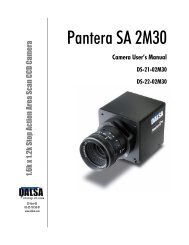
DS-24-0<strong>2M30</strong> and DS-25-0<strong>2M30</strong> <strong>User</strong>’s <strong>Manual</strong> 13<br />
Figure 7: MDR26 Connector<br />
13<br />
MDR26 Female<br />
1<br />
26<br />
14<br />
Mating Part: 3M 334-31 ser ies<br />
Cable: 3M 14X 26-SZ LB-X X X -0LC* *<br />
Table 5: MDR26 Connector Reference<br />
Item Value Item Value<br />
Pinout Base Configuration Pinout Base Configuration<br />
1 Logic Gnd via 0 ohm resistor 14 Logic Gnd via 0 ohm resistor<br />
2 X0- 15 X0+<br />
3 X1- 16 X1+<br />
4 X2- 17 X2+<br />
5 Xclk- 18 Xclk+<br />
6 X3- 19 X3+<br />
7 SERTC+ 20 SERTC-<br />
8 SERTFG- 21 SERTFG+<br />
9 CC1- 22 CC1+<br />
10 CC2+ 23 CC2-<br />
11 CC3- 24 CC3+<br />
12 CC4+ 25 CC4-<br />
13 Logic Gnd via 0 ohm resistor 26 Logic Gnd via a 0 ohm resistor<br />
Notes:<br />
*Exterior Overshield is connected to the shells of the connectors on both ends.<br />
**3M part 14X26-SZLB-XXX-0LC is a complete cable assembly, including connectors.<br />
Unused pairs should be terminated in 100 ohms at both ends of the cable.<br />
Table 6: DALSA Camera Control Configuration<br />
Signal Configuration<br />
CC1<br />
CC2<br />
CC3<br />
CC4<br />
EXSYNC<br />
Spare<br />
Spare<br />
Spare<br />
See Appendix B on page 51 for the complete DALSA Camera Link configuration table,<br />
and refer to the DALSA Web site, vfm.dalsa.com, for the official Camera Link documents.<br />
DALSA 03-32-10157-02