Create successful ePaper yourself
Turn your PDF publications into a flip-book with our unique Google optimized e-Paper software.
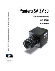
DS-24-0<strong>2M30</strong> and DS-25-0<strong>2M30</strong> <strong>User</strong>’s <strong>Manual</strong> 12<br />
2.2 Input/Output Connectors and LED<br />
The camera uses a:<br />
• Diagnostic LED for monitoring the camera. See LED Status Indicator section below<br />
for details.<br />
• High-density 26-pin MDR26 connector for Camera Link control signals, data signals,<br />
and serial communications. Refer to section 2.2.2 Camera Link Data Connector for<br />
details.<br />
• 6-pin Hirose connector for power. Refer to section 2.2.3 Power Connector for details.<br />
Figure 6: Pantera SA <strong>2M30</strong> Input and Output<br />
CameraLink<br />
Diagnostic LED<br />
+11V to +25V and Ground<br />
!<br />
WARNING: It is extremely important that you apply the appropriate voltages to your camera.<br />
Incorrect voltages will damage the camera. See section 2.2.3 Power Connector for details.<br />
2.2.1 LED Status Indicator<br />
Table 4: Diagnostic LED<br />
Color of Status LED<br />
Flashing Green<br />
Solid Green<br />
Flashing Red<br />
Solid Red<br />
Meaning<br />
Camera Initialization<br />
Camera Ready<br />
Fatal Error<br />
2.2.2 Camera Link Data Connector<br />
Warning, such as firmware did not load or Voltage out of limit.<br />
The Camera Link interface is implemented as a Base Configuration in the Pantera SA<br />
cameras. A Base Configuration uses 1 MDR26 connector and 1 Channel Link chip. The<br />
main characteristics of the Base Configuration are:<br />
• Ports supported: A, B, C<br />
• Serializer bit width: 28<br />
• Number of chips: 1<br />
• Number of MDR26 connectors: 1<br />
DALSA 03-32-10157-02