Spyder 3 Camera User's Manual GigE Dual Line - Frame Grabbers
Spyder 3 Camera User's Manual GigE Dual Line - Frame Grabbers
Spyder 3 Camera User's Manual GigE Dual Line - Frame Grabbers

Create successful ePaper yourself
Turn your PDF publications into a flip-book with our unique Google optimized e-Paper software.
<strong>Spyder</strong> 3 <strong>GigE</strong> User’s <strong>Manual</strong><br />
25<br />
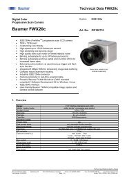
2.4.2 Power Connector<br />
Figure 9: Hirose 6-pin Circular Male—Power Connector<br />
Hirose 6-pin Circular Male Table 4: Hirose Pin Description<br />
1 6<br />
Pin Description Pin Description<br />
2 5<br />
1 Min +12 to Max +15V 4 GND<br />
3 4<br />
2 Min +12 to Max +15V 5 GND<br />
Mating Part: HIROSE<br />
HR10A-7P-6S<br />
3 Min +12 to Max +15V 6 GND<br />
!<br />
The camera requires a single voltage input (+12 to +15V). The camera meets all<br />
performance specifications using standard switching power supplies, although wellregulated<br />
linear supplies provide optimum performance.<br />
WARNING: When setting up the camera’s power supplies follow these guidelines:<br />
• Apply the appropriate voltages<br />
• Protect the camera with a fast-blow fuse between power supply and camera.<br />
• Do not use the shield on a multi-conductor cable for ground.<br />
• Keep leads as short as possible to reduce voltage drop.<br />
• Use high-quality linear supplies to minimize noise.<br />
Note: <strong>Camera</strong> performance specifications are not guaranteed if your power supply does not meet<br />
these requirements.<br />
DALSA offers a power supply with attached 6’ power cable that meets the <strong>Spyder</strong> 3 <strong>GigE</strong><br />
camera’s requirements, but it should not be considered the only choice. Many high<br />
quality supplies are available from other vendors. Visit the 12Hwww.dalsa.com Web site for a<br />
list of companies that make power supplies that meet the camera’s requirements. The<br />
companies listed should not be considered the only choices.<br />
2.4.3 GPIO Connector<br />
The GPIO connector is used to control external signals. For example, the GPIO connector<br />
can be used to control EXSYNC, PRIN (pixel reset), and direction signals.<br />
Figure 10: GPIO Connector and Pin Numbers<br />
1<br />
5<br />
15<br />
11<br />
Table 5: GPIO Connector Pinout<br />
Pin Signal Description<br />
1 INPUT_ 0+ LVDS/TTL format (positive)<br />
DALSA 03-032-10158-06