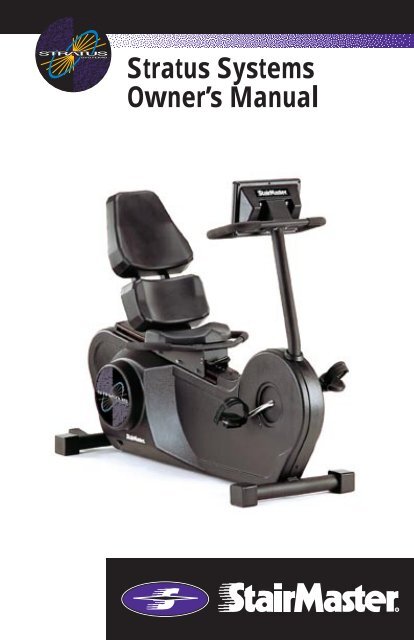
Stratus Systems Owner's Manual - GymStore.com
Stratus Systems Owner's Manual - GymStore.com
Stratus Systems Owner's Manual - GymStore.com

Create successful ePaper yourself
Turn your PDF publications into a flip-book with our unique Google optimized e-Paper software.
<strong>Stratus</strong> <strong>Systems</strong><br />
Owner’s <strong>Manual</strong>
Printed in the United States.<br />
© 1997, 2000 StairMaster Health & Fitness Products<br />
All rights reserved.<br />
Corporate Headquarters<br />
12421 Willows Road N.E., Suite 100<br />
Kirkland, WA 98034<br />
(800) 635-2936<br />
(425) 823-1825<br />
Fax (425) 823-9490<br />
www.stairmaster.<strong>com</strong><br />
P/N 21442-H<br />
©1997, 2000 StairMaster Health & Fitness Products and StairMaster are either a registered<br />
trademark or trademark of StairMaster Health & Fitness Products in the<br />
United States and/or other countries. StairMaster is a Rutledge Capital <strong>com</strong>pany.<br />
Page iii
WARRANTY<br />
This is to certify that the StairMaster ® <strong>Stratus</strong> systems cycle ergometer is<br />
warranted for a period of three years by StairMaster Health & Fitness Products<br />
to be free of all defects in materials and workmanship. This warranty does not<br />
apply to any defect caused by negligence, misuse, accident, alteration, improper<br />
maintenance, or an “act of God.” This warranty is nontransferable from the<br />
original owner.<br />
If, within three years from the date of purchase, any part of the StairMaster<br />
<strong>Stratus</strong> systems cycle ergometer should fail to operate properly (except any<br />
accessories or the battery), contact our Customer Service<br />
Department to report the problem. International customers should contact their<br />
local distributor. When calling, please be prepared to provide our customer<br />
service representative with the following information:<br />
Page iv<br />
• Your name, shipping address, and telephone number;<br />
• The model number of the inoperable unit;<br />
• The serial number of the inoperable unit (located on the frame);<br />
• The date(s) of purchase for the inoperable unit(s);<br />
• Your billing address.<br />
This information will ensure that you are the only one ordering parts under<br />
your warranty protection. If warranty replacement parts are shipped to you, you<br />
may be required to return the inoperable part. To facilitate this process, the<br />
following policy has been established:<br />
• Please call our Customer Service Department to receive a return goods<br />
authorization prior to shipment.<br />
• StairMaster Health & Fitness Products will incur all freight (i.e.,<br />
shipping and handling) charges for warranty parts ordered for a product<br />
that is less than 45 days old. The parts will be shipped to you via an<br />
overnight courier.<br />
• The customer is responsible for freight charges on warranty parts for<br />
products that are more than 45 days old. Customers will not be<br />
responsible for the return shipment of the inoperable parts (see below).<br />
• Some inoperable warranty parts must be promptly returned to our<br />
Customer Service Department. We will pay the shipping cost for the<br />
inoperable warranty parts. Detailed instructions are included with each<br />
warranty replacement part shipment.<br />
StairMaster Health & Fitness Products neither makes, assumes, nor<br />
authorizes any representative or other person to make or assume for us, any<br />
other warranties whatsoever, whether expressed or implied, in connection with<br />
the sale, service, or shipment of our products. We reserve the right to make<br />
changes and improvements in our products without incurring any obligation to<br />
similarly alter products previously purchased. In order to maintain your product<br />
warranty and to ensure the safe and efficient operation of your StairMaster<br />
<strong>Stratus</strong> systems cycle ergometer, only authorized replacement parts can be used.<br />
This warranty is void if any parts other than those provided by StairMaster<br />
Health & Fitness Products are used.<br />
* Note: Aerosol products cannot be transported via air.
PREFACE<br />
The StairMaster ® <strong>Stratus</strong> systems cycle ergometer is a safe and effective way<br />
to develop aerobic fitness while conditioning the major muscles of the lower<br />
body. In order to get the best results, and to keep your machine in peak operating<br />
condition, you should carefully read and follow the guidelines presented in this<br />
manual.<br />
WHAT IS IN THIS MANUAL?<br />
This manual includes sections on safety, installation, operating instructions,<br />
preventive maintenance, and detailed information on troubleshooting and repair<br />
procedures. An appendix at the end of the manual provides important phone<br />
numbers and drawings.<br />
WHAT IS THE STAIRMASTER STRATUS CYCLE<br />
ERGOMETER?<br />
The <strong>Stratus</strong> systems cycle ergometers have 14 levels of intensity for the<br />
MANUAL program and 20 levels of intensity for the other programs. The <strong>Stratus</strong><br />
uses a variable resistance system to maintain constant power within any given<br />
intensity level. The resistance decreases as you pedal faster and increases as<br />
you pedal slower. The variable resistance system ensures you will do the same<br />
amount of work regardless of how fast or slow you pedal.<br />
WHAT IS THE BATTERY CHARGER USED FOR?<br />
Plug in the battery charger only to recharge a weak battery. Exercising on the<br />
<strong>Stratus</strong> cycle while the battery charger is connected will not damage the<br />
machine, but will affect the power output (watts) statistics.<br />
Page v
CONTENTS<br />
SAFETY GUIDELINES ....................................................................................... 1<br />
INTRODUCTION ................................................................................................ 3<br />
INSTALLATION INSTRUCTIONS..................................................................... 5<br />
BASIC OPERATING INSTRUCTIONS ............................................................. 6<br />
Adjustments .......................................................................................... 6<br />
The ATTRACT Mode .............................................................................. 7<br />
Basic Instructions For First-Time Users ................................................ 7<br />
GENERAL EXERCISE GUIDELINES ................................................................. 9<br />
Setting a Goal ....................................................................................... 9<br />
Flexibility Training ................................................................................. 9<br />
Exercise Principles ................................................................................ 10<br />
CONTACT HEART RATE (OPTIONAL) ............................................................. 11<br />
POLAR ® HEART RATE ....................................................................................... 12<br />
CONSOLE ........................................................................................................... 13<br />
Text Bar ................................................................................................. 13<br />
Display .................................................................................................. 13<br />
Function Keypad .................................................................................... 14<br />
Exercise Program Keypad ..................................................................... 16<br />
Road Race ............................................................................................. 25<br />
Custom Exercise Programs ................................................................... 26<br />
Custom Scrolling Message ................................................................... 27<br />
Editing the Scrolling Message .............................................................. 28<br />
Set Maximum Workout Length ............................................................. 29<br />
Changing to the Clinical Mode ............................................................. 29<br />
Changing the Console Units and Prompt Language ............................. 29<br />
Console Codes ...................................................................................... 30<br />
MAINTENANCE INSTRUCTIONS ................................................................... 31<br />
Helpful Hints ......................................................................................... 31<br />
Tool List ................................................................................................. 31<br />
Maintenance Records ........................................................................... 31<br />
Page vi
CONTENTS<br />
Initial Service ........................................................................................ 32<br />
Preventive Maintenance ....................................................................... 32<br />
TROUBLESHOOTING GUIDELINES ................................................................ 36<br />
General Troubleshooting Guidelines..................................................... 36<br />
Systematic Electrical Troubleshooting.................................................. 36<br />
Systematic Mechanical Troubleshooting.............................................. 38<br />
Console Diagnostic Tests ...................................................................... 40<br />
PARTS REMOVAL AND REPLACEMENT ....................................................... 44<br />
Covers ................................................................................................... 44<br />
Console ................................................................................................. 44<br />
Handlebar Assembly ............................................................................. 46<br />
Seat ....................................................................................................... 47<br />
Seat Location Post (3300 CE only) ........................................................ 48<br />
Seat Track (3900 RC only) ..................................................................... 49<br />
Drive Chain ............................................................................................ 49<br />
Intermediate Shaft Assembly ............................................................... 50<br />
Pedals .................................................................................................... 51<br />
Crank and Bottom Bracket Assembly ................................................... 51<br />
GROUNDING INSTRUCTIONS ........................................................................ 54<br />
NOTICE OF FCC COMPLIANCE ....................................................................... 55<br />
APPENDICES<br />
Important Phone Numbers .................................................................... 56<br />
Battery Recycling Centers ..................................................................... 57<br />
Figures 11 - 24 ...................................................................................... 58<br />
Wiring Diagram ..................................................................................... 73<br />
LIST OF TABLES<br />
Table 1: Specifications .......................................................................... 4<br />
Table 2: Fitness Rating Norms .............................................................. 18<br />
Table 3: Character Codes ...................................................................... 28<br />
Table 4: Console Codes ......................................................................... 30<br />
Table 5: Preventive Maintenance Schedule ......................................... 35<br />
Page vii
CONTENTS<br />
LIST OF ILLUSTRATIONS<br />
Figure 1: Major Parts, 3300 CE ............................................................. 3<br />
Figure 2: Major Parts, 3900 RC ............................................................. 4<br />
Figure 3: End Caps ................................................................................ 5<br />
Figure 4: <strong>Stratus</strong> <strong>Systems</strong> Console ....................................................... 13<br />
Figure 5: Fat Burner ............................................................................... 19<br />
Figure 6: Fat Burner Plus ....................................................................... 20<br />
Figure 7: Rolling Hills ............................................................................ 21<br />
Figure 8: Aerobic Training ..................................................................... 22<br />
Figure 9: Cross Country ......................................................................... 23<br />
Figure 10: Speed Training ..................................................................... 24<br />
Figure 11: Cover Fasteners ................................................................... 59<br />
Figure 12: Cover Fastener Location, 3300 CE ....................................... 60<br />
Figure 13: Cover Fastener Location, 3900 RC ....................................... 61<br />
Figure 14: Right Side View, 3300 CE ..................................................... 62<br />
Figure 15: Left Side View, 3300 CE ....................................................... 63<br />
Figure 16: Right Side View, 3900 RC .................................................... 64<br />
Figure 17: Left Side View, 3900 RC ....................................................... 65<br />
Figure 18: Seat Adjustment Pin Assembly, 3300 CE............................. 66<br />
Figure 19: Seat Assembly, 3900 RC ...................................................... 67<br />
Figure 20: Drive Chain Tension ............................................................. 68<br />
Figure 21: Intermediate Shaft Assembly .............................................. 69<br />
Figure 22: J Bolt Assembly ................................................................... 70<br />
Figure 23: Crank Assembly ................................................................... 71<br />
Figure 24: Alternator/Flywheel Assembly ............................................ 72<br />
Wiring Diagram 1: Wiring Schematic ................................................... 73<br />
Page viii
SAFETY GUIDELINES<br />
WHEN USING ELECTRICAL EQUIPMENT, ALWAYS FOLLOW THESE BASIC PRECAUTIONS:<br />
IMPORTANT SAFETY INSTRUCTIONS<br />
!<br />
This symbol appearing throughout this manual<br />
means Attention! Be Alert! Your safety is involved.<br />
The following definitions apply to the words “Danger” and “Warning”<br />
found throughout this manual:<br />
DANGER - Used to call attention to IMMEDIATE hazards which, if not<br />
avoided, will result in immediate, serious personal injury or loss of life.<br />
WARNING - Used to call attention to POTENTIAL hazards that could<br />
result in personal injury or loss of life.<br />
READ ALL INSTRUCTIONS BEFORE USING THE MACHINE.<br />
!<br />
!<br />
DANGER<br />
WARNING<br />
To reduce the risk of electrical shock, always unplug<br />
the external power supply from the AC wall outlet<br />
before cleaning, maintaining, or repairing.<br />
To reduce the risk of burns, electric shock, or injury<br />
to persons:<br />
1. The external power supply should always be unplugged from the AC wall<br />
outlet before removing or installing parts. Never make adjustments or<br />
repairs while an exercise program is in progress.<br />
2. Close supervision is necessary whenever the machine is used by or near<br />
children, invalids, or disabled persons.<br />
3. Keep your hands away from all moving parts and keep your feet on the<br />
pedals while exercising. Do not operate the machine with the side covers<br />
removed.<br />
Page 1
SAFETY GUIDELINES<br />
4. Use this machine only for its intended use as described in this <strong>Manual</strong>. Do<br />
not use parts, attachments, or accessories other than those provided by<br />
StairMaster Health & Fitness Products.<br />
5. Do not use the external power supply if it has a damaged cord or plug, if it<br />
is not working properly, if it has been dropped or damaged, or dropped<br />
into water. Contact our Customer Service Department to arrange for the<br />
return of damaged parts.<br />
6. Connect the external power supply to a properly grounded AC wall outlet;<br />
refer to the “Grounding Instructions” section. Keep all cords away from<br />
heated surfaces.<br />
7. To disconnect the external power supply, remove the plug from the AC<br />
wall outlet.<br />
8. Never drop or insert any object into any opening on the machine.<br />
9. Do not operate where aerosol (spray) products are being used.<br />
10. Always wear insulated gloves when handling batteries.<br />
11. Do not crush, incinerate, or dismantle the battery. The electrolyte<br />
contains sulfuric acid which can cause serious damage to eyes<br />
and skin. Should this occur, flush profusely with water and seek<br />
medical attention.<br />
12. Do not use the machine outdoors.<br />
The safety level given by the design of this equipment can only be maintained<br />
when the equipment is regularly examined for damage and wear. Inoperable<br />
<strong>com</strong>ponents shall be replaced immediately or the equipment shall be put out of<br />
use until it is repaired. Failure to follow all guidelines may <strong>com</strong>promise the<br />
effectiveness of the exercise experience, expose yourself (and possibly others) to<br />
injury, and reduce the longevity of the machine. Follow all training instructions<br />
listed in the manual and/or on the machine. Physical injury may result from<br />
incorrect or excessive training.<br />
Page 2<br />
SAVE THESE INSTRUCTIONS
INTRODUCTION<br />
Before leaving the StairMaster manufacturing facility in Tulsa, Oklahoma, your<br />
StairMaster ® <strong>Stratus</strong> cycle ergometer was thoroughly inspected and tested to<br />
ensure proper operation. The major parts of the StairMaster <strong>Stratus</strong> 3300 CE and<br />
3900 RC are shown in Figures 1 and 2.<br />
Figure 1: Major Parts, 3300 CE<br />
Page 3
INTRODUCTION<br />
Figure 2: Major Parts, 3900 RC<br />
Throughout this manual, all references to the left or right side and to the front or<br />
back are made as if you were on the machine, ready to exercise. For example, the<br />
drive chain is located on the right side of the machine. The dimensions of the<br />
machine are listed in Table 1.<br />
Table 1. Dimensions of the <strong>Stratus</strong> <strong>Systems</strong> Cycle Ergometer<br />
3300 CE 3900 RC<br />
Length 50 inches (127 cm) 64 inches (163 cm)<br />
Width 22 inches (56 cm) 21 inches (53 cm)<br />
Height 57 inches (145 cm) 42 inches (107 cm)<br />
Weight 125 pounds (57 kg) 157 pounds (71 kg)<br />
Page 4
INSTALLATION INSTRUCTIONS<br />
Assemble your machine before use. Machines shipped outside the United States<br />
need to be uncrated before they can be assembled; refer to the “Uncrating<br />
Instructions” included with your machine for the details.<br />
1. Remove all shipping material and the battery charger from the<br />
console.<br />
2. Make sure the machine is level before you use it for the first time. The<br />
four rubber end caps (see Figure 3) are designed to <strong>com</strong>pensate for<br />
slightly uneven floors. Each face of the caps is a different thickness.<br />
Twist the caps to stabilize the machine.<br />
Figure 3: End Caps<br />
3. Pedal the cycle to turn on the console. The console should produce an<br />
audible sound and display a simulated EKG signal in the display area.<br />
If it does not, contact our Customer Service Department. Refer to the<br />
Appendix for the appropriate phone number.<br />
Page 5
BASIC OPERATING INSTRUCTIONS<br />
ADJUSTMENTS<br />
You should check two adjustments before using your StairMaster ® <strong>Stratus</strong><br />
systems cycle ergometer: the seat height and the pedal footstrap length.<br />
Seat Height Adjustment on the <strong>Stratus</strong> 3300 CE Cycle Ergometer<br />
Sit on the seat. Put both feet onto the pedals and into the footstraps. Pedal<br />
slowly and then stop when one leg is extended and your foot is as close to the<br />
floor as possible. The knee of the extended leg should be slightly bent when the<br />
sole of your foot is parallel to the floor. If you need to adjust the seat height, get<br />
off the bike and stand to one side. The seat adjustment knob is located on the<br />
frame tube just below the front part of the seat. Hold onto the seat with one<br />
hand and pull out on the seat adjustment knob with your other hand. You may<br />
need to lift up on the seat to disengage the seat pin. Lower or raise the seat as<br />
necessary.<br />
! WARNING<br />
TO ELIMINATE THE RISK OF INJURY, DO NOT ADJUST THE SEAT HEIGHT<br />
WHILE ON THE STRATUS 3300 CE CYCLE ERGOMETER. MAKE SURE THAT<br />
THE SEAT ADJUSTMENT PIN COMPLETELY ENGAGES THE HOLE IN THE SEAT<br />
POST BEFORE REMOUNTING THE BIKE.<br />
Seat Adjustment on the <strong>Stratus</strong> 3900 RC Cycle Ergometer<br />
Sit on the seat. Put both feet onto the pedals and into the footstraps. Pedal<br />
slowly and then stop when one leg is extended. The knee of the extended leg<br />
should be slightly bent. The seat adjustment lever is in front of the seat base.<br />
Remain seated and keep your feet on the pedals. Pull up on the lever and slide<br />
forward or backward as necessary. Release the lever and make sure the seat is<br />
locked in place by trying to move the seat forward and backward.<br />
Page 6
Footstrap Adjustment<br />
BASIC OPERATING INSTRUCTIONS<br />
To ensure your feet are properly secured to the pedals, you need to check the<br />
position of the footstraps. Position your foot so that the ball of your foot is over<br />
the pedal spindle. The pedal footstraps should be tight enough to secure your<br />
feet to the pedals but not so tight so as to cut off the circulation. If you need to<br />
adjust the footstrap length, get off the bike and stand to one side. There are two<br />
adjusting holes on the inside footstrap mount and four holes on the outside<br />
footstrap mount. Most shoes can be ac<strong>com</strong>modated by adjusting the outside<br />
mounting holes. To make the necessary adjustments, grasp the pedal with one<br />
hand and the outside end of the footstrap with your other hand. Carefully pull the<br />
outside end of the footstrap off the tab on the pedal. Insert the proper hole of the<br />
footstrap onto the pedal tab. If you need to make additional adjustments, repeat<br />
the process with the inside mounting holes of the footstrap.<br />
THE ATTRACT MODE<br />
All workouts on the StairMaster ® <strong>Stratus</strong> cycle ergometer start from the AT-<br />
TRACT mode. The console displays an EKG signal or scrolls a message in the text<br />
bar when it is in the ATTRACT mode. You must pedal to get the console into the<br />
ATTRACT mode.<br />
You can customize the ATTRACT mode by programming your own<br />
scrolling message. Refer to the “Customizing the Text Bar Scrolling Message”<br />
section for instructions.<br />
BASIC INSTRUCTIONS FOR FIRST-TIME USERS<br />
1. Warm up with light calisthenics and easy stretching exercises for at<br />
least five minutes before beginning your exercise program.<br />
! WARNING<br />
IF AT ANY TIME DURING YOUR WORKOUT YOU FEEL CHEST PAIN,<br />
EXPERIENCE SEVERE MUSCULAR DISCOMFORT, FEEL FAINT, OR ARE SHORT OF<br />
BREATH, STOP EXERCISING IMMEDIATELY. IF THE CONDITION PERSISTS, YOU<br />
SHOULD CONSULT YOUR MEDICAL DOCTOR IMMEDIATELY.<br />
Page 7
BASIC OPERATING INSTRUCTIONS<br />
2. Position yourself <strong>com</strong>fortably on the bike and begin pedaling.<br />
3. Select the MANUAL exercise program so you can control the pace of<br />
your first workout and get used to the exercise motion.<br />
Console Set-Up<br />
1. Press [MANUAL] and then press [ENTER].<br />
2. The console will prompt you to enter your body weight. Enter your<br />
weight in pounds (or kilograms if the console is set up for<br />
metric units). Correct entry errors by pressing [CLEAR] before you<br />
press [ENTER].<br />
3. The console will prompt you to enter the workout time in one minute<br />
increments between five and 60 minutes. Press [1], [0], [ENTER] to<br />
exercise for ten minutes.<br />
Begin Exercising<br />
1. Pedal at a <strong>com</strong>fortable pace. Although the resistance decreases as<br />
you pedal faster, the intensity (watts) stays the same.<br />
2. Press [+ ARROW] and [- ARROW] to adjust your intensity level.<br />
3. Select an intensity level that allows you to stay at a <strong>com</strong>fortable pace.<br />
Harder is not always better. Exercise at a level that is consistent with<br />
your fitness level.<br />
4. The intensity (watts) remains constant provided you pedal at least 50<br />
RPM. A message will prompt you to "Pedal Faster" if you pedal slower<br />
than 50 RPM.<br />
5. Cool down after you get off the machine by walking or stretching for<br />
at least five minutes.<br />
Page 8
SETTING A GOAL<br />
GENERAL EXERCISE GUIDELINES<br />
The first step to a successful exercise program is to set realistic goals and<br />
objectives. Are you wanting an exercise program that is geared to build muscle,<br />
maintain muscle tone, or lose weight? In order to ensure that you fully receive all<br />
the benefits of a sound exercise program, you need to first identify the existence<br />
(if any) of risk factors that may influence the design of your exercise program.<br />
Based upon a <strong>com</strong>prehensive analysis of your personal exercise needs and<br />
interests, you should then develop (or have developed for you by a <strong>com</strong>petent or<br />
trained professional) an individualized program of exercise that is enjoyable,<br />
easy, and yet challenging. Your greatest health benefit will <strong>com</strong>e from a lifestyle<br />
change that encourages a lifetime of physical activity.<br />
One way to guarantee success in reaching your goal is to eat correctly. A<br />
well-rounded diet provides the proteins, carbohydrates, fats, vitamins, minerals,<br />
and water necessary for good health. If you are unsure of your dietary needs,<br />
seek the advise of your physician, an exercise professional, or visit your local<br />
bookstore for more information on nutrition.<br />
FLEXIBILITY TRAINING*<br />
Achieving and maintaining an adequate range of motion should always be<br />
objectives of a <strong>com</strong>prehensive exercise program. The warm-up phase of your<br />
exercise session should include some type of light warm-up activity to increase<br />
both your heart rate and your body temperature, which is then followed by<br />
flexibility exercises that are specifically designed to stretch the musculature<br />
around your body’s major skeletal joints. Attempting to stretch a cold muscle can<br />
be dangerous to the soft tissues surrounding the muscle. No matter how<br />
controlled the movement, forcing a muscle through a full range of motion (and<br />
beyond) without appropriately warming up is both unsafe and counterproductive.<br />
A general exercise program for achieving and maintaining flexibility should<br />
adhere to the following guidelines:<br />
•Frequency<br />
•Intensity<br />
•Duration<br />
- daily<br />
- to a position of mild dis<strong>com</strong>fort<br />
- 10-30 seconds for each stretch<br />
Page 9
GENERAL EXERCISE GUIDELINES<br />
•Repetitions<br />
•Type<br />
- 2-6 for each stretch<br />
- static, with a major emphasis on the low back and<br />
hamstrings area because of the high prevalence<br />
of low-back pain syndrome in our society.<br />
EXERCISE PRINCIPLES*<br />
The American College of Sports Medicine has developed a position paper<br />
concerning exercise programs for healthy adults and the need for guidelines. The<br />
following re<strong>com</strong>mendations concern the quantity and quality of (exercise)<br />
training for developing and maintaining cardiorespiratory fitness in a healthy<br />
adult:<br />
•Frequency<br />
•Intensity<br />
•Duration<br />
•Mode of Activity<br />
•Rate of Progression<br />
-3 to 5 days per week<br />
-50% - 85% of maximum oxygen<br />
uptake (VO 2 max<br />
)<br />
-20 to 60 minutes of continuous<br />
aerobic activity<br />
-Any activity that uses the large<br />
muscle groups, that can be<br />
maintained continuously, and is<br />
rhythmical and aerobic in nature.<br />
-Initial Conditioning - 4 to 6 weeks; lowend<br />
intensity (40% - 60% VO 2 max<br />
); low-end<br />
duration (15 to 20 minutes).<br />
-Improvement Stage - 6 weeks to 6 months;<br />
moderate intensity; moderate duration.<br />
-Maintenance Stage - 6 months plus;<br />
moderate to high intensity; moderate to<br />
high duration.<br />
*Note: Some of the material contained in this section is adapted from The<br />
StairMaster ® Fitness Handbook 2nd Ed., James A Peterson, and Cedric X. Bryant<br />
(editors), Sagamore Publishing, 1995.<br />
Page 10
CONTACT HEART RATE<br />
The StairMaster ® <strong>Stratus</strong> <strong>Systems</strong> cycle ergometer features an optional digitized<br />
contact heart rate monitoring system. Through the use of stainless steel sensors<br />
built into the upper handles and sophisticated software, heart rate can be<br />
checked at any time during a workout.<br />
The heart generates a rhythmic, electronic signal each time it beats (the<br />
electrocardiogram or EKG signal). The sensors detect this electrical signal<br />
through the hands when the sensors are gripped during a workout. The signal is<br />
converted into a heart rate, which is displayed on the console.<br />
The contact heart rate system is very accurate (within 3% of the<br />
medical standard), but its ability to detect a heart rate signal is influenced by<br />
several factors. Movement of the muscles of the upper body produces an<br />
electrical signal that will interfere with the detection of the heart rate signal by<br />
the sensors. Movement of the hands while they are in contact with the sensors<br />
also produces interference. Calluses and hand lotion act as an insulating layer to<br />
reduce the signal strength. Also, the EKG signal generated by some individuals is<br />
not strong enough to be detected by the sensors. Typically, these individuals<br />
account for 5 - 7% of the population. Most people (between 93 – 95%) will not<br />
have a problem with the system provided interference from movement is<br />
minimal.<br />
Lightly grip the sensors with each hand. The heart rate display is<br />
shown automatically in the upper window the first time the sensors are touched.<br />
A valid signal is shown by a pulsating heart icon and the number of beats per<br />
minute next to the word “Pulse”. The heart icon will stop beating and two dashes<br />
replace the numbers when the sensors are released or an invalid signal is<br />
received.<br />
Page 11
POLAR ® HEART RATE<br />
The StairMaster ® <strong>Stratus</strong> cycle ergometer features Polar ® heart rate<br />
monitoring. The system consists of the receiver, located on the stepper, and<br />
a transmitter belt (purchased separately), worn across your chest. The transmitter<br />
belt senses the heart beat and sends a signal to the receiver. Your heart rate,<br />
in beats per minute, is shown on the console text bar.<br />
The transmitter belt attaches an identification number to your heart rate<br />
signal. Once the receiver locks on to your signal, it will ignore all other signals<br />
without your identification number. Now, two people can exercise<br />
side-by-side without interfering with each other's heart rate signal.<br />
Before you put the transmitter belt on, wet the two contact patches (the<br />
grooved rectangles on the reverse side of the belt). Secure the transmitter belt as<br />
high under the pectoral muscles (chest) as is <strong>com</strong>fortable. The transmitter belt<br />
should fit snugly and <strong>com</strong>fortably and allow normal breathing.<br />
When the console detects a heart rate signal, heart rate is shown in the<br />
display automatically. The word "PULSE", your heart rate in beats per minute, and<br />
a pulsing heart icon are displayed in the text bar.<br />
If you display a statistic other than heart rate during your workout, you<br />
can return to heart rate by pressing the white [0] key. Heart rate is part of the<br />
workout stats scrolling display. Average heart rate is shown at the end of your<br />
workout. If you wear a transmitter strap during the Fit Test, the average heart<br />
rate at the end of each stage is automatically used when estimating maximum<br />
aerobic capacity.<br />
Page 12
STRATUS SYSTEMS CONSOLE<br />
The StairMaster ® <strong>Stratus</strong> systems console is divided into four sections: the text<br />
bar, the display, the function keypad and the exercise program keypad (see<br />
Figure 4).<br />
TEXT BAR<br />
Figure 4: <strong>Stratus</strong> <strong>Systems</strong> Console<br />
Information regarding workout statistics and data entry is displayed or scrolled<br />
across the text bar. A countdown timer is located directly above the words<br />
"Interval Time". The timer shows the number of seconds remaining in the current<br />
interval.<br />
DISPLAY<br />
A profile of all exercise programs (except MANUAL and FIT TEST) appears in the<br />
display when you press its key. The taller the column, the higher the intensity<br />
(watts) for that interval. The flashing column shows your current interval. The<br />
flashing column moves from left to right across the display as you <strong>com</strong>plete each<br />
interval.<br />
Page 13
STRATUS SYSTEMS CONSOLE<br />
Function keypad<br />
The function keypad is located on the right side of the console. Nine of the keys<br />
on the keypad have two pieces of information on them—a number and a<br />
workout statistic. Before the exercise program begins, the numbers are used to<br />
enter data in response to the console prompts. During or immediately after the<br />
exercise program, the function keypad keys are used to recall workout statistics<br />
which are then displayed on the text bar.<br />
Page 14<br />
Time. Displays the elapsed time of your workout, in minutes and<br />
seconds.<br />
Speed. Displays the equivalent speed, in miles per hour (or<br />
kilometers per hour if your console is set to metric units), you<br />
would be traveling on a bicycle outdoors while riding at the same<br />
relative intensity.<br />
Distance. Provides a cumulative total of the equivalent distance,<br />
in miles (or kilometers if your console is set to metric units), you<br />
would have traveled while riding a bicycle outdoors at the same<br />
relative intensity.<br />
Watts. Displays the intensity in watts (746 watts = 1 horsepower). For<br />
all programs, except the constant resistance ROAD RACE, the watts<br />
remain constant in any given level as long as you pedal at least 50<br />
RPM. During a workout, this key displays the power output at that<br />
moment. Average power is shown during the workout summary.<br />
Intensity Level. Shows the current level between 1 (the easiest) and<br />
20 (the hardest). Shows the number of lights in the MANUAL program<br />
between 1 and 14.<br />
METs. Gives you the relative energy cost of exercise. MET stands for<br />
multiples of the resting metabolic rate. While you are sitting quietly,<br />
your body consumes oxygen at the rate of about 3.5 milliliters per<br />
kilogram of body mass per minute. When you exercise, your body<br />
needs more oxygen in order to function. For example, exercising at 10<br />
METs requires ten times the resting rate of oxygen consumption, or
STRATUS SYSTEMS CONSOLE<br />
about 35 milliliters per kilogram per minute. During a workout, this key<br />
shows the current MET level. During the workout summary, the<br />
average MET level is displayed.<br />
Calories. Provides a running total of the number of Calories burned<br />
during a workout.<br />
Enter. Confirms workout selections and stores the information used<br />
by the console to calculate workout statistics.<br />
Clear. Erases information from the console memory if pressed<br />
before [ENTER].<br />
[+] and [-] ARROWS. Increases or decreases the intensity level.<br />
Workout Stats. If pressed during your workout, all workout statistics<br />
continuously scroll across the text bar. Press any key to stop scrolling<br />
at that statistic.<br />
If [WORKOUT STATS] is pressed immediately after your<br />
workout, the workout summary statistics will scroll once across the<br />
text bar. Press any key to stop scrolling at that statistic.<br />
If [WORKOUT STATS] is pressed while the console is in the<br />
ATTRACT mode, the final totals from the last workout will scroll across<br />
the text bar. This summary is stored in the console memory until the<br />
next workout is started.<br />
Yes and No. Respond to console prompts.<br />
Start/Stop. If pressed while the console is in the ATTRACT mode, the<br />
console will display the "Select A Program" prompt. If it is pressed at<br />
any other time, the console will pause for 10 seconds.<br />
Page 15
STRATUS SYSTEMS CONSOLE<br />
EXERCISE PROGRAM KEYPAD<br />
The purple exercise keypad is located below the display and to the left of the<br />
function keypad. While the console is in the ATTRACT mode, press one of the<br />
exercise program keys to preview the desired workout.<br />
The sequence of prompts for the preset exercise programs is slightly<br />
different than the sequence described earlier for the MANUAL program. After<br />
you press one of the exercise program keys, the exercise program profile is<br />
scrolled across the display.<br />
After the profile is scrolled, the prompts are:<br />
• “PRESS ENTER KEY TO SELECT”<br />
• “ENTER BODY WEIGHT” -- type in your body weight in<br />
pounds (or kilograms if your console is set to metric units).<br />
• “ENTER LEVEL 1 - 20” -- select your intensity level with<br />
level 1 being the easiest and level 20 the hardest.<br />
• “ENTER TIME 5 - 60” -- select the workout duration in one<br />
minute increments from five to 60.<br />
The Quick Start Option<br />
You can begin a manually-paced workout without pressing any keys just by<br />
pedaling for 15 seconds. This program will last for 15 minutes.<br />
You can quickly start a preset workout by first pressing one of the<br />
purple exercise program keys and then pressing [ENTER] twice. You do not have<br />
to enter any other information. The length of the workout is set automatically<br />
and varies with the program. Quick starting MANUAL gives you a 15 minute<br />
workout. The preset workouts last five minutes for every thirty intervals. So, a 60<br />
interval program will last 10 minutes. The workout stats available are time,<br />
speed, distance, watts, level, calories, RPM, and pulse (if wearing a transmitter).<br />
The Fit Test does not have a quick start option.<br />
Page 16
Fit Test<br />
STRATUS SYSTEMS CONSOLE<br />
The Fit Test is a program developed by the YMCA to estimate your maximum<br />
aerobic capacity based on your heart rate response to submaximal exercise. Start<br />
the Fit Test by pressing [FIT TEST], [ENTER]. You will be prompted to enter your<br />
weight, age, and gender after a short message is scrolled across the text bar.<br />
The Fit Test is a series of three minute stages of increasing intensity.<br />
Maintain a steady pedal rate of 50 - 70 RPM throughout the entire test. The first<br />
stage is a warm-up at 50 watts. At the end of the three minute (180 seconds)<br />
warm-up, you will need to enter your heart rate. If you are wearing a heart rate<br />
transmitter, your heart rate is entered automatically.<br />
NOTE: Keep pedaling until the end of the Fit Test. The results will be<br />
invalid if you do not maintain a steady pedal rate for the entire test.<br />
The console will prompt you to find your pulse; use the artery below<br />
your thumb in your wrist or the artery in the side of your neck. Start counting the<br />
beats when the console prompts you--the first beat you feel is zero and then one<br />
and so on. Enter the number of beats you counted in ten seconds.<br />
The intensity of the remaining stages is based on your heart rate<br />
response to the warm-up. The intensity of each successive stage will increase<br />
until you have entered two consecutive heart rates between 19 and 25 counts<br />
(115 - 150 beats per minute). The test typically lasts from nine to 15 minutes.<br />
At the end of the Fit Test, your results scroll across the text bar. Prior to<br />
a three minute cool-down, your estimated maximum aerobic capacity is shown in<br />
METs. Next, your results are <strong>com</strong>pared to normative values for others of your age<br />
and gender (see Table 2). Your results are stored in the console until the next<br />
person starts an exercise program. Press [WORKOUT STATS] to review your<br />
results.<br />
Page 17
○ ○ ○ ○ ○ ○ ○ ○ ○ ○ ○ ○ ○ ○ ○ ○ ○ ○ ○ ○ ○ ○ ○ ○<br />
○ ○ ○ ○ ○ ○ ○ ○ ○ ○ ○ ○ ○ ○ ○ ○ ○ ○ ○ ○ ○ ○ ○ ○<br />
○ ○ ○ ○ ○ ○ ○ ○ ○ ○ ○ ○ ○ ○ ○ ○ ○ ○ ○ ○ ○ ○ ○ ○<br />
○ ○ ○ ○ ○ ○ ○ ○ ○ ○ ○ ○ ○ ○ ○ ○ ○ ○ ○ ○ ○ ○ ○ ○ ○ ○ ○ ○ ○ ○ ○ ○ ○ ○ ○ ○ ○ ○ ○ ○ ○<br />
○ ○ ○ ○ ○ ○ ○ ○ ○ ○ ○ ○ ○ ○ ○ ○ ○ ○ ○ ○ ○ ○ ○ ○ ○ ○ ○ ○ ○ ○ ○ ○ ○ ○ ○ ○ ○ ○ ○ ○ ○<br />
○ ○ ○ ○ ○ ○ ○ ○ ○ ○ ○ ○ ○ ○ ○ ○ ○ ○ ○ ○ ○ ○ ○ ○ ○ ○ ○ ○ ○ ○ ○ ○ ○ ○ ○ ○ ○ ○ ○ ○ ○<br />
○ ○ ○ ○ ○ ○ ○ ○ ○ ○ ○ ○ ○ ○ ○ ○ ○ ○ ○ ○ ○ ○ ○ ○ ○ ○ ○ ○ ○ ○ ○ ○ ○ ○ ○ ○ ○ ○ ○ ○ ○<br />
○ ○ ○ ○ ○ ○ ○ ○ ○ ○ ○ ○ ○ ○ ○ ○ ○ ○ ○ ○ ○ ○ ○ ○ ○ ○ ○ ○ ○ ○ ○ ○ ○ ○ ○ ○ ○ ○ ○ ○ ○<br />
○ ○ ○ ○ ○ ○ ○ ○ ○ ○ ○ ○ ○ ○ ○ ○ ○ ○ ○ ○ ○ ○ ○ ○ ○ ○ ○ ○ ○ ○ ○ ○ ○ ○ ○ ○ ○ ○ ○ ○ ○<br />
○ ○ ○ ○ ○ ○ ○ ○ ○ ○ ○ ○ ○ ○ ○ ○ ○ ○ ○ ○ ○ ○ ○ ○ ○ ○ ○ ○ ○ ○ ○ ○ ○ ○ ○ ○ ○ ○ ○ ○ ○<br />
○ ○ ○ ○ ○ ○ ○ ○ ○ ○ ○ ○ ○ ○ ○ ○ ○ ○ ○ ○ ○ ○ ○ ○<br />
○ ○ ○ ○ ○ ○ ○ ○ ○ ○ ○ ○ ○ ○ ○ ○ ○ ○ ○ ○ ○ ○ ○ ○<br />
STRATUS SYSTEMS CONSOLE<br />
Table 2. Fitness Rating Norms for <strong>Stratus</strong> <strong>Systems</strong><br />
Cycle Ergometer Aerobic Fitness Test (METs)<br />
Rating Low Fair Average Above Average Superior<br />
Gender/Age<br />
Men<br />
20-29
STRATUS SYSTEMS CONSOLE<br />
The Fat Burner program (Figure 5) is a 60 interval workout designed for<br />
people just starting a weight control program. The Fat Burner Plus program<br />
(Figure 6) is similar but has 90 intervals. It is meant for the longer workouts you<br />
will need as your fitness level increases.<br />
Figure 5a: Fat Burner, Screen 1<br />
Figure 5b: Fat Burner, Screen 2<br />
Page 19
STRATUS SYSTEMS CONSOLE<br />
Figure 6a: Fat Burner Plus, Screen 1<br />
Figure 6b: Fat Burner Plus, Screen 2<br />
Figure 6c: Fat Burner Plus, Screen 3<br />
Page 20
STRATUS SYSTEMS CONSOLE<br />
Rolling Hills (Figure 7) is a 30 interval workout with gradual<br />
speed changes. It is geared for those who are just starting to exercise or<br />
for those who need an easy day of recovery exercise.<br />
Figure 7: Rolling Hills<br />
Page 21
STRATUS SYSTEMS CONSOLE<br />
Aerobic Training (Figure 8) is a 60 interval workout with slightly more<br />
varied speed changes. It is ideal for those long, slow workouts to increase your<br />
aerobic capacity.<br />
Figure 8a: Aerobic Training, Screen 1<br />
Figure 8b: Aerobic Training, Screen 2<br />
Page 22
STRATUS SYSTEMS CONSOLE<br />
Cross Country and Speed Training (Figures 9 and 10) are 90 interval<br />
workouts with lots of speed changes to get your legs moving. Think of the terrain<br />
you would find on a hike cross country.<br />
Figure 9a: Cross Country, Screen 1<br />
Figure 9b: Cross Country, Screen 2<br />
Figure 9c: Cross Country, Screen 3<br />
Page 23
STRATUS SYSTEMS CONSOLE<br />
Figure 10a: Speed Training, Screen 1<br />
Figure 10b: Speed Training, Screen 2<br />
Figure 10c: Speed Training, Screen 3<br />
Page 24
ROAD RACE<br />
STRATUS SYSTEMS CONSOLE<br />
1. The Road Race is a unique program that places the user in a race<br />
against a <strong>com</strong>puter pacer.<br />
2. The Road Race uses a resistance system that increases the<br />
resistance as you pedal faster, just like a real bicycle. The faster you<br />
pedal, the heavier the resistance, and the faster you will travel.<br />
3. Start the Road Race program by pressing [ROAD RACE] and then<br />
[ENTER]. Input your weight, and the total race distance in miles (or<br />
Kilometers, if your console is set to metric units).<br />
4. Enter the level. You can change the pacer's speed at anytime during<br />
the race. Use the [+ ARROW] or [- ARROW] to change the speed.<br />
5. The console will be count down to the start of the race. Start<br />
pedaling when the word “GO !” appears in the text bar.<br />
6. Three lights will appear at the bottom of the display. The two outside<br />
dots are you, and the inside dot is the pacer. Your progress, and the<br />
pacer’s, is shown by lit LEDs.<br />
7. Each lap of the display area is 0.25 miles (0.25 kilometers)<br />
8. When the cyclist or the pacer enters the last lap, the entire track lights<br />
up. As the finish line is approached, each LED corresponding to the<br />
current position is turned off.<br />
9. The race ends when you cross the finish line. The race results are<br />
shown on the text bar during the cool down period. The results are<br />
stored until the next workout is started. Press [WORKOUT STATS] to<br />
review your results.<br />
Page 25
STRATUS SYSTEMS CONSOLE<br />
CUSTOM EXERCISE PROGRAMS<br />
The console has enough memory space for nine custom exercise programs. Only<br />
the exercise profile is saved. You must enter your body weight, the intensity<br />
level, and the workout time when you use the custom program. Custom programs<br />
have a quick start option, but the time is limited to 15 minutes.<br />
Programming Your Workout<br />
1. The console must be in the ATTRACT mode. Press [+ ARROW],<br />
[1], [6], [5], [0], [ENTER]. Press the exercise program keypad<br />
button that you want to assign to your custom program.<br />
2. If you select an exercise program keypad button that is already<br />
programmed, the profile will appear; it can be modified or<br />
<strong>com</strong>pletely rewritten. If the exercise program keypad button was<br />
not previously programmed, you will see a single row of dots<br />
along the bottom of the display.<br />
3. The flashing dot or column indicates which interval can be<br />
modified. Press the [+ ARROW] or [- ARROW] to make the column<br />
taller or shorter. Press [ENTER] to move one column to the right<br />
and [CLEAR] to move one column to the left.<br />
4. When all of the intervals are correctly programmed, press [YES]<br />
to save the profile. Press [START/STOP] to abort the programming<br />
process without saving the profile.<br />
Using a Custom Program<br />
1. Press [- ARROW] and the exercise program keypad button you<br />
assigned to the custom program.<br />
2. Enter your body weight, the intensity level and the workout time<br />
in response to the prompts.<br />
Page 26
STRATUS SYSTEMS CONSOLE<br />
CUSTOM SCROLLING MESSAGE<br />
The message that scrolls across the text bar during the ATTRACT mode can be<br />
replaced with a message of your choice. The console accepts messages up to<br />
128 characters in length, including spaces. To program your message:<br />
1. Encode your message using the character codes listed in Table 3.<br />
2. While the console is in the ATTRACT mode, press [+ ARROW], [7],<br />
[6], [0], [7], [ENTER].<br />
3. Enter the two-digit code for each letter of your message. The<br />
letter will appear in the text bar as you press the second digit of<br />
each code. Do not press [ENTER] between the code numbers.<br />
4. For example, to program the message “EXERCISE IS FUN”,<br />
press [+ ARROW], [7], [6], [0], [7], [ENTER]. Then press [1], [5],<br />
[3], [4], [1], [5], [2], [8], [1], [3], [1], [9], [2], [9], [1], [5], [1], [0], [1],<br />
[9], [2], [9], [1], [0], [1], [6], [3], [1], [2], [4], [ENTER]. At that point,<br />
your message will begin scrolling. The console is again in<br />
the ATTRACT mode.<br />
5. If you make a mistake while entering the codes, press [CLEAR] to<br />
erase the last character entered.<br />
Page 27
STRATUS SYSTEMS CONSOLE<br />
Table 3. Character Codes for the Scrolling Message<br />
Character Code Character Code Character Code<br />
0<br />
1<br />
2<br />
3<br />
4<br />
5<br />
6<br />
7<br />
8<br />
9<br />
SPACE<br />
A<br />
B<br />
C<br />
D<br />
E<br />
F<br />
G<br />
H<br />
I<br />
J<br />
K<br />
L<br />
00<br />
01<br />
02<br />
03<br />
04<br />
05<br />
06<br />
07<br />
08<br />
09<br />
10<br />
11<br />
12<br />
13<br />
14<br />
15<br />
16<br />
17<br />
18<br />
19<br />
20<br />
21<br />
22<br />
M<br />
N<br />
O<br />
P<br />
Q<br />
R<br />
S<br />
T<br />
U<br />
V<br />
W<br />
X<br />
Y<br />
Z<br />
Ä<br />
Ü<br />
Ö<br />
ß<br />
Å<br />
Á<br />
Ó<br />
É<br />
Ñ<br />
23<br />
24<br />
25<br />
26<br />
27<br />
28<br />
29<br />
30<br />
31<br />
32<br />
33<br />
34<br />
35<br />
36<br />
37<br />
38<br />
39<br />
40<br />
41<br />
42<br />
43<br />
44<br />
45<br />
Í<br />
À<br />
Î<br />
È<br />
Â<br />
Ç<br />
Ê<br />
¿<br />
+<br />
$<br />
.<br />
,<br />
%<br />
?<br />
´<br />
!<br />
-<br />
#<br />
:<br />
;<br />
)<br />
(<br />
/<br />
46<br />
47<br />
48<br />
49<br />
50<br />
51<br />
52<br />
53<br />
54<br />
55<br />
56<br />
57<br />
58<br />
59<br />
60<br />
61<br />
62<br />
63<br />
64<br />
65<br />
66<br />
67<br />
68<br />
EDITING THE SCROLLING MESSAGE<br />
1. While the console is in the ATTRACT mode, press [+ ARROW], [7],<br />
[6], [0], [7], [ENTER] to display the first character of the message<br />
onto the text bar.<br />
2. Press [+ ARROW] or [- ARROW] to scroll through the message.<br />
3. Press [CLEAR] to delete the last character displayed on the text bar.<br />
Press [ENTER] to end the editing process.<br />
4. To edit multiple characters at one time, press [9], [9], [ENTER].<br />
This will erase all of the characters to the right of the last<br />
character displayed on the text bar.<br />
Page 28
STRATUS SYSTEMS CONSOLE<br />
5. To erase the entire message, press [+ ARROW], [1], [0], [5], [ENTER]<br />
while in the ATTRACT mode.<br />
6. The edited message will scroll across the text bar. If you have<br />
erased the entire message, the text bar area will be blank during<br />
the ATTRACT mode.<br />
7. Press [+ ARROW], [2], [1], [2], [3], [ENTER] to display the default<br />
scrolling message on the text bar.<br />
8. Press [+ ARROW], [2], [1], [2], [1], [ENTER] to display your custom<br />
scrolling message on the text bar.<br />
SETTING THE MAXIMUM WORKOUT LENGTH<br />
Change the time limit by pressing [+ ARROW], [9], [7], [4], [0], [5], [ENTER], while<br />
in the ATTRACT mode. Next, type in a number less than 60, but greater than 5,<br />
and press [ENTER].<br />
CHANGING TO THE CLINICAL MODE<br />
Certain facilities may want to use the clinical mode which allows the user to<br />
pedal at speeds less than 50 RPMs without the "PEDAL FASTER" prompt being<br />
displayed. Turn on the clinical mode by pressing [+ ARROW], [9], [7], [6], [6],<br />
[ENTER], [1], [ENTER] while in the ATTRACT mode. The battery will not be<br />
charged at pedal speeds lower than 50 RPMs. To ensure trouble-free operation,<br />
you must connect the battery charger at all times while the clinical mode is<br />
turned on.<br />
*** THE BATTERY CHARGER MUST BE CONNECTED AT ALL TIMES<br />
WHILE THE CLINICAL MODE IS TURNED ON! ***<br />
Turn off the clinical mode by pressing [+ ARROW], [9], [7], [6], [6],<br />
[ENTER], [0], [ENTER].<br />
CHANGING THE CONSOLE UNITS AND PROMPT LANGUAGE<br />
The console is preset to English language prompts and English units. While the<br />
Page 29
STRATUS SYSTEMS CONSOLE<br />
console is in the ATTRACT mode, set the console for foreign language prompts or<br />
metric units by pressing the [+ ARROW], [9], [7], [6], [0], [ENTER] and then [1],<br />
[ENTER]. Press [+ ARROW], [9], [7], [6], [0], [ENTER] and then [0] to change back to<br />
English units.<br />
CONSOLE CODES<br />
You must press [+ ARROW] before pressing the code's number keys, and then<br />
press [ENTER].<br />
Table 4. Console Codes<br />
Code<br />
Function<br />
Page 30<br />
105 Clears the custom programmed scrolling message<br />
107<br />
Activates the Diagnostic mode<br />
0 Display test<br />
1 Speaker test<br />
2 Keypad test<br />
3 N/A<br />
4 Software revision test<br />
1650 Programs a custom workout<br />
2121 Turns on the custom scrolling message<br />
2123 Turns off the custom scrolling message<br />
7424 Changes the language of the console prompts<br />
7607 Turns on the custom message option<br />
99 Text bar scrolling message editing function<br />
7703 Displays machine usage information<br />
7704 Allows you to turn the console speaker on or off<br />
0<br />
1<br />
Turns the speaker on<br />
Turns the speaker off<br />
7705<br />
9760<br />
9766<br />
0<br />
1<br />
0<br />
1<br />
0<br />
1<br />
Allows you to turn the Heart Rate feature on or off<br />
Turns the Heart Rate feature on<br />
Turns the Heart Rate feature off<br />
Allows you to change the units displayed by the console<br />
Changes the console to English units<br />
Changes the console to metric units<br />
Allows you to turn the Clinical Mode on or off<br />
Turns the Clinical Mode off<br />
Turns the Clinical Mode on<br />
97405 Changes the maximum workout time<br />
52475 Reset time limit to 60 minutes
HELPFUL HINTS<br />
MAINTENANCE INSTRUCTIONS<br />
If you keep your StairMaster ® <strong>Stratus</strong> systems cycle ergometer properly serviced<br />
and in good condition, it will operate more efficiently and last longer. It is<br />
strongly re<strong>com</strong>mended that you adhere to the maintenance service guidelines<br />
presented in this Owner’s <strong>Manual</strong>. Read all maintenance instructions thoroughly<br />
before beginning work. In some instances, the use of an assistant is re<strong>com</strong>mended<br />
to perform the necessary task efficiently.<br />
All references to the right or the left side and to the front or the back of<br />
the <strong>Stratus</strong> systems cycle ergometer are made as if you were sitting on the<br />
machine ready to exercise. For example, the drive chain is on the right side of the<br />
bike. Major <strong>com</strong>ponent names and locations are shown in Figures 14 through 17.<br />
TOOL LIST<br />
The following tools are needed to perform service and maintenance on the<br />
<strong>Stratus</strong> systems cycle ergometer:<br />
• shop goggles or other eye protection • standard screwdriver<br />
• snap ring pliers, internal snap rings • locking pliers<br />
• snap ring pliers, external snap rings • phillips screwdriver<br />
• <strong>com</strong>bination wrenches (sizes 7/16" to 3/4") • adjustable pliers<br />
• adjustable wrench • alligator clips<br />
• 2-mm cone wrench • 15-mm cone wrench<br />
• allen wrenches (T-handled and L-bend) • volt-ohm meter<br />
• socket set or nut driver set (sizes 1/4" to 3/4")<br />
• freewheel removal tool<br />
Maintenance Records<br />
The console on the <strong>Stratus</strong> systems cycle ergometer will keep track of the<br />
following usage data on the machine:<br />
• the number of hours the machine has been turned on<br />
• the number of hours the machine has been in use<br />
• the total number of miles cycled<br />
• the number of exercise programs <strong>com</strong>pleted<br />
Page 31
MAINTENANCE INSTRUCTIONS<br />
• the number of exercise programs <strong>com</strong>pleted with a heart rate monitor<br />
While the console is in the ATTRACT mode, the machine usage data can<br />
be displayed by pressing [+ ARROW], [7], [7], [0], [3], and [ENTER]. The console<br />
displays the information in the sequence listed above.<br />
NOTE: The console may display several hours of use when your machine<br />
first arrives due to testing at the manufacturing facility.<br />
INITIAL SERVICE<br />
Upon receiving your new <strong>Stratus</strong> systems cycle ergometer, use a soft, clean<br />
towel to wipe off the dust that may have accumulated during shipping. Your new<br />
machine will require minor assembly. Refer to the “Installation Instructions”<br />
section of this manual for details.<br />
PREVENTIVE MAINTENANCE<br />
The procedures for performing re<strong>com</strong>mended preventive maintenance on the<br />
<strong>Stratus</strong> systems cycle ergometer are summarized in Table 5.<br />
Cleaning<br />
1. DO NOT USE GLASS CLEANER OR ANY OTHER HOUSEHOLD<br />
CLEANERS ON THE CONSOLE. Clean the console daily with a waterdampened<br />
cloth and wipe dry after cleaning.<br />
2. Clean the exterior covers, the pedals, and the seat on a weekly<br />
basis using either soap and water or a diluted, non-mineral based<br />
household cleaner such as Fantastic ® .<br />
Page 32<br />
! WARNING<br />
TO REDUCE THE POSSIBILITY OF SLIPPING, BE SURE THE PEDAL<br />
AREA IS FREE OF GREASE OR OIL. WIPE ANY EXCESS OIL OFF<br />
THE MACHINE SURFACES.
Weekly Inspection<br />
MAINTENANCE INSTRUCTIONS<br />
1. Inspect the painted surfaces of the exposed frame for any rust,<br />
bubbling, or chips during the weekly cleaning. The salt in perspiration<br />
will damage unpainted surfaces. Repair the damaged area with a<br />
touch-up paint kit provided by StairMaster ® Sports/Medical Products,<br />
Inc. (part number 22181).<br />
2. Inspect the pedal footstraps at both the inside and outside<br />
attachment sites. Replace the footstraps if they are torn or ripped.<br />
3. 3300 CE only: Inspect the seat post and the seat adjustment pin. The<br />
seat post should slide up and down freely in the plastic collar with the<br />
adjustment pin pulled out. Clean the seat post of any accumulated<br />
grime with a clean rag. The seat adjustment pin should <strong>com</strong>pletely<br />
engage the holes in the seat post. If the seat adjustment pin spring<br />
action is sticky, apply a few drops of 30W motor oil, or the equivalent<br />
lubricant, to the pin shaft.<br />
Monthly Inspection<br />
1. Inspect the crank bearings for either excessive play or tightness.<br />
Either condition will reduce the life of the bearings. Ensure the<br />
bearing clamps are tight. Refer to the “Part Removal and<br />
Replacement” section of this manual for the proper maintenance<br />
and adjustment procedures.<br />
2. Lubricate the drive chain with a spray-on chain lubricant such as<br />
Tri-Flow . There is a lubrication hole on the right side cover at the nine<br />
o’clock position in reference to the crank (see Figure 12 or 13). You<br />
must use the plastic nozzle extension if you lubricate the chain<br />
through this hole. Insert the nozzle extension into the hole and spray<br />
the chain while turning the pedal crank counterclockwise. Three<br />
revolutions of the crank will ensure lubrication of the entire chain—<br />
make sure that you do not over-lubricate the chain.<br />
Page 33
MAINTENANCE INSTRUCTIONS<br />
Quarterly Maintenance<br />
1. Clean and thoroughly lubricate the drive chain and adjust the chain<br />
tension every three months. Follow the chain removal and tensioning<br />
procedures in the “Parts Removal and Replacement” section. Use a<br />
degreaser to clean the accumulated grime from the chain. Lubricate<br />
the chain with a spray-on chain lubricant such as Tri-Flow before<br />
installing the cover.<br />
! WARNING<br />
TO AVOID POSSIBLE BEARING FAILURE, DO NOT LUBRICATE THE SEALED<br />
BEARINGS ON THE INTERMEDIATE SHAFT, OR THE CRANK. THEY ARE<br />
LUBRICATED AT THE MANUFACTURING PLANT.<br />
Page 34
MAINTENANCE INSTRUCTIONS<br />
Table 5. Preventive Maintenance Schedule<br />
PART<br />
RECOM M ENDED<br />
ACTION<br />
FREQUENCY CLEANER LUBRICANT<br />
Console Wipe clean Daily Water N/A<br />
Covers Clean and inspect Daily Soap and water,<br />
diluted household<br />
cleaner<br />
N/A<br />
Seat Clean Each w eek,or<br />
afterevery 70<br />
hours ofuse<br />
Soap and water,<br />
diluted household<br />
cleaner<br />
N/A<br />
Pedals and<br />
footstraps<br />
Clean and inspect<br />
Each w eek,or<br />
afterevery 70<br />
hours ofuse<br />
Soap and water,<br />
diluted household<br />
cleaner<br />
N/A<br />
Seatpost Clean and inspect Each w eek,or<br />
afterevery 70<br />
hours ofuse<br />
Clean,dry rag<br />
N/A<br />
Seatpost<br />
locatorpin<br />
Inspectand lubricate<br />
Each w eek,or<br />
afterevery 70<br />
hours ofuse<br />
N/A<br />
30W motoroil<br />
orequivalent<br />
Crank<br />
bearings<br />
Inspect<br />
Each month,or<br />
300 hours<br />
N/A<br />
N/A<br />
Drive chain Lubricate Each month,or<br />
300 hours<br />
N/A<br />
TriFlow or<br />
equivalent<br />
Clean,lubricate,and<br />
adjust<br />
Each month,or<br />
300 hours<br />
Degreaser<br />
TriFlow or<br />
equivalent<br />
Page 35
TROUBLESHOOTING<br />
GENERAL TROUBLESHOOTING GUIDELINES<br />
This section outlines several tests to systematically identify and isolate problems<br />
with the electrical system and the drive train. This troubleshooting section is<br />
organized into three basic problem sections: Electrical System, Console<br />
Diagnostics, and the Drive Train. Perform the tests in exactly the same order as<br />
written. Refer to the “Parts Removal and Replacement” section of this manual<br />
for any disassembly and assembly instructions. To order a replacement part, or<br />
to get help with the troubleshooting process, contact the Customer Service<br />
Department of StairMaster Health and Fitness Products at (800) 331-3578.<br />
International customers should contact their local distributor or call<br />
(425) 823-1825.<br />
SYSTEMATIC ELECTRICAL TROUBLESHOOTING<br />
The electrical system of your <strong>Stratus</strong> systems cycle ergometer has five major<br />
<strong>com</strong>ponents: the power control board, the alternator, the load resistor, the main<br />
cable assembly, and the console. In order to identify the <strong>com</strong>ponent that is<br />
causing the problem, you must systematically test the entire system. You will<br />
need a Volt-Ohm meter (multimeter) and alligator clips to conduct portions of the<br />
following procedures. The console, battery, and power control board are not<br />
serviceable by the owner. If any of these parts are inoperable, they must be<br />
replaced. Attempted repairs to the console, battery, or the power control board<br />
will void the warranty.<br />
1. Remove the neck covers (3300 CE only) and side covers.<br />
2. Unplug the battery from the power control board and locate pin 2 and<br />
pin 3 in the end of the cable (see the wiring diagram).<br />
3. Use a voltmeter to verify that the voltage between pin 2<br />
(Negative) and pin 3 (Positive) is a minimum of 6.0 VDC. Install the<br />
battery charger for at least 24 hours if the voltage measured is below<br />
6.0 VDC.<br />
4. Plug the battery cable back into the power control board,<br />
Page 36
TROUBLESHOOTING<br />
5. Measure VDC between test points 7 and 12 of the power control<br />
board for a minimum of 6.0 VDC.<br />
6. Test pins 1 and 7 of the main cable at the console connection for a<br />
minimum of 6.0 VDC.<br />
7. Reconnect the main cable to the console.<br />
8. Verify that the inductive switch is adjusted to within 1/32" (0.8 cm) of<br />
the speed sensor disk on the front of the alternator.<br />
9. Unplug the inductive switch cable from the power control board and<br />
test pins 1 and 2 for AC voltage while pedaling. VAC should increase<br />
with RPM.<br />
10. Plug the inductive switch back in. Use a voltmeter to verify that the AC<br />
voltage at pins 10 and 12 of the power control board increases when<br />
RPM's increase (pin 10 is positive, pin 12 is negative).<br />
11. Unplug the alternator wiring connector from the power control board.<br />
12. Connect alligator clips between the B+ terminal and the FLD terminal<br />
of the alternator.<br />
13. Pedal the cycle at a high RPM rate for 10-15 seconds or until you feel<br />
the resistance level change making it harder to pedal.<br />
14. Unplug the diode from the FLD terminal of the alternator.<br />
15. Use a voltmeter, set to Ohms to test the diode. A good diode will show<br />
a high resistance reading in one direction and a low resistance<br />
reading when the voltmeter leads are reversed.<br />
16. Reconnect the diode to the FLD terminal of the alternator.<br />
17. Reconnect the alternator wiring connector to the power control board.<br />
18. Unplug the load resistor from the power control board and locate pin<br />
1 and pin 2 at the end of the cable.<br />
Page 37
TROUBLESHOOTING<br />
19. Use a voltmeter, set to Ohms to test the load resistor for a correct<br />
reading of 1/2 Ohm between pins 1 and 2.<br />
20. Plug the load resistor back into the power control board.<br />
21. Check the main cable assembly for continuity and cross check<br />
each wire in the cable to check for shorted wires (see the wiring<br />
diagram ). Call StairMaster ® Customer Service at (800) 331-3578<br />
for assistance. International customers should contact their local<br />
distributors.<br />
SYSTEMATIC MECHANICAL TROUBLESHOOTING<br />
These steps should be performed in exactly the order written. Refer to the "Parts<br />
Removal and Replacement" section of this manual for any disassembly and<br />
assembly instructions.<br />
1. Remove the neck covers (3300 CE only) and the side covers.<br />
2. Adjust the Poly-V belt so that the <strong>com</strong>pressed distance of the valve<br />
spring is 1-11/16" (4.3 cm) (see Figure 22). Retest the machine if<br />
Poly-V belt adjustment was necessary.<br />
3. Verify the drive chain alignment and tension between the freewheel<br />
of the intermediate shaft assembly and the pedal chain ring (see<br />
Figure 20).<br />
4. Remove the drive chain and inspect the chain for frozen links. Replace<br />
the chain if any frozen links are found and tension the chain according<br />
to the "Drive Chain" section of this manual.<br />
5. Verify that the jam nut and bearing retainers on the crank assembly<br />
are tight.<br />
6. Spin the crank assembly with the drive chain removed and listen for<br />
any clicking or grinding noises. The crank should spin freely 4 or 5<br />
revolutions. Resume troubleshooting at step 7 if no noises are heard.<br />
Page 38
TROUBLESHOOTING<br />
7. Verify that the jam nut on the flywheel and the alternator/flywheel<br />
assembly brackets are tight.<br />
8. Adjust the inductive switch to 1/32" from the speed sensor disk.<br />
9. Loosen the nyloc nut of the J-bolt assembly (see Figure 22) and the<br />
nut and bolt that mount the alternator/flywheel brackets to the frame<br />
(see Figure 24). Now pivot the alternator/flywheel assembly down so<br />
the Poly-V belt is slack without allowing the flywheel to touch the<br />
Poly-V pulley.<br />
10. Spin the alternator/flywheel assembly and listen for clicking and/or<br />
grinding noises.<br />
11. Inspect the Poly-V pulley for excess wear and spin the pulley to check<br />
the intermediate bearings.<br />
12. Disassemble the intermediate shaft assembly and inspect the<br />
intermediate shaft and wave washer for wear.<br />
13. Inspect the Poly-V belt for wear.<br />
14. Verify that the freewheel, on the Poly-V pulley, spins freely in one<br />
direction and engages in the other.<br />
15. Contact our Customer Service Department or your local distributor for<br />
assistance. Refer to the Appendix for the appropriate phone number.<br />
Page 39
CONSOLE DIAGNOSTIC TESTS<br />
The following tests must be performed while the console is in the DIAGNOSTIC<br />
mode. To activate the DIAGNOSTIC mode, press the [+ ARROW], [1], [0], [7],<br />
[ENTER]. If the console fails any test, the console should be replaced or exchanged.<br />
Display Test<br />
Use this test if the console display or the text bar exhibits blank spots during use.<br />
This test checks for inoperable light emitting diodes (LEDs) in the console display<br />
and the text bar. If any LED will not light, replace the console.<br />
1. Press [0] to start the test.<br />
2. All LEDs in the console display and text bar should flash.<br />
3. Press [CLEAR] to end the test.<br />
Speaker Test<br />
Use this test to make sure the console speaker is fully operational. The speaker<br />
will ascend and then descend through the musical scale.<br />
1. Press [1] to start the test.<br />
2. Press [ENTER] to pause the test. Press [CLEAR] to end the test.<br />
Keypad Test<br />
Perform this test if you are having trouble entering data into the console. If you<br />
cannot enter the DIAGNOSTIC mode code due to an inoperable keypad, replace<br />
the console.<br />
1. Press [2] to start the test.<br />
2. The display LEDs will light up in an L-shaped formation, representing<br />
the keypad matrix. Pressing a button on either the exercise program<br />
keypad or the function keypad will light an LED within the outline on<br />
the display that corresponds to that button’s position on the console.<br />
Page 40
3. Firmly press each button. If the LED corresponding to the button you<br />
pushed does not light up, the keypad is bad and the console must<br />
be replaced.<br />
4. Pressing the [CLEAR] button will light that LED and then end the<br />
keypad test 10 seconds later.<br />
Tach Test<br />
This test makes sure the console is sensing the correct RPM's. If you want to<br />
verify the console RPM reading, count the crank revolutions while pedaling<br />
during the tach test and <strong>com</strong>pare your count to the RPM displayed in the text bar.<br />
1. Press [3] to start the test.<br />
2. The text bar will display the pedal RPM continuously if the inductive<br />
sensor is working properly. Refer to the appropriate troubleshooting<br />
section if the RPM feedback is either wrong or erratic.<br />
3. Press [CLEAR] to end the test.<br />
Software Revision Level Test<br />
This test allows you to check the version number of the software installed in the<br />
console.<br />
1. Press [4] to start the test.<br />
CONSOLE DIAGNOSTIC TESTS<br />
2. The software version number will scroll across the text bar. The<br />
console will automatically return to the ATTRACT mode.<br />
3. Contact the Customer Service Department for the most current<br />
software revision updates.<br />
Page 41
CONSOLE DIAGNOSTIC TESTS<br />
Contact Heart Rate Test<br />
The contact heart rate system is made up of the console and the contact heart<br />
rate handles. You can test each <strong>com</strong>ponent by performing the following steps:<br />
1. While the console is in the ATTRACT mode (noted by a simulated EKG<br />
signal in the console display), or at the “SELECT A WORKOUT”<br />
prompt, press [+INCREASE], [1], [0], [8], [ENTER].<br />
2. After approximately ten seconds a flashing ♥ should be displayed in<br />
the console text bar. Your heart rate, in beats per minute, will show<br />
next to the heart icon. If the heart icon does not show, or if your heart<br />
rate is not displayed in the text bar, you have a problem with either<br />
the console or the contact heart rate handles.<br />
3. If possible, replace or exchange your console with a console (from<br />
the same type of machine) you know is working and retest the<br />
machine.<br />
4. If possible, replace or exchange your contact heart rate handles with<br />
handles (from the same type of machine) that you know is working<br />
and retest the machine.<br />
5. If you do not have spare parts contact the Customer Service<br />
Department at 800-331-3578.<br />
Polar ® Heart Rate Test<br />
The Polar heart rate system is made up of the console, the heart rate receiver,<br />
and the chest strap (available separately). You can test each <strong>com</strong>ponent by<br />
performing the following steps:<br />
1. You will need to put a chest strap on in order to test the Polar heart<br />
rate. Before you put the chest strap on, wet the two contact patches.<br />
Secure the chest strap as high under your pectoral muscles (chest) as<br />
is <strong>com</strong>fortable. The chest strap should fit snugly, <strong>com</strong>fortably, and<br />
allow normal breathing.<br />
Page 42
CONSOLE DIAGNOSTIC TESTS<br />
2. While the console is in the ATTRACT mode (noted by a simulated EKG<br />
signal in the console display), or at the “SELECT A WORKOUT”<br />
prompt, press [+INCREASE], [1], [0], [8], [ENTER].<br />
3. A flashing ♥ should be displayed in the console text bar. Your heart<br />
rate, in beats per minute, will show next to the heart icon. If the heart<br />
icon does not show, or if your heart rate is not displayed in the text<br />
bar then you have a problem with either the console, chest strap, or<br />
heart rate receiver.<br />
4. Test your chest strap with a machine that you know is working, or<br />
with a heart rate watch that you know is working.<br />
5. If possible, replace or exchange your console with a console (from<br />
the same type of machine) that you know is working and retest the<br />
machine.<br />
6. Visually check that the heart rate receiver is positioned correctly in<br />
the neck cover. The heart rate receiver jack should point down. Ensure<br />
that the heart rate receiver is connected to the console, and that the<br />
connection is not loose. If possible, swap the heart rate receiver with<br />
one from another machine.<br />
7. If the problem still exists, contact the Customer Service Department at<br />
800-331-3578.<br />
Page 43
PARTS REMOVAL AND REPLACEMENT<br />
COVERS<br />
3300 CE<br />
The <strong>Stratus</strong> 3300 CE cycle ergometer is protected by four plastic covers: two<br />
large side covers and two smaller neck covers. Refer to Figure 12 for the fastener<br />
locations.<br />
1. The neck covers are held in place with six reusable fasteners. Slide<br />
either end of the fastener removal tool under the edge of the head pin<br />
and pull the pin out about halfway (see Figure 11). The pin should not<br />
be pulled out of the base. The neck covers must be removed before<br />
the side covers are removed.<br />
2. Disconnect the battery charger from the connector located just inside<br />
the bottom front corner of the side cover.<br />
3. Remove the four reusable fasteners from the side panels.<br />
4. Slide the square rubber grommet, on the seat tube, up the frame and<br />
away from the covers.<br />
5. Move the crank to about the eleven o’clock position on the right side<br />
to get the right side cover over the crank. Once the right cover is off<br />
the frame, move the cranks to the one o’clock position on the left side<br />
and remove the left cover.<br />
6. To reinstall the cover fasteners, insert the fastener base through the<br />
cover and into the frame. When the base is in place, push the head<br />
pin in all the way to secure the fastener (see Figure 11). Connect the<br />
battery charger to the power connector once the side covers are<br />
attached.<br />
Page 44
PARTS REMOVAL AND REPLACEMENT<br />
3900 RC<br />
The <strong>Stratus</strong> 3900 RC cycle ergometer is protected by two plastic side covers.<br />
Refer to Figure 13 for the fastener locations.<br />
1. The side covers are held in place with six reusable fasteners. Slide<br />
either end of the fastener removal tool under the edge of the head pin<br />
and pull the pin out about halfway (see Figure 11). The pin should not<br />
be pulled out of the fastener base.<br />
2. Slide the neck grommet up the frame and away from the covers.<br />
3. Move the crank to about the eleven o'clock position on the right side<br />
to get the right side cover over the crank. Once the right cover is off<br />
the frame, move the cranks to the one o'clock position on the left side<br />
and remove the left cover.<br />
4. To reinstall the cover fasteners, reinsert the fastener base through the<br />
cover and into the frame. When the base is in place, push the head<br />
pin in all the way to secure the fastener.<br />
Console<br />
1. Unscrew the console mounting knobs (2-3300 CE, 4-3900 RC) from<br />
the back of the console, and disconnect the main cable connector<br />
from the console.<br />
2. Reverse the steps to reinstall the console.<br />
Page 45
PARTS REMOVAL AND REPLACEMENT<br />
HANDLEBAR ASSEMBLY<br />
3300 CE<br />
1. Remove the console and neck covers.<br />
2. Loosen and remove the four screws and flat washers from the frame<br />
tube (see Figure 14).<br />
3. Hold onto the handlebar with both hands and remove the handlebar<br />
assembly from the frame tube. You may have to twist the handlebar<br />
assembly as you pull up on the handlebar.<br />
4. Reinstall in the reverse order.<br />
3900 RC<br />
1. Remove the console.<br />
2. Loosen and remove the four nyloc nuts from the mounting flange (see<br />
Figure 17).<br />
3. Remove the mounting bolts and flat washers from the frame.<br />
4. Hold onto the handlebar with both hands and lift the handlebar off<br />
the frame.<br />
5. Reinstall in reverse order.<br />
Page 46
PARTS REMOVAL AND REPLACEMENT<br />
SEAT<br />
3300 CE<br />
1. Loosen and remove the four mounting nuts and lock washers located<br />
underneath the seat (see Figure 18).<br />
2. Remove the seat. Reverse the steps to reinstall.<br />
3900 RC<br />
The seat pads can be removed while the seat is in the seat track. Loosen and<br />
remove the four mounting bolts from each seat pad and lift the pad free. To<br />
remove the seat from the seat track:<br />
1. Loosen and remove the nyloc nut and flat washer from the rear of the<br />
seat track. Remove the bolt (see Figure 17).<br />
2. Remove the seat track cover.<br />
3. Lift the seat adjustment handle and slide the seat to the rear and off<br />
the track.<br />
4. To reinstall the seat, line up the front guide wheels with the seat<br />
track. Carefully slide the seat forward while holding up on the seat<br />
adjustment handle until all six wheels are in the seat track.<br />
5. Verify proper operation of the seat adjustment handle before<br />
installing the seat track cover.<br />
6. Install the bolt through the seat track and track cover. Install and<br />
securely tighten the flat washer and the nyloc nut.<br />
7. The seat track play can be adjusted by loosening the nut on both<br />
center wheels while using a standard screwdriver to turn the bolt.<br />
Ideally, the seat should slide easily without excessive side play.<br />
Tighten the nuts after the wheels are adjusted (see Figure 19).<br />
Page 47
PARTS REMOVAL AND REPLACEMENT<br />
SEAT LOCATION POST (3300 CE ONLY)<br />
1. Pull the seat adjustment knob out and raise the seat.<br />
2. Insert a phillips screwdriver into one of the holes in the seat post that<br />
are visible above the seat tube cap (see Figure 18). Gently lower the<br />
seat so that the seat is held up by the screwdriver.<br />
3. Hold the seat adjustment shaft with a pair of locking pliers and<br />
remove the seat adjustment knob from the shaft by turning the knob<br />
counterclockwise.<br />
4. Remove the screwdriver from the hole in the seat post and lower<br />
the seat slightly so the seat adjustment shaft engages a hole in the<br />
seat post.<br />
! WARNING<br />
TO REDUCE THE RISK OF EYE INJURY, WEAR EYE<br />
PROTECTION WHEN REMOVING SNAP RINGS.<br />
5. Remove the internal snap ring that is now visible inside the seat<br />
knob housing.<br />
6. Lift the seat slightly and pull out the seat adjustment shaft. Remove<br />
both washers and the spring from inside the seat knob housing.<br />
7. Insert a phillips screwdriver into one of the holes in the seat post that<br />
are visible above the seat tube cap and remove the internal snap<br />
ring located in front of the seat adjustment bushing inside the seat<br />
knob housing.<br />
8. Remove the two screws securing the seat tube cap to the frame.<br />
9. Remove the screwdriver from the seat post. Raise the seat tube cap<br />
up and away from the frame.<br />
Page 48
10. Push the seat post forward so the seat adjustment bushing is moved<br />
slightly forward in the bushing housing.<br />
11. Insert a standard screwdriver between the front of the seat post and<br />
the mainframe to pry the seat adjustment bushing into the bushing<br />
housing and out of the way of the nylon seat post guides.<br />
12. Remove the grommets from the holes in the seat tube. Pull the seat<br />
post up and out of the frame.<br />
13. Reverse the steps to reinstall the seat post in the frame.<br />
SEAT TRACK (3900 RC ONLY)<br />
1. Remove the right side cover.<br />
2. Remove the seat assembly.<br />
3. Loosen and remove the three nyloc nuts, bolts and flat washers that<br />
fasten the seat track to the frame (see Figure 17).<br />
4. Reverse the steps to reinstall the seat track.<br />
DRIVE CHAIN<br />
PARTS REMOVAL AND REPLACEMENT<br />
1. Remove both neck covers (3300 CE only) and the right side cover.<br />
2. Locate the master link (see Figure 20). Remove the master link from<br />
the drive chain using a standard screwdriver to push the retaining<br />
plate off the pins.<br />
3. Remove the chain from the chain ring and freewheel.<br />
4. Reverse the steps to install the chain. Ensure that the closed end of<br />
the master link retaining plate is facing the direction of chain travel.<br />
Page 49
PARTS REMOVAL AND REPLACEMENT<br />
5. Check the tension in the drive chain for a total of 1" (2 cm) of<br />
deflection at the midpoint of the lower chain section (see Figure 20).<br />
6. To adjust the chain tension, loosen the nuts at the top and the bottom<br />
of the intermediate shaft bracket. Pivot the brackets as needed to get<br />
the proper chain tension. Tighten the nuts and recheck the chain<br />
tension. Readjust the chain if necessary.<br />
7. Reinstall the covers.<br />
INTERMEDIATE SHAFT ASSEMBLY<br />
1. Remove both neck covers (3300 CE only) and the side covers.<br />
2. Remove the drive chain.<br />
3. Loosen, but do not remove, the nuts at the top and bottom of the<br />
intermediate shaft bracket (see Figure 21).<br />
4. Loosen the J-bolt nut so the Poly-V belt is slack.<br />
5. Support the alternator/flywheel assembly and remove the two<br />
screws from the threaded spacer. Carefully lower the flywheel onto<br />
the Poly-V pulley.<br />
6. Support the intermediate shaft bracket and remove the nut and bolt<br />
from the top of the intermediate shaft bracket. Lean the intermediate<br />
shaft bracket out of the way.<br />
7. Loosen and remove the nut from the left side of the intermediate<br />
shaft. Pull the intermediate shaft out of the intermediate shaft<br />
bracket.<br />
8. Remove the Poly-V pulley and Poly-V belt from the intermediate shaft<br />
bracket.<br />
9. Inspect the intermediate shaft bearings (they are inside the Poly-V<br />
pulley) for smoothness of operation. Replace the bearings if<br />
necessary.<br />
Page 50
PARTS REMOVAL AND REPLACEMENT<br />
10. Inspect the freewheel for smoothness of operation in the counter<br />
clockwise direction and for positive engagement in the clockwise<br />
direction. Use a freewheel tool to remove the freewheel from the<br />
Poly-V pulley, if replacement is necessary.<br />
11. Reverse the steps to reinstall the parts. Additionally, ensure that:<br />
• The short side of the J-bolt hook faces to the rear of the frame.<br />
• The wider portion of the threaded spacer faces to the right.<br />
• The drive chain is adjusted according to the procedure outlined<br />
in the “Drive Chain” section of this manual.<br />
• The Poly-V belt is adjusted so the distance between the edges of<br />
the top and bottom spring retainers on the J-bolt is 1-11/16"<br />
(4.3 cm) (see Figure 22).<br />
PEDALS<br />
1. Use a 15-mm pedal wrench or a 5/8" open end wrench to loosen and<br />
remove the pedals from the crank.<br />
2. The pedal on the left side of the crank is marked with an "L" on the<br />
pedal spindle, and has reverse threads. Turn the wrench on the left<br />
pedal clockwise to loosen it. Turn the wrench on the right pedal<br />
clockwise to tighten it.<br />
3. Apply a small amount of multi-purpose grease to the threads of the<br />
pedal spindle before reinstalling the pedals on the crank.<br />
CRANK AND BOTTOM BRACKET ASSEMBLY<br />
1. Remove both neck covers (3300 CE only) and the side covers.<br />
2. Remove the drive chain.<br />
3. Remove the left pedal.<br />
Page 51
PARTS REMOVAL AND REPLACEMENT<br />
4. Loosen and remove the bottom bracket jam nut located on the left<br />
side of the crank (see Figure 23). This nut has reverse threads; loosen<br />
it by turning it clockwise.<br />
5. Remove the round, metal crank shield from the left side of the crank.<br />
6. Remove the bearing clamps by loosening the allen bolts from the left<br />
side clamp.<br />
7. The left bearing nut assembly can be removed from the crank with a<br />
15-mm cone wrench. This nut has reverse threads; loosen and<br />
remove it by turning it clockwise.<br />
8. Slide the crank out of the frame to the right.<br />
9. The right bearing nut assembly can be removed from the crank with a<br />
32-mm cone wrench. The right bearing nut assembly also holds the<br />
chain ring in place on the crank. If the chain ring is damaged, replace<br />
it now.<br />
10. Inspect the bearings for smoothness of operation. Replace the<br />
bearings if necessary.<br />
11. Ensure that the right bearing nut assembly is tight against the<br />
chain ring before reinstalling the crank into the frame. The outside<br />
edge of the bearing nut assembly should be flush with the bottom<br />
bracket when the crank is installed.<br />
12. Install the left bearing nut assembly onto the crank and tighten it so<br />
the outside edge of the bearing nut assembly is flush with the bottom<br />
bracket (see Figure 23). Do not overtighten the nut; the crank should<br />
spin freely.<br />
13. Install both bearing clamps and tighten the allen bolts. Do not<br />
overtighten the allen bolts; the crank should spin freely.<br />
Page 52
PARTS REMOVAL AND REPLACEMENT<br />
14. Install the round, metal crank shield, the jam nut and the pedal onto<br />
the left side of the crank. Remember, the jam nut and the pedal have<br />
reverse threads (tighten them in the counterclockwise direction).<br />
15. Adjust the side play in the crank by tightening or loosening the left<br />
side bearing nut with a 32-mm cone wrench. The crank should spin<br />
freely without binding. When the crank is properly adjusted, hold the<br />
left side bearing nut with the cone wrench and tighten the jam nut<br />
securely. Recheck the crank adjustment after tightening the jam nut.<br />
16. Install the drive chain, side covers and neck covers (3300 CE).<br />
Page 53
GROUNDING INSTRUCTIONS<br />
The StairMaster ® <strong>Stratus</strong> systems cycle ergometer must be grounded. If it should<br />
malfunction or break down, grounding provides the path of least resistance for<br />
the electric current, thereby reducing the risk of electric shock. This machine is<br />
equipped with a cord having an equipment-grounding conductor and a grounding<br />
plug. The plug must be plugged into an appropriate outlet that is properly<br />
installed and grounded in accordance with all local codes and ordinances.<br />
! DANGER<br />
IMPROPER CONNECTION OF THE EQUIPMENT-GROUNDING CONNECTOR CAN<br />
RESULT IN THE RISK OF ELECTRIC SHOCK. CHECK WITH A QUALIFIED ELECTRI-<br />
CIAN OR SERVICE PERSON IF YOU ARE IN DOUBT AS TO WHETHER THE<br />
MACHINE IS PROPERLY GROUNDED. DO NOT MODIFY THE PLUG PROVIDED<br />
WITH THIS MACHINE. IF IT WILL NOT FIT THE AVAILABLE OUTLET, HAVE A<br />
PROPER OUTLET INSTALLED BY A QUALIFIED ELECTRICIAN.<br />
The <strong>Stratus</strong> systems cycle ergometer is designed for use on a nominal<br />
120-volt circuit, and has a grounding plug that looks like the plug illustrated in<br />
sketch A below.* A temporary adapter that looks like the adapter illustrated in<br />
sketches B and C may be used to connect this plug to a two-pole receptacle as<br />
shown in sketch B if a properly grounded outlet is not available. The temporary<br />
adapter should be used only until a properly grounded outlet (sketch A) can be<br />
installed by a qualified electrician. The green colored lug extending from the<br />
adapter must be connected to a permanent ground such as a properly grounded<br />
outlet box cover. Whenever an adapter is used, it must be held in place by a<br />
metal screw.<br />
* This may vary for International power supplies.<br />
Page 54<br />
Grounding <strong>Systems</strong>
NOTICE OF FCC COMPLIANCE<br />
This equipment has been tested and found to <strong>com</strong>ply with the limits for a Class B<br />
digital device, pursuant to Part 15 of the FCC rules. These limits are designed to<br />
provide reasonable protection against harmful interference in a residential<br />
installation. This equipment generates, uses and can radiate radio frequency<br />
energy and, if not installed and used in accordance with the instructions, may<br />
cause harmful interference to radio <strong>com</strong>munications. However, there is no<br />
guarantee that interference will not occur in a particular installation. If this<br />
equipment does cause harmful interference to radio or television reception,<br />
which can be determined by turning the equipment off and on, the user is<br />
encouraged to try to correct the interference by one or more of the following<br />
measures:<br />
• Reorient or relocate the receiving antenna.<br />
• Increase the separation between the equipment and receiver.<br />
• Connect the equipment into an outlet on a circuit different from that to<br />
which the receiver is connected.<br />
• Consult the dealer or an experienced radio/TV technician for help.<br />
! WARNING<br />
CHANGES OR MODIFICATIONS TO EQUIPMENT NOT<br />
EXPRESSLY APPROVED BY STAIRMASTER ® SPORTS/MEDICAL<br />
PRODUCTS, INC. COULD VOID THE USER'S AUTHORITY TO<br />
OPERATE THIS EQUIPMENT.<br />
Canadian Doc Class B Compliance<br />
This digital apparatus does not exceed the Class B limits for radio emissions from<br />
digital apparatus set out in the radio interference regulations of the Canadian<br />
Department of Communications.<br />
La présent appareil numérique ne dépasse pas les limites etablies pour les bruits<br />
radioélectriques applicables aux appareils numériques de la Class B prescrites<br />
dans les règlement sur le brouillage radioélectrique édicté par le Ministère des<br />
Communications du Canada.<br />
Page 55
IMPORTANT PHONE NUMBERS<br />
If you need assistance, please have both the serial number of your machine<br />
and the date of purchase available when you contact the appropriate<br />
StairMaster Health and Fitness Products office listed below.<br />
OFFICES IN THE UNITED STATES<br />
CORPORATE HEADQUARTERS CUSTOMER SERVICE<br />
12421 Willows Road NE, Suite 100 12421 Willows Road NE, Suite 100<br />
Kirkland, WA 98034 Kirkland, WA 98034<br />
(800) 635-2936 or (425) 823-1825 (800) 331-3578<br />
FAX: (425) 814-0601 FAX: (425) 814-0601<br />
Web Site: www.stairmaster.<strong>com</strong><br />
INTERNATIONAL OFFICES AND DISTRIBUTORS<br />
For technical assistance and a list of distributors in your area, please call or fax<br />
one of the following numbers.<br />
INTERNATIONAL DIVISION<br />
(425) 823-1825<br />
FAX: (425) 820-7505<br />
EUROPE: HEADQUARTERS<br />
41-91-827-3801<br />
FAX: 41-91-827-3802<br />
E-Mail: stairmasterch@swissonline.ch<br />
GERMANY: HEADQUARTERS<br />
49-2204/610-27<br />
FAX: 49-2204/628-90<br />
E-Mail: stairmaster.de@t-online.de<br />
U.K.: HEADQUARTERS<br />
44-1908/221-323<br />
FAX: 44-1908/223-162<br />
E-Mail: stairmasteruk@msn.<strong>com</strong><br />
Page 56
○ ○ ○ ○ ○ ○ ○ ○ ○ ○ ○ ○ ○ ○ ○ ○ ○ ○ ○ ○ ○ ○ ○ ○ ○ ○ ○ ○ ○ ○ ○ ○ ○ ○ ○ ○ ○ ○ ○ ○ ○ ○ ○ ○ ○ ○ ○ ○ ○ ○ ○<br />
○ ○ ○ ○ ○ ○ ○ ○ ○ ○ ○ ○ ○ ○ ○ ○ ○ ○ ○ ○ ○ ○ ○ ○ ○ ○ ○ ○ ○ ○ ○ ○ ○ ○ ○ ○ ○ ○ ○ ○ ○<br />
○ ○ ○ ○ ○ ○ ○ ○ ○ ○ ○ ○ ○ ○ ○ ○ ○ ○ ○ ○ ○ ○ ○ ○ ○ ○ ○ ○ ○ ○ ○ ○ ○ ○ ○ ○ ○ ○ ○ ○ ○<br />
○ ○ ○ ○ ○ ○ ○ ○ ○ ○ ○ ○ ○ ○ ○ ○ ○ ○ ○ ○ ○ ○ ○ ○ ○ ○ ○ ○ ○ ○ ○ ○ ○ ○ ○ ○ ○ ○ ○ ○ ○<br />
○ ○ ○ ○ ○ ○ ○ ○ ○ ○ ○ ○ ○ ○ ○ ○ ○ ○ ○ ○ ○ ○ ○ ○ ○ ○ ○ ○ ○ ○ ○ ○ ○ ○ ○ ○ ○ ○ ○ ○ ○<br />
○ ○ ○ ○ ○ ○ ○ ○ ○ ○ ○ ○ ○ ○ ○ ○ ○ ○ ○ ○ ○ ○ ○ ○ ○ ○ ○ ○ ○ ○ ○ ○ ○ ○ ○ ○ ○ ○ ○ ○ ○<br />
○ ○ ○ ○ ○ ○ ○ ○ ○ ○ ○ ○ ○ ○ ○ ○ ○ ○ ○ ○ ○ ○ ○ ○ ○ ○ ○ ○ ○ ○ ○ ○ ○ ○ ○ ○ ○ ○ ○ ○ ○<br />
○ ○ ○ ○ ○ ○ ○ ○ ○ ○ ○ ○ ○ ○ ○ ○ ○ ○ ○ ○ ○ ○ ○ ○ ○ ○ ○ ○ ○ ○ ○ ○ ○ ○ ○ ○ ○ ○ ○ ○ ○<br />
○ ○ ○ ○ ○ ○ ○ ○ ○ ○ ○ ○ ○ ○ ○ ○ ○ ○ ○ ○ ○ ○ ○ ○ ○ ○ ○ ○ ○ ○ ○ ○ ○ ○ ○ ○ ○ ○ ○ ○ ○<br />
○ ○ ○ ○ ○ ○ ○ ○ ○ ○ ○ ○ ○ ○ ○ ○ ○ ○ ○ ○ ○ ○ ○ ○ ○ ○ ○ ○ ○ ○ ○ ○ ○ ○ ○ ○ ○ ○ ○ ○ ○<br />
○ ○ ○ ○ ○ ○ ○ ○ ○ ○ ○ ○ ○ ○ ○ ○ ○ ○ ○ ○ ○ ○ ○ ○ ○ ○ ○ ○ ○ ○ ○ ○ ○ ○ ○ ○ ○ ○ ○ ○ ○<br />
○ ○ ○ ○ ○ ○ ○ ○ ○ ○ ○ ○ ○ ○ ○ ○ ○ ○ ○ ○ ○ ○ ○ ○ ○ ○ ○ ○ ○ ○ ○ ○ ○ ○ ○ ○ ○ ○ ○ ○ ○<br />
○ ○ ○ ○ ○ ○ ○ ○ ○ ○ ○ ○ ○ ○ ○ ○ ○ ○ ○ ○ ○ ○ ○ ○ ○ ○ ○ ○ ○ ○ ○ ○ ○ ○ ○ ○ ○ ○ ○ ○ ○<br />
○ ○ ○ ○ ○ ○ ○ ○ ○ ○ ○ ○ ○ ○ ○ ○ ○ ○ ○ ○ ○ ○ ○ ○ ○ ○ ○ ○ ○ ○ ○ ○ ○ ○ ○ ○ ○ ○ ○ ○ ○<br />
○ ○ ○ ○ ○ ○ ○ ○ ○ ○ ○ ○ ○ ○ ○ ○ ○ ○ ○ ○ ○ ○ ○ ○ ○ ○ ○ ○ ○ ○ ○ ○ ○ ○ ○ ○ ○ ○ ○ ○ ○ ○ ○ ○ ○ ○ ○ ○ ○ ○ ○<br />
BATTERY RECYCLING CENTERS<br />
After installing a new battery, you will need to properly dispose of (recycle) your<br />
old lead-acid battery. Most federal and state regulations require lead-acid<br />
batteries be recycled. Do not throw away old batteries. Lead is a heavy metal<br />
and is toxic to living organisms. Contact the nearest Yuasa-Exide, Inc. recycling<br />
center from the list below to get information on the proper disposal of your old<br />
lead-acid battery.<br />
STATE ADDRESS PHONE NUMBER<br />
Alabama 906 40th St. (205) 591-0606<br />
Birmingham, AL 35222<br />
California, Northern 3470 Depot Rd. (510) 887-8080<br />
Hayward, CA 94545<br />
California, Southern 1250 Bixby Dr. (818) 333-3060<br />
City of Industry, CA 91745<br />
Colorado 12860 W. Cedar Dr. (303) 763-5833<br />
Suite 106A<br />
Lakewood, CO 80228<br />
Florida 11310 Satellite Blvd. (407) 857-9234<br />
Orlando, FL 32821<br />
Georgia 1721-C Oakbrook Dr. NE (404) 446-8663<br />
Norcross, GA 30093<br />
Illinois 5303 Ninth Ave (708) 352-3665<br />
Countryside, IL 60525<br />
Maryland 899 Airport Rd. Ste E (410) 768-5586<br />
Glen Burnie, MD 21061<br />
Massachusetts 13 Wheeling Ave. (617) 932-6570<br />
Woburn, MA 01801<br />
Michigan, Southeast 2760 Auburn Rd.<br />
Auburn Hills, MI 48326<br />
Michigan, West 2882 Remico St. SW (616) 531-1120<br />
Grandville, MI 49418<br />
Minnesota 1900 Oakcrest Ave. Ste 5 (612) 631-2150<br />
Roseville, MN 55113<br />
Missouri 5328 Winner Rd. (816) 231-1414<br />
Kansas City, MO 64127 (816) 231-0685<br />
New Hampshire 17 Clinton Dr. (603) 886-5900<br />
Hollis, NH 03049<br />
Page 57
○ ○ ○ ○ ○ ○ ○ ○ ○ ○ ○ ○ ○ ○ ○ ○ ○ ○ ○ ○ ○ ○ ○ ○ ○ ○ ○ ○ ○ ○ ○ ○ ○ ○ ○ ○ ○ ○ ○ ○ ○ ○ ○ ○ ○ ○ ○ ○ ○ ○ ○ ○<br />
○ ○ ○ ○ ○ ○ ○ ○ ○ ○ ○ ○ ○ ○ ○ ○ ○ ○ ○ ○ ○ ○ ○ ○ ○ ○ ○ ○ ○ ○ ○ ○ ○ ○ ○ ○ ○ ○ ○ ○ ○<br />
○ ○ ○ ○ ○ ○ ○ ○ ○ ○ ○ ○ ○ ○ ○ ○ ○ ○ ○ ○ ○ ○ ○ ○ ○ ○ ○ ○ ○ ○ ○ ○ ○ ○ ○ ○ ○ ○ ○ ○ ○<br />
○ ○ ○ ○ ○ ○ ○ ○ ○ ○ ○ ○ ○ ○ ○ ○ ○ ○ ○ ○ ○ ○ ○ ○ ○ ○ ○ ○ ○ ○ ○ ○ ○ ○ ○ ○ ○ ○ ○ ○ ○<br />
○ ○ ○ ○ ○ ○ ○ ○ ○ ○ ○ ○ ○ ○ ○ ○ ○ ○ ○ ○ ○ ○ ○ ○ ○ ○ ○ ○ ○ ○ ○ ○ ○ ○ ○ ○ ○ ○ ○ ○ ○<br />
○ ○ ○ ○ ○ ○ ○ ○ ○ ○ ○ ○ ○ ○ ○ ○ ○ ○ ○ ○ ○ ○ ○ ○ ○ ○ ○ ○ ○ ○ ○ ○ ○ ○ ○ ○ ○ ○ ○ ○ ○<br />
○ ○ ○ ○ ○ ○ ○ ○ ○ ○ ○ ○ ○ ○ ○ ○ ○ ○ ○ ○ ○ ○ ○ ○ ○ ○ ○ ○ ○ ○ ○ ○ ○ ○ ○ ○ ○ ○ ○ ○ ○<br />
○ ○ ○ ○ ○ ○ ○ ○ ○ ○ ○ ○ ○ ○ ○ ○ ○ ○ ○ ○ ○ ○ ○ ○ ○ ○ ○ ○ ○ ○ ○ ○ ○ ○ ○ ○ ○ ○ ○ ○ ○<br />
○ ○ ○ ○ ○ ○ ○ ○ ○ ○ ○ ○ ○ ○ ○ ○ ○ ○ ○ ○ ○ ○ ○ ○ ○ ○ ○ ○ ○ ○ ○ ○ ○ ○ ○ ○ ○ ○ ○ ○ ○<br />
○ ○ ○ ○ ○ ○ ○ ○ ○ ○ ○ ○ ○ ○ ○ ○ ○ ○ ○ ○ ○ ○ ○ ○ ○ ○ ○ ○ ○ ○ ○ ○ ○ ○ ○ ○ ○ ○ ○ ○ ○<br />
○ ○ ○ ○ ○ ○ ○ ○ ○ ○ ○ ○ ○ ○ ○ ○ ○ ○ ○ ○ ○ ○ ○ ○ ○ ○ ○ ○ ○ ○ ○ ○ ○ ○ ○ ○ ○ ○ ○ ○ ○<br />
○ ○ ○ ○ ○ ○ ○ ○ ○ ○ ○ ○ ○ ○ ○ ○ ○ ○ ○ ○ ○ ○ ○ ○ ○ ○ ○ ○ ○ ○ ○ ○ ○ ○ ○ ○ ○ ○ ○ ○ ○<br />
○ ○ ○ ○ ○ ○ ○ ○ ○ ○ ○ ○ ○ ○ ○ ○ ○ ○ ○ ○ ○ ○ ○ ○ ○ ○ ○ ○ ○ ○ ○ ○ ○ ○ ○ ○ ○ ○ ○ ○ ○<br />
○ ○ ○ ○ ○ ○ ○ ○ ○ ○ ○ ○ ○ ○ ○ ○ ○ ○ ○ ○ ○ ○ ○ ○ ○ ○ ○ ○ ○ ○ ○ ○ ○ ○ ○ ○ ○ ○ ○ ○ ○<br />
○ ○ ○ ○ ○ ○ ○ ○ ○ ○ ○ ○ ○ ○ ○ ○ ○ ○ ○ ○ ○ ○ ○ ○ ○ ○ ○ ○ ○ ○ ○ ○ ○ ○ ○ ○ ○ ○ ○ ○ ○ ○ ○ ○ ○ ○ ○ ○ ○ ○ ○ ○<br />
BATTERY RECYCLING CENTERS<br />
STATE ADDRESS PHONE NUMBER<br />
New Jersey 131 Industrial Ave. (201) 641-5900<br />
Hasbrouck Hgts., NJ 07604<br />
New York 26 Corporate Circle (315) 437-1788<br />
E. Syracuse, NY 13057<br />
Ohio, Central Rickenbacker ANG (513) 851-3838<br />
Bldg. 1073<br />
Columbus, OH 43217<br />
Ohio, North 2635 Hamilton Ave. (216) 241-6231<br />
Cleveland, OH 44114<br />
Ohio, Southwest 540 Northland Blvd. (216) 241-6231<br />
Cincinnati, OH 45240<br />
Pennsylvania, East 3000 Montrose Ave. (215) 921-4480<br />
Laureldale, PA 19605<br />
Pennsylvania, East 320 Constance Dr. (215) 443-0912<br />
Warminster, PA 18974<br />
Pennsylvania, West 920 Vista Park Rd. (412) 788-1613<br />
Pittsburgh, PA 15205<br />
Tennessee 3356 Democrat Rd. (901) 365-6944<br />
Memphis, TN 38118<br />
Texas, Northeast 11420 Ferrell Dr. Ste 300 (214) 869-1855<br />
Dallas, TX 75234<br />
Texas,South 4738 Cotton Belt (210) 661-5497<br />
San Antonio, TX 78219<br />
Texas, Southeast 4301 S. Pinemont Ste 114 (713) 690-8700<br />
Houston, TX 77041<br />
Washington 660 Industry Dr. (425) 575-3090<br />
Tukwila, WA 98188<br />
West Virginia P.O. Box 1666 (304) 327-3594<br />
Rte. 2, Box 1<br />
Bluefield, WV 24701<br />
Page 58
FIGURES<br />
Figure 11: Cover Fasteners<br />
Page 59
FIGURES<br />
Figure 12: Cover Fastener Locations, 3300 CE<br />
Page 60
FIGURES<br />
Figure 13: Cover Fastener Location, 3900 RC<br />
Page 61
FIGURES<br />
Figure 14: Right Side View, 3300 CE<br />
Page 62
FIGURES<br />
Figure 15: Left Side View, 3300 CE<br />
Page 63
FIGURES<br />
Figure 16: Right Side View, 3900 RC<br />
Page 64
FIGURES<br />
Figure 17: Left Side View, 3900 RC<br />
Page 65
FIGURES<br />
Figure 18: Seat Adjustment Pin Assembly, 3300 CE<br />
Page 66
FIGURES<br />
Figure 19: Seat Assembly, 3900 RC<br />
Page 67
FIGURES<br />
Figure 20: Drive Chain Tension<br />
Page 68
FIGURES<br />
Figure 21: Intermediate Shaft Assembly<br />
Page 69
FIGURES<br />
Figure 22: J-Bolt Assembly<br />
Page 70
FIGURES<br />
Figure 23: Crank Assembly<br />
Page 71
FIGURES<br />
Figure 24: Alternator/Flywheel Assembly<br />
Page 72
WIRING DIAGRAM<br />
BATTERY CHARGER<br />
Wiring Diagram<br />
WIRING SCHEMATIC<br />
CONSOLE<br />
FUSE<br />
POWER CONTROL BOARD<br />
ALTERNATOR<br />
BATTERY<br />
INDUCTIVE<br />
SWITCH<br />
LOAD<br />
RESISTOR<br />
BATTERY CHARGER<br />
PIN 1 – VDC + (WHT)<br />
PIN 2 – GROUND (BLK)<br />
PIN 3 – N/C<br />
CONSOLE<br />
PIN 1 – VSUPPLY (BLK)<br />
PIN 2 – ALTERNATOR SHUTDOWN (BRN)<br />
PIN 3 – B+ OUT (RED)<br />
PIN 4 – RESISTOR CONTROL (ORG)<br />
PIN 5 – VCC (YEL)<br />
PIN 6 – TACH (GRN)<br />
PIN 7 – GROUND (BLU) - PIN 10 of Pwr.Con.Brd.<br />
PIN 8 – AUXILLARY (VIO)<br />
PIN 9 - SHUT DOWN (GRY)<br />
FUSE<br />
5 Amp 250V<br />
Replace fuse with same type<br />
BATTERY<br />
PIN 1 – N/C<br />
PIN 2 – GROUND (BLK)<br />
PIN 3 – VDC (WHT)<br />
INDUCTIVE SWITCH<br />
5VAC at PINS 1 AND 2 WHILE STEPPING.<br />
ALTERNATOR<br />
PIN 1 – B+ (WHT)<br />
PIN 2 – GROUND (BLK)<br />
PIN 3 – FIELD (BRN)<br />
PIN 4 – N/C<br />
LOAD RESISTOR<br />
½ Ohm 240 Watt<br />
½ Ohm measured at PINS 1 AND 2 of load resistor<br />
connector.<br />
Page 73