Installation Instructions - Firestone Industrial Products
Installation Instructions - Firestone Industrial Products
Installation Instructions - Firestone Industrial Products

Create successful ePaper yourself
Turn your PDF publications into a flip-book with our unique Google optimized e-Paper software.
2407<br />
WARNING:<br />
Do not inflate this assembly when it is<br />
unrestricted. The assembly must be restricted by<br />
the suspension or other adequate structure. Do<br />
not inflate beyond 100 psi. Improper use or over<br />
inflation may cause property damage or severe<br />
personal injury.<br />
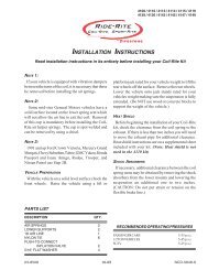
INSTALLATION INSTRUCTIONS<br />
Congratulations - your new Air Helper Springs are quality<br />
products capable of improving the handling and comfort of<br />
your vehicle. As with all products, proper installation is the<br />
key to obtaining all of the benefits your kit is capable of<br />
delivering. Please take a few minutes to read through the<br />
instructions to identify the components and learn where and<br />
how they are used. It is a good idea to start by comparing the<br />
parts in your kit with the parts list below.<br />
The heart of the air spring kit is, of course, the air helper<br />
springs. Remember that the air helper springs must flex and<br />
expand during operation, so be sure that there is enough<br />
clearance to do so without rubbing against any other part of<br />
the vehicle.<br />
Be sure to take all applicable safety precautions during the<br />
installation of the kit. The instructions listed in this brochure<br />
and the illustrations all show the left, or driver’s side of the<br />
vehicle. To install the right side assembly simply follow the<br />
same procedures.<br />
PARTS LIST<br />
AIR SPRING 6397 2<br />
UPPER BRACKET 5492 2<br />
UPPER FRAME BRACKET 5491 2<br />
LOWER BRACKET 5494 2<br />
CLAMP BRACKET 5493 2<br />
BRACKETSTRAP 5086 4<br />
3/8"-16 X 1" HEX HEAD BOLT 8<br />
3/8"-16 FLANGE NUT 16<br />
5/16"-18 X 1" HEX HEAD BOLT 4<br />
5/16"-18 FLANGE NUT 4<br />
3/8"-16 X 3/4" HEX BOLT 2<br />
3/8"-16 X 4-1/2" CARRIAGE BOLT 8<br />
This kit includes inflation valves and air lines for each air<br />
spring. This will allow you to compensate for unbalanced<br />
loads. If you would rather have a single inflation valve<br />
system to provide equal pressure to both air springs, your<br />
dealer can supply the optional "T" fitting.<br />
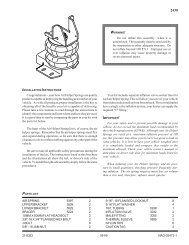
IMPORTANT!<br />
For your safety and to prevent possible damage to<br />
your vehicle, do not exceed the maximum load<br />
recommended by the vehicle manufacturer (GVWR).<br />
Although your Air Helper Springs are rated at a maximum<br />
inflation pressure of 100 psi, this pressure may allow you<br />
to carry too great a load on some vehicles. It is best to<br />
have your vehicle weighed once it is completely loaded<br />
and compare that weight to the maximum allowed. Check<br />
your vehicle owner’s manual or data plate on driver side<br />
door for maximum loads listed for your vehicle.<br />
When inflating your Air Helper Springs, add air<br />
pressure in small quantities, checking pressure frequently<br />
during inflation. The air spring requires much less air<br />
volume than a tire and, therefore, inflates much quicker.<br />
TOOLS REQUIRED<br />
• HACK SAW<br />
• (2) 1 1/8" END WRENCH<br />
• (2) 9/16" ENDWRENCHES • (2) 1/2" END WRENCHES<br />
• 5/16" DRILL BIT • 3/8" DRILL BIT<br />
• 1/8" DRILL BIT • ELECTRIC DRILL<br />
• UTILITY KNIFE OR RAZOR BLADE<br />
3/4"-16 X 1 3/4" HEX BOLT 2<br />
3/4" LOCK WASHER 2<br />
3/4" FLAT WASHER 4<br />
3/4"-16 HEX NUT 2<br />
5/8"-18 JAM NUT 2<br />
5/16" FLAT WASHER 4<br />
18 ft. TUBING 0938 1<br />
INFLATION VALVE 3032 2<br />
AIR FITTING 3048 2<br />
NYLON TIE WRAP 7<br />
CAUTION TAG 2<br />
THERMAL SLEEVE 2<br />
21-8323 07-06 NAD-34990-1
AIR<br />
FITTING<br />
5/8” - 18<br />
NYLON<br />
JAM NUT<br />
2407<br />
CLAMP<br />
INSTALLATION<br />
FRAME<br />
5/16”-18<br />
FLANGE NUT<br />
CLAMP<br />
UPPER<br />
BRACKET<br />
3/4” -16 x 1 3/4”<br />
HEX BOLT<br />
AIR SPRING<br />
JOUNCE<br />
BUMPER<br />
BRACE<br />
5/16” -18 x 1”<br />
HEX BOLT<br />
UPPER<br />
BRACKET<br />
KIT TO FRAME ASSEMBLY<br />
LOWER<br />
BRACKET<br />
LARGE FLAT<br />
WASHER<br />
3/4" X 1 3/4"<br />
BOLT<br />
LARGE FLAT<br />
WASHER<br />
FOR CLAMP<br />
INSTALLATION,<br />
SEE INSERT.<br />
3/8” -16 x 3/4”<br />
HEX BOLT<br />
LOCK<br />
WASHER<br />
3/4" NUT<br />
3/8” -16<br />
FLANGE NUT<br />
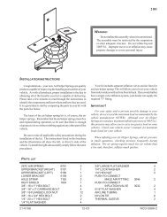
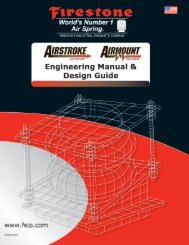
FIGURE "A"<br />
UPPER<br />
FRAME<br />
BRACKET<br />
3/8” -16 x 1”<br />
HEX BOLT<br />
LEAF STACK<br />
3/8”-16 X 4-1/2”<br />
CARRIAGE<br />
BOLTS<br />
K<br />
IT<br />
A<br />
SSE<br />
M<br />
BLY<br />
NOTE: Both illustrations are of<br />
AXLE<br />
JOUNCE<br />
BUMPER<br />
CUT LINE<br />
the right, or passanger’s side, of the<br />
truck. Refer to step 3 for the proper<br />
lower bracket alignment. Repeat<br />
instructions for driver’s side installation.<br />
FRONT<br />
WHEEL<br />
3/8" - 16<br />
FLANGED<br />
LOCK NUTS<br />
BRACKET<br />
STRAP
U-BOLTS<br />
AIR<br />
SPRINGS<br />
AIR LINE<br />
CUT<br />
LINE<br />
PUSH-TO-CONNECT<br />
INFLATION VALVE<br />
BODY OF<br />
VEHICLE<br />
Figure "C"<br />
Figure "B"<br />
BUMPER<br />
Figure "D"<br />
AIR HOSE<br />
FLAT WASHER<br />
HEX NUT<br />
VALVE CAP<br />
JOUNCE<br />
BUMPER<br />
INFLATION<br />
VALVES<br />
AXLE<br />
LEAF STACK<br />
NOTE:<br />
Please read thorough this manual completely before<br />
installing the air spring kit to your vehicle.<br />
STEP 1 - PREPARE THE VEHICLE<br />
With the vehicle on a solid, level surface chock the front<br />
wheels. Remove the negative battery cable. Raise the<br />
vehicle by the axle and remove the rear wheels. After the<br />
removal of the wheels lower the vehicle so the axle rests on<br />
jack stands rated for your vehicles weight. With a hack saw,<br />
cut the jounce bumper located under the frame rail even<br />
with the U-bolts, refer to Figures "A" and "B".<br />
STEP 2 - PRE-ASSEMBLE THE KIT<br />
Select a lower bracket from the kit and one air helper spring from<br />
your kit. Attach the lower bracket to the air spring using a 3/8-16 x<br />
3/4" hex bolt, see Figure "A". Next, select an upper bracket from<br />
the kit and install the upper bracket to the air spring using 5/8" jam nut.<br />
Install the air fitting into the air spring. Tighten the air fitting securely to<br />
engage the orange thread sealant, see Figure "A".<br />
STEP 3 - INSTALLING THE ASSEMBLY TO THE VEHICLE<br />
Place the assembly on top of the leaf stack centered over the axle,<br />
see Figure “A”. Attach the upper frame bracket to the upper bracket<br />
with the four 3/8"-16 X 1" hex bolts and hex nuts. Be sure to position the<br />
upper frame bracket so the large hole lines up over the large hole on the<br />
frame. Install the 3/4”-16 x 13/4” hex head bolt, 3/4" washers, 3/4" lock<br />
washer, and 3/4”-16 hex nut in the lager hole. Next, install the clamp<br />
bracket over the jounce bumper brace and attach it to the upper bracket<br />
with two 5/16"-18 X 1" hex bolts and nuts. See Figure "A". Once the<br />
position of the upper bracket is fixed, place the 3/8"-16 X 41/2" carriage<br />
bolts into the square holes in the lower bracket. Place the bracket straps<br />
under the leaf spring and attach them to the carriage bolts with the 3/8"<br />
flange lock nuts. See Figure "A".<br />
STEP 4 - INSTALLATION OF THE PASSENGER'S SIDE ASSEMBLY<br />
Follow steps 1-3 with reverse orientations for assembly and installation of the passenger's side assembly.<br />
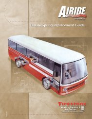
STEP 5 - INSTALL THE AIR LINE AND INFLATION VALVE<br />
Uncoil the airline tubing and cut it into two equal lengths. DO NOT FOLD OR KINK THE AIRLINE TUBING.<br />
Try to make the cut as square as possible. Insert one end of the airline tubing into the air fitting installed in the top<br />
of the air helper spring. Push the airline tubing into the fitting as far as possible. Select a location on the vehicle for<br />
the air inflation valves. The location can be on the bumper or the body of the vehicle, as long as it is in a protected<br />
location so the valve will not be damaged, but maintain accessibility for the air chuck see Figure "C" on the next<br />
page. Drill a 5/16" hole and install the air inflation valve using two 5/16" flat washers per valve as supports see<br />
Figure "D". Route the airline tubing from the air helper spring to the valve, avoiding direct heat from the engine,<br />
exhaust pipe, and away from sharp edges. Thermal sleeves have been provided for these conditions. The airline<br />
tubing should not be bent or curved sharply as it may buckle. Secure the airline tubing in place with the nylon ties<br />
provided. Push the end of the airline tubing into the inflation valve as illustrated, see Figure "D".
STEP 6 - CHECK THE AIR SYSTEM<br />
Once the inflation valves are installed, inflate the air helper springs to 70 psi and check the fittings for air leaks.<br />
Using a spray bottle, apply a solution of soap and water to the fittings. If a leak is detected at a airline tubing<br />
connection then check to make sure that the airline tube is cut as square as possible and that it is pushed completely<br />
into the fitting. The airline tubing can easily be removed from the fittings by exhausting all the pressure in the air<br />
springs and then pushing the collar towards the body of the fitting and then, with a gentle pull, remove the airline<br />
tubing. Reinstall the tubing and reinflate the air springs and check for leaks as noted above. If a leak is detected<br />
where the air fitting screws into the spring and tighten the air fitting into the air spring until the leak stops.<br />
This now completes the installation. Install the wheels and torque the lug nuts to the manufacturer's specification.<br />
Raise the vehicle by the axle and remove the jack stands. Lower the vehicle to the ground. Reattach the negative<br />
battery cable and remove the wheel chocks from the front wheels. Before proceeding, check once again to be<br />
sure you have proper clearance around the air springs. With a load on your vehicle and the air helper springs inflated,<br />
you must have at least 1/2" clearance around the air springs. As a general rule, the air helper springs will support<br />
approximately 50 lbs. of load for each psi of inflation pressure (per pair). For example, 50 psi of inflation pressure<br />
will support a load of 2500 lbs. per pair of air helper springs. FOR BEST RIDE use only enough air pressure in<br />
the air helper springs to level the vehicle when viewed from the side (front to rear). This amount will vary depending<br />
on the load, location of load, condition of existing suspension and personal preference.<br />
NOTE:<br />
Too much air pressure in the air helper springs will result in a firmer ride, while too little air pressure will allow<br />
the air helper spring to bottom out over rough conditions. Too little air pressure will not provide the improvement<br />
in handling that is possible. TO PREVENT POSSIBLE DAMAGE MAINTAIN A MINIMUM OF 5 psi<br />
IN THE AIR HELPER SPRINGS AT ALL TIMES.<br />
NOTE:<br />
Once the air helper springs are installed, it is recommended that the vehicle not be lifted by the frame,<br />
as over-extension may occur, resulting in damage to the air helper springs. However, should it become<br />
necessary to raise the vehicle by the frame, deflate both air helper springs completely.<br />
NOTE:<br />
MIN PRESSURE<br />
5 PSI<br />
MAX PRESSURE (LOADED) 100 PSI<br />
www.ride-rite.com