MINI MCR-SL-UI-REL(-SP) - Onlinecomponents.com
MINI MCR-SL-UI-REL(-SP) - Onlinecomponents.com
MINI MCR-SL-UI-REL(-SP) - Onlinecomponents.com

Create successful ePaper yourself
Turn your PDF publications into a flip-book with our unique Google optimized e-Paper software.
<strong>MINI</strong> <strong>MCR</strong>-<strong>SL</strong>-<strong>UI</strong>-<strong>REL</strong>(-<strong>SP</strong>)<br />
Power Supply<br />
Configuration<br />
Supply via the <strong>MINI</strong> Analog Module<br />
Where the total current consumption of the aligned <strong>MINI</strong><br />
Analog modules does not exceed 400 mA, the power can<br />
be supplied directly at the connection terminal blocks of one<br />
<strong>MINI</strong> Analog module. A 400 mA fuse should be connected.<br />
Supply Using a Power Terminal Block<br />
The <strong>MINI</strong> <strong>MCR</strong>-<strong>SL</strong>-PTB power terminal block (Order No.<br />
2864134) or the <strong>MINI</strong> <strong>MCR</strong>-<strong>SL</strong>-PTB-<strong>SP</strong> power terminal<br />
block (Order No. 2864147), which are the same shape, are<br />
used to supply the supply voltage to the DIN rail connector.<br />
A 2 A fuse should be connected.<br />
Supply Using System Power Supply Unit<br />
(Not for Zone 2)<br />
The <strong>MINI</strong>-SYS-PS-... system power supply unit (Order No.<br />
2866983) with 1.5 A output current connects the DIN rail<br />
connector to the supply voltage and can thus be used to<br />
supply several <strong>MINI</strong> Analog modules from the mains.<br />
Diagnostics<br />
Never connect the supply voltage directly to<br />
the DIN rail connector.<br />
It is not permitted to draw power from the<br />
DIN rail connector or from individual <strong>MINI</strong><br />
Analog modules.<br />
The yellow LED on the front of the device (3 in Figure 1 on<br />
page 3) indicates that voltage is applied to the PDT relay<br />
coil, i.e., that the relay has switched.<br />
The red LED on the front of the device (4 in Figure 1 on<br />
page 3) indicates the following error states:<br />
– LED ON: Measured value overrange > 102.5%<br />
– LED flashing: Module faulty<br />
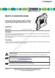
Setting the Switching Thresholds<br />
The potentiometer 5, which can be used to set the<br />
switching thresholds, is located under the transparent<br />
cover.<br />
Figure 6<br />
Electrostatic discharge<br />
The module contains <strong>com</strong>ponents that can be<br />
damaged or destroyed by electrostatic<br />
discharge. When handling this module, observe<br />
the necessary safety precautions against<br />
electrostatic discharge (ESD) according to<br />
EN 61340-5-1 and EN 61340-5-2.<br />
Potentiometer and DIP switches<br />
DIP Switches<br />
DIP switch S1 (! in Figure 6) can be used to specify the<br />
input signal range, switching hysteresis, the relay pickup/<br />
relay dropout delay, and to switch between operating<br />
current/closed circuit current behavior.<br />
DIP S1<br />
Input<br />
1 2<br />
0 V ... 10 V<br />
• • 0 mA ... 20 mA<br />
• = ON<br />
online<strong>com</strong>ponents.<strong>com</strong><br />
<strong>MINI</strong> <strong>MCR</strong>-<strong>SL</strong>-<strong>UI</strong>-<strong>REL</strong><br />
5<br />
1<br />
on<br />
S1<br />
off<br />
!<br />
Ord.-No.: 28 64 48 0<br />
Switch<br />
DIP S1<br />
Switching Hysteresis<br />
3 4<br />
0.1%<br />
• 1.0%<br />
• 2.5%<br />
• • 5.0%<br />
• = ON<br />
102132_02_en PHOENIX CONTACT 6