pdf version - The Old Car Manual Project
pdf version - The Old Car Manual Project
pdf version - The Old Car Manual Project

You also want an ePaper? Increase the reach of your titles
YUMPU automatically turns print PDFs into web optimized ePapers that Google loves.
BREATH 8l<br />
Right Side - Wau kesha Mo d e l 19 0 -G l - GlB<br />
left Side - Wau kesha Mod e l 19 0- G l - GlB
~ f5l<br />
e<br />
~ t FLYWHEEL<br />
T IM ING<br />
MARK<br />
II<br />
)<br />
I'<br />
I:<br />
Right Side - Waukesha M odel 180 -G L - GLB<br />
Left Side - W au kesha M ode l 180-GL - G LB
4 WAUKESHA MODELS 190 , 185 , 180<br />
CONTENTS<br />
PAGE<br />
DESCRIPTION 5-7<br />
General _____________ ________ 5<br />
Crankcase 5<br />
Crankshaft 6<br />
Bearings 6<br />
Governor 6<br />
Ignition 7<br />
<strong>Car</strong>buretion 7<br />
Water Pump 7<br />
Oil Pump 7<br />
LUBRICAT10N 8-13<br />
Oil Quant ity 8<br />
Oil Changes 8<br />
Selecting Oil Viscosity<br />
Oil Temperature Method 8<br />
Estimated Oil Temp. 9<br />
Additive Type Oils 9<br />
Special Industrial Service 10<br />
Accessory Lubrication 10<br />
Oil Filters 10<br />
Oil Pressure Control 11<br />
Oiling System 11<br />
Rocker Arms 13<br />
COOLING SYSTEM 14-17<br />
Anti-Freeze 14<br />
Cooling System Capacities 14<br />
<strong>The</strong>rmostat Removal 14<br />
<strong>The</strong>rmostat Testi ng 15<br />
Cleaning Cooling System 15<br />
Commercial Cleaners 16<br />
Cooling Fans 16<br />
Fan Belts 16<br />
Replacing Fan Belts 16<br />
Air Cleaners :...___ 17<br />
SERVICE ADJUSTMENTS 18-25<br />
Ignition 18<br />
PAGE<br />
Distributor Timing 19<br />
Magneto 20<br />
Magneto Maintenance 21<br />
Magneto Timing ~ - - - - - 21<br />
Valve Clearance Adju stment 22<br />
Resetting the Governor 22<br />
Gasoline <strong>Car</strong>buretors 23<br />
<strong>Car</strong>buretor Adju stments 24<br />
Gas-Fuel Con<strong>version</strong> 24<br />
Volume Tanks 25<br />
REPAIR AND OVERHAUL 26-33<br />
Disassembly 26<br />
Oil Pan Removal 26<br />
Cylinder Sleeve Removal 27<br />
Camshaft 27<br />
Cam Followers 28<br />
Valve and Mechanism- Repair __ 28<br />
Compression Checks 29<br />
Valve Mechanism ._ 29<br />
Guides and Seats 29<br />
Valve Gri nding 30<br />
Hand Gri nding 30<br />
Seat Insert Replacement - - - - - - -31-33<br />
REASSEMBLY 34-40<br />
Installing Cylinder Sleeves 34<br />
Cylinder Head Gasket Crush 35<br />
Piston Fitting 35<br />
Bearing Ad justment 37<br />
Side Clearances 38<br />
Running Clearance 38<br />
Replacing Cylinder Head 39<br />
Flywheel Alignm ent 40<br />
CLEARANCES AND L1MITS 41-4 5<br />
Model 190 41<br />
Model 185 43<br />
Model 180 43
WAUKESHA MODELS 190, 185, 180<br />
5<br />
DESCRIPTION<br />
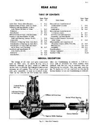
GEN ERA L<br />
T he Waukesha 190, 185, 180 series engines are of overhead valve, wetsleeve<br />
construc t ion, all incorp orating the sa me gen era l design fea tures. <strong>The</strong><br />
190 and 185 models are six-cylinde r engines; the 180 model is a fo ur-cylinder<br />
engine.<br />
DDI ENSIONS<br />
BORE AN D STROKE CYL. D ISPLACDIENT<br />
190G L - GLB<br />
180GL - GL B<br />
185 G L -GLB<br />
3.75 x -I<br />
3.5 x 3.75<br />
3.5 x 3.75<br />
6<br />
4<br />
6<br />
265 Cubic inches<br />
144 Cubic inch es<br />
216 Cubic inch es<br />
<strong>The</strong>se engines are desig ned to give exte nde d se rvice life witho ut specialize<br />
d or unusua l mainte nance t ech niq ues. Clean oil in th e proper qu antity ;<br />
cle an, so ft, cooling water; and r eg ular attenti on to such it ems as air cle aners ,<br />
spark plugs, fue l st rainer s, and oil filt er s wi ll in sure continue d reliable<br />
perform an ce.<br />
CRANKCA SE<br />
For maximum rigidi ty and accurate be aring al ignment, t he crankcase<br />
and cylinder block is cast as a single unit. Bearing cr oss walls and wate r<br />
ba ffle s are ge nerous ly fillet ed and he avy top diap hrag ms and bottom<br />
Left Side - Cron kease, 190-GLB
6 WAUKESHA MODELS 190 , 185, 180<br />
flanges locat e and s up port the cylinder sleeves . <strong>The</strong> slee ves are exposed<br />
to cooling water for practically their en t ire length a nd are sealed w ith<br />
two r ubber ring s at t he lower end an d the cy linder head g asket at the<br />
top. 1(0 specia l tool s are need ed fo r in stallatio n or removal o f these sleeves.<br />
CRANKSHAFT<br />
<strong>The</strong> crankshafts used in the 190. 185 and 180 series engines a re heat<br />
treated and p recision g round steel io rgings. <strong>The</strong>se shaf ts are iully bala nced<br />
both sta t ica lly and dynamically. T he m irror fin is hed crankpins a nd main<br />
bearing journals are hel d to ex t re melv close tol erances t o acco m moda te<br />
precis ion bearing s hells w it ho u t the nec essity for field fitt in g.<br />
I t is im portant t hat t he owner be acq ua int ed with the se ve ra l types of<br />
cra nks hafts iro m the st a ndpoin t oi orde r in g se rvice p arts. A ll crankshafts<br />
u sed in r ecen t Model 190 oil field engines a re drilled ior pressur e lubrication<br />
to the co nnec t ing rod lo w er end bearings. O t he r 190 series engines are<br />
eq uip pe d w it h a metered jet luhrication syst em and incorporated oil transf er<br />
r ecesses in the main b earing journal s but are not drilled . This is discussed<br />
under oiling system.<br />
A ll cra n ks hafts used in the 185 and 180 ser ies engines a re eq uippe d with<br />
oi l transfer recesses for m et ered jet lubrica t ion. C u r re n t production Model<br />
180 engin es em p loy counterba lanced sha its wi t h 2)i" diameter crankpins.<br />
A very la rg e n umber of engines have, how ever , been built with a co nvent<br />
io nal crankshaft a nd 2" diamet er crankpins. It is possible to convert an<br />
ea rl ie r eng ine at ti me oi overhaul to a cc o m m odat e a co u nterhalanced sha ft .<br />
b ut t h is change will probably r eq uire some minor reworkin g oi the cran k<br />
ca se for clearance. pl us re p lacem ent oi the con nect ing rods. pistons. id ler<br />
gear sha ft , and the idler gear hushing s upport.<br />
BEARIN GS<br />
Preci sion type copper-lead m a in and connecting rod hear ings p erm it<br />
field replacement when need ed without line horing. <strong>The</strong> flang ed u pper and<br />
lower halv es' oi the ce nter main hearing absorbs thrust lo a ds on the 180<br />
m od el a n d since it is al so of the<br />
prec ision type, no specia l endplay<br />
adj ustment s are required.<br />
<strong>The</strong> sa me thing applies t o the<br />
# 3 bearing s in the 185 and 190<br />
engines. Steel-backed, bab bittlined<br />
bushing-s s up por t both the<br />
gear end oi the ca mshaft and the<br />
id ler g-ear sha it . Piston pin s are<br />
full-floating- in a diamond-bored<br />
bronze b ushing in the connecting<br />
rods.<br />
GOVERNOR<br />
A se lf -co nta ined, g earvdriven<br />
governor is mounted within the<br />
gear cove r and a sm a ll proj ect-<br />
Sectional View -<br />
Gove rno r
WAUKESHA MODELS 190, 185, 180 7<br />
ing hou sin g . This governor is of the fa miliar two- weig ht, centrifugal ty pe,<br />
and req ui re s no adjustment other t han establishing th e desired high idl e<br />
speed. A screw type surge adjustment is al so provided .<br />
IGNITION<br />
Ignition may be with eithe r a fixed-timing. vertically or flange-mounted<br />
magnet o. or with a di stributor and coil. \ Yith the except ion of the flangemounted<br />
magnet o. used on Model 190 oil field eng ines and which is driven<br />
fr om the engine gear t ra in , th e ig nition unit is drawn by a spline and key<br />
on th e oil pump drive sha ft upper enc!' Adjustment a nd timing of these units<br />
are discussed under D I STR IB UT O R T BIIK G. or. MAGKETO THd ING.<br />
CARBURETION<br />
F or use wi th gaso lin e or kerosen e, a standard diaphragm-type fuel<br />
p ump is used and driven from an eccentric on the camshaft. <strong>Car</strong>buretors<br />
may be for gas only, for gasoline only, or of the gas-gaso line type as<br />
specified. <strong>Car</strong>b uretor adj ustm en ts are discussed un der a separate heading.<br />
WATER PUMP<br />
T h e water pump requires no special lubrication , packing or attention<br />
du ring it s ser vice lif e. An internal seal is used in combination wi t h a unittype<br />
ball bearing a nd p ump shaf t to provide a simple, rugged ly constructed<br />
water pump.<br />
Water Pump<br />
OIL PUM P<br />
A high-capacity, spring-loade d va ne -type pu mp. driven by a sp iral gear<br />
fr om the ca ms haft provide s oil uncler pressure to th e lubricating syst em of<br />
the 190. 18j a nd 180 eng ines, This pump is of \'ery simple. rugg ed constr ucti<br />
on s ince th e only movi ng parts a re the drive sha ft a nd t wo vanes. <strong>The</strong><br />
oil inl et screen is sus pe nde d from the oil inlet pipe in such a manner as to<br />
float fr eely and p ick up th e clean oil from the s urf ace of the supply in the<br />
oil pan. In recent Model 190 oil field eng ines w ith t he main bearing oil<br />
g rooves in both upper and lo wer in sert s, a gea r type oil pump is used .
8 WAUKESHA MODELS 190, 185, 180<br />
OIL QUANTITY<br />
LUBRICATION<br />
<strong>The</strong> oil capacities of the eng ines in this series a re listed in the tabular .<br />
data in the back of this manual. R em ember that the qua nt it ies listed are<br />
for the oil pan. Filters or other extern al devices requiring oil will necessitate<br />
an additional quantity. T o det ermine exactly how much additional<br />
oi l is needed, fill the crankcase w it h the recommended quantity, r un the<br />
engine for a few minutes, and add enoug h oil in a m easured amount to<br />
again bring the level to F ULL on the dipstick. Once the total a mo unt has<br />
been es tab lis hed it may all be poured in at the sa m e time on su bsequ ent<br />
oil changes.<br />
OIL CHANGES<br />
<strong>The</strong> cra nkcase level sh ould be ch ecke d pnor to each day's eng ine<br />
ope ration an d at the sa me time t he co ndit ion of the oil as rev ealed on the<br />
bayonet gauge should b e ob served ca refully. Replace oil at any time it is<br />
plainly diluted, broken down, thickened by s lu dg e, or otherwise deteriorated.<br />
A good r ule is to change it every 50 hours unt il experience shows t hat<br />
the particular oil in use wi ll remain se rviceable for a longer time. \ Vh enever<br />
oil is changed , the filt ers m us t be serviced, If it is desired to use oil<br />
longer than 100 hours of active duty, it is suggested t hat the lubrica tion<br />
engineer of the oil supp lier be consulted. N ot all oils in every type of<br />
engine will give maxim um se rvice, therefore be ca re ful to examine t h e<br />
oi l after the first draining to det ermine whether it is standing up in ser vice.<br />
T rial pe riods of 10 hours are sugg es ted a nd a t the end of such periods<br />
.ma ke careful in sp ection s for sludg ing , fro thing and emulsification. Such<br />
conditions call for more fr equent chang es or a different oil. In winter<br />
operation, low oil temperatures (below 170 degree, F. ) are particularly<br />
likely to cau se slu dg e formation. T emperature cont rol devices-curtains,<br />
shutters and so on-e-sh ou ld be used if n eeded in order to ho ld the oi l<br />
temperature around 180 degrees, F . Butane, natural g as and other fuels<br />
not t endin g . to dilute oil may contribute m aterially to g re a te r oil life if<br />
operating co nditions are suitable.<br />
SELECTING OIL VISCOSITY-OIL TEMPERATURE METHOD<br />
All ot he r thing s suc h as oi l type a n d qua lity be ing eq ua l, t h e principle<br />
factor in choosing the p ro per oil vi scosity is the op erating te mpe rature<br />
of the oil in the crankca se. It is this te mperat ure that establishes the<br />
running vi sc osity of the oil ; hence, the so-calle d O IL TEMPERATURE<br />
method of se lect ing oi l viscos ity will b e explained first.<br />
1. Make one or more check rt111 S under actual op erating co n ditions of<br />
speed and load. Use SA E 20/ 20 'vV oil for this test. Note the temperature<br />
range of the oil in the crankca se by means of an accurate oi l temperature<br />
gauge immersed in the oil.<br />
2. Find the temperature ra.nge noted in the ab ove test in the tabulation<br />
below. <strong>The</strong> proper oil vi scosity for these op erating conditi ons wi ll be<br />
found directly to the right. If different kinds of se rvice cause the loads<br />
and operating conditions to vary, re-check the oil t emperature as above
WAUKESHA MODELS 190 , 185, 180 9<br />
an d se lect an oil of lighter or hea vier visco sity as required by the new<br />
conditi ons .<br />
. Oi l Opera t ing<br />
Temperatures<br />
210-250° F .<br />
180-210 ° F.<br />
to 180° F .<br />
SA E Vi sc osity<br />
Num be rs<br />
30<br />
20j 20W<br />
lOW<br />
, Vh ere oi ls are required for st a rt ing at low temperature, m ult i-viscosity<br />
oi ls can be used w hich will g ive lo w enough viscos ity for start ing and st ill<br />
provide th e p roper SA E grarl e in dicat ed in th e a bove table for the opera t ing<br />
t emp era ture.<br />
OIL VISCOSITY RECOMMENDATION FOR HEAVY DUTY SERVICE<br />
Heavy du ty se r vice is considered to b e an average load excee ding on e<br />
ha lf max im um engine power . To det er min e t h e correct SA E g ra de of oil<br />
select th e co r re ct SAE oil number fro m the above table af te r m easuring the<br />
cra nkc as e oi l temperature.<br />
LIGHT DUTY SERVICE<br />
L ight duty ser vice is co nside re d t o be a n a verage load not ex ceeding<br />
one -half m aximum eng ine po w er. For engines ope rat ing in light duty se r vic e<br />
a n oil of one SA E g rade ligh ter vi sco sity th a n for hea vy duty ser vice can<br />
be used.<br />
ESTIMATED OIL TEMPERATURE<br />
W hen the act ual opera t ing oil temperature is not known, a n es t im ate of<br />
t he SA E oil g rade to u se can be made by assum ing th e oi l temperature w ill<br />
be 130 degrees abo ve the a ir t em p erature in hea vy duty se rv ice. For example :<br />
A t an a ir tem perature of 70° F, es t ima te d oil t em pe ra t ure wo uld b e 200 ° F.<br />
Use SAE 20j20vV as indicated in the ab o ve table. N ote : This is only an<br />
es ti mate, since the type of in stall ation det ermines the amount of ai r circ ulation<br />
fo r coo ling aroun d the oil pa n . A ct ua l cra nkcase op er ating oil temperat<br />
u res should be m ea sured w h enever po ssibl e.<br />
OPERATING TEMPERATU RES<br />
E ngines operated w it h low oil t empera t ures bel ow 160 dcg . F . can be<br />
ex pect ed t o show excessive s ludg ing a nd wear. E ngin cs op er ated w it h hi g h<br />
oil t empera tures a bove 230 deg. may expe rie nc e lacquering and ring sticking.<br />
<strong>The</strong> undesirab le eff ects of operat in g at abnormall y lo w or h ig h t emperat<br />
ures can b e allevia t ed to som e extent by th e u se of addit ive type oils.<br />
ADDITIVE TYPE OILS<br />
Practica lly a ll oil co mpanies a re ma rk eting additive t ype oils t o m eet<br />
service r eq ui rem ents com mon t o industrial eng in e operation. T he perfo<br />
r ma nce levels of t hese oils under eng inc opera ti ng co n dit ions a re defined<br />
by t he foll o wi ng three military spe cifica t io ns :<br />
M IL- L-2 104A ( F ormerly 1\:1 I L-0 -210 4) Hun w it h 0.35% su lph ur<br />
M IL-L -2104A ( For m erly M] L-0-2104) R un wit h I % sulphur<br />
Su perio r L ubricant (Series 2)
10 WAUKESHA MODELS 190, 185, 180<br />
<strong>The</strong> I n tern al Co mb us t ion E ng ine I nst it ute, 201 N ort h W ell s St re et,<br />
Chicago 6, Ill inois, has pub lish ed a list of oil brand names represented by<br />
. t heir suppliers as m eet in g th e a bove se rvice requ irem ent s. · This list indi<br />
cates the three mi litary spec ificat ions as type s A, 13, and C, respective ly .<br />
(T h is is in no way related to the Waukesha Motor Co mpany's visc osit y<br />
class ification o f eng ine models by E ng ine Class A , B, and C.)<br />
For avera g e heavy du ty industri al service Wauk esh a Motor Company<br />
recommen ds t he usc of type A oils for bot h di esel and car buretor t yp e eng ines.<br />
F or severe service, resu lti ng from extre mely h igh or low op eratin g temperatures,<br />
or for high su lphur fue ls (above 0.5% for diesel fu el ), or fo r ope rat ing<br />
co n dit ions giving ex cess ive pi ston ring co king, Type 13 oils a re recommended.<br />
Type C oi ls should be co nsidered on ly for t he most unusual operating condi<br />
ti ons and after co ns u lt ing t he W aukesha M otor Co mpa ny.<br />
MINIMUM VISCOSITY<br />
T he oil te m pe ra t ure cha rt is arrang ed on the basis of providing a m 1111<br />
mum viscos it y for eac h cla ss of eng ine throug hout th e ope rating temperature<br />
range. T he minim um sta n da rd Saybo lt visc osit ies are 54, 62, a nd 72<br />
for engine Class A, 13, a nd C, resp ectivel y.<br />
SPECIAL INDUSTRIAL SERVICES<br />
Extra precautions are necessa ry to in sure ad eq ua te lubri ca t ion of in dust<br />
rial engines t hat m ust be started after I011g periods at rest or after standing<br />
in a co ld p lace . <strong>The</strong>y sho uld be fille d w ith fre sh wa rm oil a nd r un idle fo r a<br />
few minutes to permit the lubrication system to fill and ensure oil reach ing<br />
all pa rts of t he engine.<br />
ACCESSORY LUBRICATION<br />
M agneto or di st ributor ignition units re quire no spe cial lubricat ion.<br />
Occas ional application of a very sm all qua nt it y of lig ht oil or petroleum<br />
jell y to t he breaker cam wi ll be helpful in red ucing wear on the breaker<br />
point ca m sho e.<br />
O ther a~c e s sories su ch as ge ne ra to rs, and star te rs sho u ld be lub ricated<br />
in accordanc e with their manufacturer's recommendati on s. Ordinarily , a<br />
drop or t wo of light engine oil in t he oil cups is ad equ ate for long pe riod s<br />
of operation. Over-o iling is usua lly ha rm ful to electrica l devices.<br />
OIL FILTERS<br />
A lt hough som e variations may appear in the oi l-filter in stallations used<br />
on t h ese engine s, the same g en eral principl es of maintenance apply to most<br />
of t he m . I n all cases the manufa cturer 's recommendations ac compa nyin g<br />
the filter, or the inst ruction la bel app lied to the side of the filt er should be<br />
followed carefully. <strong>The</strong> filt ers so metimes s upplied w it h the engine as it<br />
lea ves t he fac tory a re re p laced as compl ete units by u nscrew in g t he can-like<br />
ca rtridges fro m t he base mounting on t he engine .<br />
When a filter is provi de d with a p rop erly fu nctioning by -pass va lve ,<br />
th e bl ocking off of the filt er by dirt w ill no t sta rve th e engine of oi l ; on t he<br />
other ha nd, dirt like that blocki ng t he filt er is t he n p ro ba bly passing through<br />
the bea ring s.
WAUKESHA MODElS 190, 185, 180 11<br />
Because of the abo ve possibility , th e recommendation s for filt er ch ang es<br />
coincide w ith re commendations for oil change. If the oil shows evidence of<br />
sludge formation or improper filt er op era t io n, it should be cha ngeel and t he<br />
filter ele m ent as w ell. A lso a che ck shou ld b e made t o see that t he oil a nd<br />
water temperatures a re within the desi red rang e.<br />
If ex perie nce in dicates th e practica bility of running lubri cating oil for<br />
maximum p er iods bet w een ch an g es. t he n t he filt er s may be co nsidered as<br />
sa tis fac tory for this period of operat io n. Tn a ll cases t he filter ele me nts shou ld<br />
be cha ng ed at t he time of oil cha nge.<br />
OIL PRESSURE CO NTROL<br />
U nde r a ll no rmal condition s th e van e or gea r typ e oil pump w ill provi de<br />
adequ a t e oil pressure . In th ose cn gines using t h e va ne type pump, 25-30 Lbs.<br />
is the no rmal running pressure. In Mod el 190 oil fi eld eng ines using full <br />
g roove bearings with t he g ear type pump an d t he st ifTcr relief valve spring ,<br />
40 Lbs. oil pressure is norm a l. <strong>The</strong> oil press ure g a uge should be no ted imm<br />
ed ia t ely u po n starting t he cnginc and shou ld in dicate pressure w it h in at<br />
least 30 seconds, A ho t eng inc will norm ally have a lo w p ressure at idle<br />
speeds . A cold en g ine normally sho ws a high oil pressure until warmed up.<br />
If, wit h th e proper g rade o f oil and the eng ine warmeel up and running at<br />
normal govern ed speed, th e oil p ressure is unusually hig h or low, the followin<br />
g co r rect ive measures may be tricd :<br />
1. Clean t he re lief valve, spring, se a t, and passa g e of dirt a nd ca rbon.<br />
2. Check oil temperature, and co ndit ion of oil.<br />
3. If the reli ef va lve sp ring and th e oil are in good co ndit ion, be sure to<br />
ch eck t he pressure g auge a nd it s co nnect ions before going furt her.<br />
4. A co m mon source of lo w oil pressure is clog g in g of t he oil pump intake<br />
sc reen w ith sludg e a nd ca rbo n . R em o ve such dep osi ts w it h lacquer thinner<br />
or ot her so lve nt.<br />
S. U nusual looseness, g roo ving o r damag e to the main bea ring s o r oil<br />
pu mp w ill a lso ca use lo w oil pressure. S uch co ndit io ns ca ll for re p lace me nt<br />
of wo r n parts.<br />
6. Occasio na lly it may be desirable to inc rease th e relief va lve spring t en sio n<br />
by in sert ing one or t wo washer's behind it.<br />
7, Use of full circ ular g ro O\'cd bcari ng s in t he 190 cn gines in con ju nct io n<br />
wit h t he van e type oil pum p is not rccommcn dcd a nd may ca use lo w oil<br />
p ressure.<br />
OILI NG SYSTEM<br />
<strong>The</strong> o iling sys t em em ploycd o n th e Mod el 190 oil fi eld engines provides<br />
full oil press ure to th e cra nksha ft hcaring s a nd rods. th cn m et cring this oil<br />
s upply throu gh sma ll pockets in th e cra nk journals t o th e accesso ry gears<br />
a nd va lve m echanism.<br />
O il ente rs th e va ne or gear pu m p t hrough th e floa ting oil screen which<br />
p icks up from th e cleaner upper surface of the oil supply . Leaving the
12 WAUKESHA MODELS 190, 185 , 180<br />
Sectional View -<br />
Va ne Type Oil Pump<br />
pressure side of t he pump va ne. the oi l passes up ward through a pa ssage in<br />
the p ump support a nd is fo rced into th e main oil galle ry extending t he len gth<br />
of th e right side of the eng ine .<br />
Metered Jet Lubrication Schematic<br />
At t he fro nt of t he gallery (gcarcov<br />
er end ) a pressu re relief va lve<br />
of th e non-adjustable type prev ents<br />
exc essive pressure build-u p. Drilled<br />
pa ssages co n duc t t he oi l from the<br />
gallery to t he main bearing s. T h e<br />
fran t a nd rear main bea ring cra nkshaft<br />
journals are provided with<br />
small po cke ts w h ich a re so aligned<br />
as to index with t he in coming oi l<br />
passag e a nd bridg e across the journal<br />
to an outgoin g oil pa ssage. This<br />
happens for a brief portion of each<br />
revolut ion of th e shaft. Thus, th e<br />
pressure oil is fed across to a second<br />
oil pa ssa g e in a metere d vo lum e<br />
for distri bution to ot her locations<br />
descr ib ed below .<br />
O il leaving t he fron t main bearin<br />
g through th e passage syste m<br />
described above is co nducte d in<br />
part to a small jet just above the<br />
ca m sha ft drive g ea r. This oil flood s<br />
t he m eshing surf aces of the cra nksha<br />
ft g ear, ca m g ea r, and governor<br />
drive g ear. Part of this oil al so<br />
lubricates the governor shaft bush <br />
ing vi a a drill ed connecting passage.<br />
A bran ch of t hi s pa ssa g e is<br />
blanked off at a loca t ion for an<br />
id ler g ear.<br />
A m et ered jet lubrication sys te m<br />
is used in ot he r 190, 180 and 185
series eng ine s - oi l from the intermediate<br />
m ain he aring m e t ering<br />
slots is co nd ucted to t he second<br />
g alle ry ex te nding th e lengt h of t he<br />
eng ine . This gallery has sm all jet s<br />
located dir ectly above the oil hol es<br />
in t he upper flanks of the co n ne cting<br />
rod bea ring s whe n the co n<br />
necting rods a re in the prop er<br />
posit ion to receive lubrication . T he<br />
out let s, or je ts, meter t h e correct<br />
am ount of oil into eac h of the rod<br />
bea rin g s. Because of the met ering<br />
effect of both th e ro ta t ing crank <br />
sh aft a nd t he jet s. oil supply to the<br />
co nnect ing rod bea ring s and cy linder<br />
walls is not aff ect ed by w ea r<br />
of t he rod bearings as may occur<br />
whe n fu ll pressure is used to these<br />
parts.<br />
WAUKESHA MODELS 190, 18 5 , 180 13<br />
o<br />
Schema tic - O il Pa ssages in<br />
Front of Cro n kca se<br />
Oi l lea ving t he o ut let ho le of t he rear main bearing eac h time t he p ock et s<br />
in th e crank journal index. passe s up wa rd t hrou gh dri lled passag es in the<br />
. cra nkcase a nd cy linder head to a tube fitt in g on th e head. From this fit ti ng<br />
oil passes to the hollow rocker ar m sha ft and t hen t o eac h rock er arm in<br />
t urn to p ro vide co nt ro lled o iling of t he rockers, va lv es, an d g u ides.<br />
A fter lubricating t he ro cker a nd valve m echa nism t he oil feeds ba ck<br />
by g ravity to th e space a round th e push ro ds an d on clo w n to th e tappet<br />
compartment where it is co lle ct ed in a la rg e g a lle ry located just above t he<br />
camshaft. Drilled ho les met er t he oil a nd permit it to flow downward a nd<br />
supply the cam jo urn al with oil.<br />
ROCKER ARMS<br />
R ecent produ ction eng ines o f t he model 180. 185 an d 190 se ries a re b u ilt<br />
wit h rocker a r ms incorpora t ing oil<br />
~ J "<br />
ho les off set 30° from the former<br />
~<br />
. ~<br />
vertical po sit ion as sho wn in the<br />
accompany ing illu s t r a t ion. N o<br />
• 1<br />
ch a nge wa s mad e in t he ro ck er<br />
arm sha ft.<br />
Se rv ice rocker arm s will also<br />
change t o t he la test type and atte<br />
ntion is ca lle d to the fact that<br />
although t he two rocker arm types<br />
can be in tercha ng ed in complet e<br />
sets on a ny eng ine, th e old a nd<br />
the ne w t ypes sho uld n ev er he<br />
m ix ed to gether a nd used on th e<br />
...<br />
sa me engine . A ttempts to use both<br />
ROCKER ARM OIL HOLE<br />
types of ro ckers on t he same engine
14 WAUKESHA MODELS 190 , 185, 180<br />
w ill serio us ly disturb t h e lu brica t ion. ln addi tion, th e olde r type rocker wa s<br />
lubrica ted throu gh a pressu re lin e fitt ing wi th a re lief ho le. If a chang e<br />
over to a set of ne w rocker arms is mad e, the rclicved fitting sho uld be<br />
replaced with a sta ndard undrilled fitting.<br />
I dentification of the t w o rocker designs is readi ly made by the st raightt<br />
hrough drilling of the oil pa ssag e through the bush ing in the ea rl ier ro cker.<br />
If no bushing is in the rocker, it will be possible to make id entificat ion by<br />
inspecting for t he short ra dial groov e exten ding from th e t op oil hole around<br />
the in ner bore for 45° in t he new ro ckers.<br />
COOLI NG SYSTEM<br />
U nder normal co n dit ions, th e heat sen sit ive t hermostat in the water<br />
o ut let w ill maintain t empera t urcs within the desir ed limi ts o f 170° t o 180° F .<br />
D uring co ld w eather it may be necessary to cover part of t he ra diator arca<br />
t o hold t hese lim it s and pre ven t co nde ns at ion and engin e w ear. Use clean,<br />
soft wat er on ly.<br />
ANTI-FREEZE<br />
W hen adding anti-freeze, mea sure the capacity of the entire cooling<br />
system; then add an ti-f rceze on a percenta g c basis ac cordin g to the low est<br />
anti cipated tem perat ure. <strong>The</strong> follo wing tabl e may be used for calcula t ing<br />
the amou nt of anti -freeze needed.<br />
Radi at or F reezes at<br />
Pure Mcthyl Denatured \ \f ood Ethyle ne Glycol<br />
Glycer inc D eg rcc s<br />
W ood Alco ho l Alcoho l (..Prcston c" )<br />
( G.P. A.) F. C.<br />
13% 17% 16% 37% + 20 - 7<br />
20% 26% 25% 55% + 10 - 12<br />
27% 34% 33% 70% 0 - 18<br />
32% 40% 39% 81% - 10 -23<br />
37% 46% 44% 92% -20 - 29<br />
40% 53% 48% 100% - 30 - 35<br />
To prevent rust w he n usi ng st raig ht a lcohol a nd water solut ions . a nd<br />
when using water alo ne, add one o unce of soluble oil for cvc ry gallon of<br />
coo la n t in the sys tem.<br />
COOLING SYSTEM CAPA CITIES<br />
Bare Enginc<br />
190 93/z qt s,<br />
185 9;4 qt s.<br />
180 6 y.4 qt s.<br />
P eriodi c additio n s o f a nt i-frcczc<br />
evaporation. Use a hydrom eter type<br />
is strong enough.<br />
Standard U ni t<br />
with Radiator<br />
19 3/z qt s.<br />
19;4 qts.<br />
163/z qts.<br />
wi ll be re qu irc d t o co m pe nsa te for<br />
tcst g auge t o be sure the solution<br />
THERMOSTAT REMOVAL<br />
<strong>The</strong>rmostats se ldo m need replac ement in service but checking about<br />
twice each ye a r is good practi ce. T o remove t he t hermostat, first re move
W AUKESHA MODELS 190, 185, 180 15<br />
the small hou sing at t he forward end of the engine head. If the radiator<br />
hose shows signs of breaking or det eriora tion when flex ed to remove the<br />
ho using, re place it. When re-assembling the t hermostat on hou sing , be sure<br />
a new gas ke t is used be tween t he head and t he ho using.<br />
THERMOSTAT TESTING<br />
T hermo stats should be test ed in hot water for proper ope ning . A bucket<br />
or other container should be filled with sufficient water to co ver the thermostats<br />
and fitted with a good qua lity t hermometer sus pe nde d in the water<br />
so t hat the sens itive porti on does not rest dir ectl y on the bucket bottom<br />
or side. A stove or torch is used to bring the water to a heat range of 160°F.<br />
while the t hermostat is subm erg ed in the water. Stir the water for ev en<br />
heating. As the t emperature<br />
pa sse s the 160 ° -165° range, the<br />
t hermostat should start to open<br />
and sho uld be complet ely ope n<br />
wh en the temperature re ac he s<br />
185° -190° F . Lift ing the thermos<br />
ta t into t he colder t emperature<br />
of the surrounding air should ~<br />
ca use a prono unced closing action<br />
and th e unit should clo se entirely<br />
.within a short time.<br />
CLEANIN G COOLING SYSTEM<br />
When clea n, soft wate r is used<br />
as a co olant, and w hen the<br />
prop er inhibi tors and anti -freeze<br />
solut ions are used, radiator and<br />
cooling p a s s a g e accum ulation s<br />
will not be excessive . Abo ut once<br />
each year, however , the engine<br />
wi ll benefit if t he cooling system<br />
is cleaned of sludge and<br />
se dime nt. A washi ng soda solution'<br />
w ill ordinarily do t h is job<br />
sat isfactorily. To clean t he cooling<br />
sys te m . . .<br />
1. Drain syst em and m ea su re water volume.<br />
2. Replace half of m ea su red volu me with fre sh water.<br />
Te sting <strong>The</strong>rmos ta t<br />
3. Boil other ha lf of volume and 'add washing soda until no mo re will<br />
dissol ve.<br />
4. Add hot soda solution to cooling sys tem (fill up ) .<br />
. 5. Operate eng ine normally for 24 ho urs.<br />
6. Drain, flush , refil l with clean water to which a soluble oi l has been<br />
added in a proportion of 1 ounce per g~ ll o n of water.
16 WAUKESHA M O DELS 190, 185, 180<br />
COMMERCIAL CLEANERS<br />
It is reco gnized t hat a nu m ber of excelle nt commercial cooling sys t em<br />
cle aners are a vailable. T he ~WAU K ES H A MOTOR COM PAN Y suggests,<br />
how ever, that an ope ra tor co n side ring the use of suc h a clea ner first investig<br />
ate it s possible reacti on w it h t he coppe r a nd bron ze parts in the eng ine . If<br />
such a cleane r is used, fo llo w the manufac t u re r 's recommendation s carefully.<br />
COOLING FANS<br />
A bo ut the on ly maintena nc e work en counte re d in connection with cooling<br />
fa ns w ill be the occasional straig hten ing of a blade damag ed in some<br />
manner and the rep lac ement of fan be lt s. In t he ca se of slight ly be nt<br />
blades, it is im portant to remember that inaccurate bl a de a lignment can<br />
ca use co nsi derab le rough ne ss and vibra t ion as w ell as inefficient cooling<br />
a nd bea ring wear. H ence, ben t blad es sh ould b e brou ght into track, adj usted<br />
to the sa m e ang le as the ot he r bl ades, and examin ed for security of the hub<br />
attachment and po ssi ble cra cks in the spide r area.<br />
FAN BELTS<br />
P eriodi c replacem ent of fan be lts is good insu rance against damaged<br />
radi ators a nd inopportun e shut do wns. Provision has been made to re duce<br />
the st re tch b e t w e e n t he fan pulley a nd t he drive pulley on th e eng<br />
ine a nd this adjus t m ent should<br />
b e used to in st all the belt. Attempting<br />
to force t he belt over<br />
the pu lley while it is under t ension<br />
is almost certa in to da mag e<br />
t h e belt . A lso , if t he engine is to<br />
be shut down for ex te nded per iods,<br />
fa n belt ten si on sho u ld b e relieved .<br />
Belts st re tched t ight, but w it hout<br />
th e working act ion of normal use,<br />
w ill deter iorate.<br />
Fan Belt Ten sion A dju stmen t<br />
REPLACING FAN BELTS<br />
<strong>The</strong> fa n dri ve pulley s used on<br />
th ese engines a re of the movable<br />
flang e type. By increasing t he distan<br />
ce bet ween t h e p ulley flang es<br />
the belt is permitted to slip deep er<br />
into the "\T" and t hus loses it s<br />
t en sion enough to be re moved or<br />
in stall ed.<br />
1. L oo sen the lock nut on the<br />
mo va ble fla ng e.<br />
2. Slip t he outside flan g e aroun d<br />
on the inn er hub so tha t t his<br />
space bet w een t he flang e is in <br />
creased. It may b e necessary to
WAUKESHA MODELS 190, 185, 180 17<br />
tap the flan g e slightly or use a dr ift to turn it . Badly st uck flang-es may be<br />
freed w it h pe ne trating oil.<br />
.3. R emove t he old be lt , in stall the new bel t, a nd re-tighte n the pu lley<br />
flan g es u ntil the belt shows a reasonable t en si on. A be lt m ust never be<br />
so ti ght as to feel taut a nd stiff when flex ed side ways man ua lly. When<br />
gripped with the t h umb and forefinger m id-way between t h e two<br />
pulley s, the belt sho uld permit flexi ng about :).4" .<br />
AIR<br />
CLEA N ERS<br />
With t h e exception of adequate supplies of clean oil an d wate r probably<br />
no other si ngle service it em co nt ributes so much to engine life as a<br />
properly working air cleane r. This is part ic ularly true under industria l<br />
and agric ult ural ope rating co n dit ions, but surp rising amount s of ab rasive<br />
dirt a re present in mo st atmospheres. W hen carrie d in to the engin e t hrough<br />
the ca rb ureto r, such abras ives rapidly wear away cylinder w alls, valve stems<br />
bearing s an d ot he r working part s.<br />
Althou gh various ins tallat ions wi ll have diff erenc es in air cleaner<br />
types and arrange ments, it is important for the operator to realize that<br />
t he co mmon purpose of a ll ai r cleaners is to collect dir t a nd grit. Thus<br />
t he cleaner it se lf must b e cleaned as ofte n as dirt accumula t ions start to<br />
build up . Sometimes this m ay b e several times each day if co n ditions are<br />
especially bad.<br />
Follow the di rections attached to the cleaner if any are presen t. If no<br />
directions are visible, examine t h e cleaner t o de termine whether it is an<br />
oil bat h type or not. Oi l ba t h cleaner s have an oil reservoir in which<br />
t he di rt is trapped as a thick sludg e. Wip e or wash out suc h accu mula t ions<br />
and replen ish the reservoir to t he in dicated level with clean eng ine. oil.<br />
Both oil bath and sc reen type cleaners have a metal mesh or wool thru<br />
which the air pa sse s. O rdina ril y the un it co ntain ing t hi s material should<br />
be washed clean in solvent, allowed to drain ; t hen di pped in lig ht oil and<br />
allowed to drain again at each cleaning. T h e above in structions are for<br />
gaso line or gas engines only, not for Diesels .
18 WAUKESHA MODELS 190, 185 , 1'80<br />
SERVI CE ADJUSTMENTS<br />
IGN ITION<br />
<strong>The</strong> eng in es III this se ries m ay b e equippe d w it h eit her batter y or<br />
magneto ig nition. R egardless of the type of ignition employed, top engine<br />
performance dep ends on each unit in the igniti on system being properl y<br />
adjusted and in good conditi on .<br />
T he fo llowing tabulation w ill be fo und usef ul when checking' through<br />
the ignition system . DO NOT SLIGH T M I NOR POIN T S, THEY A R E<br />
ALL IMPORTANT.<br />
Spark Plugs<br />
Ch eck for correct he at ra nge in pl ug manufacturer's ch art. Examin e<br />
for cracked porcelain, lea kag e, burned elec trodes, dep osits on center<br />
in sulator, correct ga p, good wash ers and clean threads an d se at ing<br />
surface. Remember, a plug may appear sat isfactory and still mi s-fire.<br />
L ead W ire s<br />
Ch eck for sound, unb urn ed, in sulation wi t hout cracks, brea ks or oil<br />
contamination. T erminals at ea ch end sho uld se at firmly on clean, uncor<br />
roded contacts.<br />
Distributor Cap<br />
Ch eck for se cure seat ing, paint or hairline crac ks. Use fine san d<br />
paper , not emery ; clean exterior and inte rior fr ee from oil, grime.<br />
powdered metal. Clean co rrosion from terminal socke ts.<br />
Distributor Rotor<br />
Check for cleanliness, fir m se at ing, sh iny center contact arm co n<br />
tact not ero de d short nor striking cap co ntact lu g s.<br />
Breaker Points<br />
Ch eck for wear on fiber ca m fo llo w er ; secure mount in g ; tight, clean,<br />
w ell-ins ulate d low-t ension wi re; spring breaker conditi on ; point contacts<br />
meeting squa rely an d no t excessively pitted; point moveme nt (ga p)<br />
.0l 8' ~ - .020fl.<br />
Condenser<br />
Check for s ecure g ro un d<br />
g rease, w ire co nnection so lid.<br />
to br ea k er case, freedom from oi l and<br />
T ry new co n de nser if in doubt.<br />
Breaker Housing<br />
Check fo r interior cleanlin ess, freedom from oil and grease, m ovement<br />
of ce ntrifugal advance sy stem without looseness or slack in parts .<br />
Distributor Sh aft<br />
T est manually at breaker ca m for excess iv e bushing clearance.<br />
(W obble)<br />
Timing<br />
Use simple light circu it across points t o es tab lis h correct point<br />
op en ing wi th fly wheel marks.<br />
Coil<br />
1£ a co il is suspecte d as defect ive, test by re placing with one known<br />
to be good .
WAUKESHA MODELS 190 , 185 , 180 19<br />
DISTRIBUTOR TIMING<br />
T he break er point clearance mu st al way s be adj usted to t he proper<br />
.018" to .020" before t im ing the distributor. A lt hough points do no t have<br />
to b e absolutely fr ee of pits a nd g rey oxide in order to perform sa t is<br />
fac tori ly, badly cratered and b urned points shou ld be replaced.<br />
ro ughness may be cleane d up partia lly with a point file or stone.<br />
use abrasi ve paper.<br />
Use a dial indicator or fee ler<br />
gauge to adjust point clea rance.<br />
A s show n in the accompanying<br />
illust rati on, ho wever, a fee ler<br />
gaug e meas ures bet ween the high<br />
spots only. When a distributor<br />
is so badly wo rn that the rotor<br />
shaft is no long er held cen ter ed<br />
in it s bushing , it is impossible<br />
to adj ust po ints a nd t im ing accurately.<br />
Clearances are adjuste d<br />
in t he conven tional manner by<br />
turning the eccent ric screw loca t<br />
ing the fixed point. Do not forg<br />
et to re -tighte n t he fixed point<br />
clamp sc re w afte r adj usting.<br />
When the breaker point clea r<br />
ance is accurate ly adjust ed , the flywheel<br />
s hould be t u rned to the<br />
D IST position on the co mpression<br />
st ro ke for # 1 cy linder. This m ay<br />
be determined by bringing the fire<br />
mark on th e flywheel to t he center<br />
of t he t im ing ho le in the fly w heel<br />
housing . At th e same t im e make<br />
sure that bot h valves on number<br />
on e cy linder a re closed, or remove<br />
number one spa rk plu g and<br />
feel the co mpression w ith the<br />
thumb.<br />
Setting Distributor<br />
Point Clearance .<br />
Slight<br />
Never<br />
<strong>The</strong> exact timing of t he spa rk depends on the actual breakage of elec <br />
trical co n tact ac ross the points. H en ce, checking fo r th e apparent me chanical<br />
se pa ration wit h feeler stock, ce llo phane, a n d so on is apt to be mi sleading<br />
depending on the co nd ition o f the points and the skill of the operator. T o<br />
assure ac curate timing, make up a sim ple light circuit consisting of an<br />
automotive light bulb with solde red-on leads or a socke t with lead wi res<br />
attached. Clip or wed ge on e lea d to the un grou nded side of the start ing<br />
battery, a nd attach t he other lead to the p rim a ry wi re con nec t ion at the<br />
side of the di stributor.<br />
With the above installation, if the bulb is lit the points a re clo sed<br />
and the distributor sho uld be shifted slight ly to det ermine the point of
20 WAUKESHA MODElS 190, 185 , 180<br />
opemng where the light just goes out. <strong>The</strong> distribu to r clamp may now<br />
b e tightened a nd the flywheel turned ba ckwards a bout a quarter of a<br />
revolution a nd then brought forward to wa rds the ti ming mark on the flywheel<br />
as before. <strong>The</strong> lig ht shou ld just go out as th e DlST mark on t he<br />
fly w h eel ce nters in the flywhee l hou sing opening. '<br />
Si nce the eng in e is se t fo r num ber one cylinder firing, in stall t he dist<br />
r ibut or cap and s ta rt in stalling the spa rk p lug wires w it h number one in<br />
t he hol e to w hich the rotor po ints a n d working clockwise around the cap.<br />
I t is best to in stall a wire a t the di stributor, and then wi thout in stalling<br />
any more, fo llow up that wi re a n d se cure it to the proper spa rk plug in<br />
firing order. T ake each in turn t o a void co n fusion. Note: If the oil p um p<br />
has been rem o ved, reins t a ll it so the distributor or magneto drive key way<br />
is aligned as sho w n in the accorn <br />
panying illustration.<br />
Minor se rv ic ing of the m agneto<br />
is confined to cleanin g , replacem<br />
ent a nd adjustment of the<br />
breaker points. More ex tens ive repair<br />
and overha ul operations re-<br />
-e-<br />
Comp ression<br />
Strc ke # 1<br />
Both<br />
Val ve s<br />
~~!Q:- C1 o s e d<br />
. 'B ~<br />
' " , 0 ,<br />
•<br />
Distrib utor Point<br />
Clearance Corred ;<br />
Points just Op en ing<br />
FIN AL TIM ING<br />
Rola te Distrib utor<br />
as nee de d 10 find<br />
ex e c! poin t op e ning<br />
position where light<br />
goes cct. Do no t li me<br />
on wron g slope of com.<br />
Steps in Timing Ig nitio n<br />
MAGNETO<br />
T he vcrtically or flang e-m ounted<br />
magnetos used on this cng ine series<br />
arc a ll s im ila r wi t h r ega r d to<br />
ro utine in sta llat io n and main <br />
tenance. I na smuch, howev er, as<br />
differcn t engi ne sp ee ds require different<br />
ignition timing. th e impulse<br />
co uplings a re set for co rrespondin<br />
gl y differ ent lag angles. This is<br />
done to protect the pe rson sta rt ing<br />
t he engine aga inst injury from<br />
kick hack. \ Vhcn r ep la cin g magnctos,<br />
th erefore, the new mag'ncto<br />
sho u ld hear t he sa me lag anglc<br />
designation as the o rigina l.<br />
<strong>The</strong> impulse coupling makes<br />
sta r t ing ea sier a nd preven ts dangerous<br />
kickback by sna pping the<br />
m agnct o ro to r ra pidl y fo r a ho tter<br />
spark and a t the sa m e t im e retardin<br />
g ignition until the pi ston is<br />
well past top ce nter . At a ll normal<br />
engine spe eds the impulse<br />
coupling is a uto ma t ica lly di seng<br />
aged and in no way effec ts engine<br />
performance.
quire sp ecia lize d trammg a n d<br />
equipment and shou ld therefore<br />
be m ade only at authorized overha<br />
ul agencies.<br />
MAGNETO<br />
MAINTENANCE<br />
WAUKESHA MODELS 190, 185, 180 21<br />
From t h e mainte nance standpoint,<br />
most of the principles app<br />
ly ing t o di stributors can be<br />
applied to magnetos. Clea nliness,<br />
fre ed om from dirt, grea se and<br />
burning and so on, are equally<br />
importa nt. P oint clearance a d-<br />
Distributo r and Magneto Drive Keyway<br />
justment to .0 14"-.016" is accomplished in the sa me manner as with the<br />
dist ributor.<br />
<strong>The</strong> cam lubricat ing felt w ick should be re-lubricated at intervals with<br />
a sm all quantity of S A E 50 or 60 oi l. Avoid ove r-lubricat ion.<br />
MAGNETO TIMING<br />
<strong>The</strong> magneto timing procedure foll ows ver y close ly the ste ps g ive n for<br />
timing the di stributor. <strong>The</strong> engine must be turned over until the " M AG"<br />
mark is ce nte re d in the timing hol e<br />
and nu mber on e piston is approa ch <br />
ing top ce nte r, co mpre ssio n st roke .<br />
This is the point at w hich firin g<br />
oc curs when t he eng ine is r un ning<br />
and the impulse coupling has disengaged.<br />
H en ce, this is al so t he<br />
point at which th e breaker co ne<br />
tacts must ju st begin to se parate<br />
when th e magneto is ro tated in<br />
th e dir ection indicated by the<br />
a r row on the name-pl a te.<br />
When the impulse co upling is<br />
engaged, as it is when start ing to<br />
t ime the magnet o, it m ust b e di s<br />
eng age d in order not to incorporate<br />
it s lag ang le in the timing<br />
pro cedure. <strong>The</strong> eas ies t way to do<br />
th is is to turn the magnet o impulse<br />
coupling back wards as n eeded to Magneto - Cove r Removed<br />
ali gn the ro tor tip with t he terminal co nnect ing to number one spark<br />
plug. R everse rotation automatically di sengag es the impulse unit. With<br />
the breaker point co ver op en, it wi ll be se en that the points just close as<br />
the ro to r lines up w it h the terminal. R otate the impulse coupling very<br />
slig ht ly in t he opposite (nor m al) direction eno ugh to just ope n t he points.
22 WAUKESHA MODELS 190, 185, 180<br />
hold the rotor from further turning, and in sert the magneto drive in the<br />
eng ine so the key engages. U n less the oil pump ha s been removed and<br />
improp erly re-installed , the rotor will be opposite th e marke d # 1 terminal.<br />
Final timing is done a fter th e clam p sc rews are almos t tight. Here,<br />
either a timing light or ce llopha ne may be used t o de te r m ine t he ex act<br />
location w here the points op en. ] f cellophan e is used, be ex t re m ely careful<br />
that a t iny fr agment do es not tcar away and rem a in between the points.<br />
If a timing light is used , am pl e current will b e availab le from a fe w flash <br />
light cell s. Cl ip one side of the circ u it t o the breaker points and t he ot her<br />
side to the magnet o hou sing for a g ro u nd. If excessive voltag e is used for<br />
such a timing light, t wo things may happen . First, by g ro un ding back<br />
through the prima ry coil, which has too much resistance to permit passage<br />
of a s mall voltag e, erronco us results w ill be obtained . Secondly, passag c of<br />
cur re nt through th c primary wires may ca u se weakening of t he magneto.<br />
Which ev er method is used to det erminc point op ening , t he remaining<br />
stc ps a rc thc sa m e. With th e eng ine in firing po sition, tap th e magneto<br />
with the hand enoug h to ro ta tc it on the mounting flan g e. With careful<br />
tapping , one direction or another as n eed ed , the ex ac t point opening position<br />
is readily det ermined and th e mounting screws may be given their final<br />
t en sion. R eplace the breaker cover .<br />
VALVE CLEARANCE ADJUSTMEN T<br />
Accurate valve clearance se t t ings materiall y prolong eng ine life and<br />
aid perf ormance. In addition to impairing performanc e, excessive clea r<br />
a nc es are detrimental to ca ms and tappet s as well as the rest of t he va lve<br />
m echa nism. O n the other ha nd, when clea rances are too low, ti m ing is<br />
again disturbed and t h e possibility of burned va lves becom es much g rea ter.<br />
Valve clearances specified in th e tables of clearanc es a n d on t he eng ine<br />
namepl ates a re for room temperat ures . . . NOT FOR H O T ENGI NES.<br />
When checking cl ea rances or timing, t h e ro cker arms must be con-<br />
. tact ing t he valve tips eve nly a nd not be holl ow. When t he rocker arm<br />
to va lve t ip surfaces are wo r n holl ow, it is impossibl e t o ma ke an accura te<br />
check w it h a fee lcr g a ugc. Neve r a tt emp t to adjust valve cleara nces without<br />
loosen ing th e a djus t ing scre w lock nu t and retighteni ng it when corn <br />
p let ed.<br />
W hen ev er the rocker co ve rs a re rem oved , the valv e and spring m echanism<br />
should be ex a m in ed for evidence of in adequate lubrication due t o slu dging<br />
or p lugg ed oil lilies. E xcessi ve slu dg e in the rocker a r m area is an<br />
indication of too low oil op era t ing t emperatures, poor filt ering ac t ion, or<br />
a n oil t ha t breaks do wn and is unsuited for the operat ion in vol ved .<br />
RESETTING THE GOVERNOR<br />
If it should be n ecessary to dismantle the governor a t a ny time for<br />
othe r adjust m ents, carefu lly mark th e governor parts before they are removed<br />
so t hat t he y w ill be reassembled w it h t he same adj ustment a nd in<br />
t he same p laces from which th ey w ere removed. Most im portant , make<br />
sure that t he operat ing linkage a nd th e adj usting nu ts are accurately as-
WAUKESHA MODELS 190, 185, 180 23<br />
sembled exactly as before to prev ent improper positioning of the butt erfly<br />
valve. A lso, be sure the lock nuts are in p lace and secu rely tightened to<br />
preven t change in the len gth of any of the linkag e. Not ice ca re fu lly, and<br />
'ma rk, the po sition of the butterfly valve so that it goes back exactly as<br />
before. If th ese precautions a re followed, the governor shou ld op erate<br />
exactly as b efore whe n it is again put into ser vice provi ded the tension of<br />
the governor spring and the lengt h of the operating ro ds ha ve not been<br />
changed. Variation fr om the prop er speed ca n be correct ed by adjusting the<br />
ten si on of t he regulating sp ring . In creasing the t en sion in creases the maximum<br />
speed, a nd decr ea sing the ten sion decreases the maximum spe ed.<br />
GASOLINE<br />
CARBURETORS<br />
Ca r bur tors should not be adjusted, interchanged , or rep laced indiscrim<br />
ina tely . <strong>The</strong>y are identified by stam ped tags rivet ed to t he float bowl<br />
cover, and when ordering parts or replacem ent ca r bure tors always g ive<br />
all t he infor m ati on on th e tag plus the eng in e se rial a nd specification<br />
number.<br />
Ca rbure tor ser vice con sis ts la rg ely of maintaining the fue l supp ly in<br />
a clea n condition, m akin g p roper ad jus tments at ra re inter va ls. and leaving<br />
t he carburetor a lon e wh en no sp ecific attention is need ed . More carburet<br />
ors a re ru in ed by tampe ring than by hard ser vice.<br />
When it becomes ne cessary to perform major cleaning and service<br />
ope ra ti ons, t he ca rbure to r manufact urer's special bulletin for the unit at<br />
hand sho u ld be followed wi t hou t deviation .<br />
I<br />
CHOKE<br />
BACK-SUCTION<br />
ECONOMIZER<br />
Sectio na l Vie w -<br />
Gasol ine <strong>Car</strong>bure tor
24 WAUKESHA MODELS 190, 185, 180<br />
CARBURETOR ADJUSTMENTS<br />
T he throttle stop screw should be screwed in (clockwise) against the<br />
stop to hold the throttle just slightly open. Adju st the throttle stop screw<br />
to obtain the desir ed low idling speed of the engine.<br />
Adjust the idling adjusting screw to obtain smooth idl ing when engine<br />
ha s become thoroughly warm ed up. Turning the scre w in (clockwise) cuts<br />
off air, making the idling mixture richer; w hile turning it ou t (anti-clockwi<br />
se) admits more air, making the mixture leaner.<br />
If it becomes necessary to t ur n the screw in to less then 0 turn off the<br />
seat to obtain good idling of the engine, it would indicate either an air leak<br />
or a re striction in the flow of fue l for id ling. Look for air leaks at t he<br />
manifold flange; at carburetor throttle body to intake gasket, and at<br />
carburetor bowl to cov er gasket, du e to loo sened as sembly screws or da m<br />
aged gaskets. A badly worn throttle shaft wi ll produce sufficient air leakage<br />
to affect the idling mixture.<br />
Dirt or other foreign matter in the idling jet calibration wi ll restrict<br />
the flow of fuel for id ling and affect the mixture. If the idling jet becomes<br />
completely clogged, it w ill be impossible to run the engine at idling spe ed<br />
regardless of adjustment of th e idl ing adjustment screw.<br />
Some models of this ser ies are s upplied with a main jet adjustment .<br />
Turning the needle clo ckwise cuts off fuel making the medium and high<br />
speed mixtures leaner. <strong>The</strong> needle<br />
should be adjusted to give highest<br />
manifold vacuum (or highest<br />
o Q<br />
RPM on a tachometer) for a setthrottle<br />
position. If en gine is<br />
TO O I LER -..<br />
equipped with spee d governor, set<br />
the throttle to hold th e eng ine<br />
speed ju st below the governed<br />
"",--,- _J'<br />
GA $OLl NELl N E speed while adjusti ng the main jet<br />
adjustment. If adjus tment is set<br />
too lean, th e engine will lack<br />
power and th e fue l eco no my al so<br />
IDLE<br />
FUEL<br />
LI N E<br />
will be poor. If set too ri ch, th e<br />
engine will be sluggish and the<br />
fu el economy poo r.<br />
Installation - Gaseou s<br />
Fuel Co n<strong>version</strong><br />
GAS FUEL CO NVERSION<br />
<strong>The</strong> Marvel She bler carburetor s<br />
used on most of these engines<br />
may be adapted t o natural gas or<br />
liqu id butane operation. This is<br />
ac complishe d by the in stallation<br />
of a tubular gas jet in the thread ed<br />
fitting at th e bottom of the carburetor<br />
body. In addition, it will<br />
be necessary to provi de ·E ns ign<br />
Mod el-F pressu re regulator and
WAUKESHA MODELS 190, 185 , .180 25<br />
t he necessary fittings and lines. When using liquid butane, a fuel vaporizer<br />
wi ll also be needed . For use with natural gas, a lin e pressure regulator<br />
pre ce de d by a gas scr ubbe r is usually emp loyed. T o de te rm ine the ex ac t<br />
'requirem ents to convert a g ive n engine to gas or liquid bu tane carburetion<br />
cons u lt the Service Division, Waukesh a Motor Co mpany, g iving the engine<br />
se rial a n d specification number.<br />
VOLUME TANKS<br />
T h ere a re many cases where it is advisa b le t o in corp orate a volume<br />
tank on engines op erating on natural gas fu el. This is n ecessary due to<br />
the rapid requi re me nt for gas whe n t he engine is accelerated such as for<br />
hoi sting ser vice or w he n quick changes in load oc cur.<br />
<strong>The</strong> question of det crmini ng th e size of these tanks has been in ve sti <br />
gate d by the Ensig n <strong>Car</strong>b uretor Compa ny and it is adv ised that a vo lume<br />
of four to five times th e engine di splacem ent volume sho uld be sat isfact ory.<br />
<strong>The</strong> fo llowing form ula may be follo wed to det ermine specific engine requirements.<br />
< _ Eng. Di splac cm cnt (in cubic in ches ) x 4 or 5<br />
Tank (Cubic Ft.) - 1728<br />
For desir ed tank volume in gallo ns, di vide by 231 instead of 1728.
26 WAUKESHA M O DELS 190, 185, 180<br />
DISASSEMBLY<br />
REPAIR AN D OVERHAUL<br />
<strong>The</strong> disa ssembly a nd overha ul of engines in this series requires no unusual<br />
or special shop equipmen t. <strong>The</strong> follo wing factors are very important<br />
and should not be ov erlooked :<br />
1. D O NOT MI X O R CONFUSE ENGINE PARTS. Mark for position<br />
on disa ssembly; tag assemblies from different engines; identify parts reground<br />
to special sizes.<br />
2. DO NOT MIX BOLTS, CAP SCREWS AND WASHERS. Capscre ws<br />
and like parts are of a length, ma terial and heat-treatmen t suite d to the<br />
places wher e they are used .<br />
3. INSP ECT AS ENGINE I S D ISASS E MBLED. O nce engine part s have<br />
been disassembled and cleaned, ma ny va luable indications of engine con <br />
dit ion are lost.<br />
4. P RO T E CT D E LICATE P A RT S A N D SURFACES. Do not pile engine<br />
parts, ig nition eq uipme nt, carbure tors and so on . O il it em s th at are<br />
likely to rust. Tape surface s subject to scratc hing or ni cking during<br />
repair operation .<br />
5. CL EAN THO R O U GH L Y. No engine is complete ly overha uled if it is<br />
not cleaned interna lly and ex tern a lly to new-part co ndit ion. Do not<br />
overlook remo ving ch emical clea ners fro m oil pa ssage s and cast ing<br />
pockets .<br />
6. W O R K A CCU RATELY. Use preci sion gauges whe re needed ; follow<br />
tables of clearances and tig htening torque va lues.<br />
OI L PAN REMOVAL<br />
Ma ny of the oil pans used on engine s<br />
OI L<br />
PAN<br />
! ,<br />
FLYWHEEl'<br />
HOU SING": :<br />
~<br />
CL EA RA NCE ~<br />
HE RE NORMAL<br />
DO NOT TRY<br />
TO REMOVE<br />
O il Pan Bolt Install ation<br />
in this se ries are held at the rear<br />
flange by two long , specia l bol ts<br />
extending downwa rd throug h th e<br />
fly wheel housin g . This is necessary<br />
in order to provide adequate<br />
gasket pressu re in this area and<br />
at the sa me t ime avoid placi ng<br />
the oil pan bolts in an in accessib<br />
le po siti on . <strong>The</strong>se lon g<br />
capscrews must be removed before<br />
wit hdr awing the oil pan.<br />
O n rein stalling these capscre<br />
ws it wi ll be fou nd that<br />
t he heads do not seat on the<br />
flywh eel hou sing . This is done<br />
to in sure full pressure at the<br />
pan gasket. Attempting to seat<br />
the heads against the fly wheel<br />
hou sing will strip the threads<br />
at th e oil pan to rear oil seal<br />
join t .
WAUKESHA MODELS 190, 185, 180 27<br />
CYLIN DER SLEEVE REMOV AL<br />
Removal of the wet-t ype cylinder sleeve is not difficu lt since the only<br />
subs tantia l force required is that needed to loo sen the rubber seal rings.<br />
A scre w- jack pull er made of a through bolt , a plate . to match the low er<br />
end of the s leeve, an d a bridge of hardwood or metal o ver the top of the<br />
sleeve w ill serve as a rem oving to ol. W hen t h e rubber rings have b een<br />
loosened the sleeve may b e lifted ou t by hand. Rubber rings must not be<br />
re-u sed .<br />
CAM SHA FT<br />
Ca mshaft removal req uires prior rem oval of t he oil pump an d it s drive<br />
assembly, the distributor a n d drive assembly, and in the ca se of a fu el pump<br />
w it h the shoe ridi ng directly on th e ca mshaft this to o must be removed .<br />
U nless the engine is inverted on a work stan d or tipped on it s side on a<br />
table, the ca m fo llo we rs m ust b e lifted and h eld clear of the cam lobes<br />
while the camshaft is withdrawn.<br />
W ithdraw t he camshaft by pulling gcnt ly and making sure that the<br />
lobes a re not catching in the bushing or case. R emoval of t he gear requir es<br />
an a rbo r prcss, and mandrel and a suitable support plate to ho ld the gear.<br />
Ca m, Gear, Bushing a nd Tappet<br />
R epl ac em ent of the gca rs in the ca mshaft drive t ra in I S no t recomm<br />
end ed as a field procedure b ecause of the need for se lecting gears wi t h<br />
the prop er r unni ng clearances. When circumstances co mpe l gea r re placement,<br />
no te t hat the gears are stampe d "oversize," "standard" or " undersize"<br />
as in t he following examples . . .. "S"-standa rd; "2S"- .002"<br />
small on p itch dia meter ; "2L"- .002"-large on pit ch diameter; and so on
28 WAUKESHA MODELS 190, 185, 18 0<br />
up to max im ums of .006" larg e or sm all. To re -t ime t he engine, adjust<br />
t he gears so as to pla ce the t iming marks in t he re lationsh ip sho wn in t he<br />
accompanying diag ram. <strong>The</strong> idler gear, shown in dotted lines in t his drawing,<br />
is used for an injection pump drive and is installed in Di esel engines<br />
on ly. I n gas-gaso line <strong>version</strong>s, t he oi l pa ssage to t he idl er spindle location<br />
of t hi s gear is bla nked off by a pressed-in stee l cup.<br />
CAM FOLLOWERS<br />
<strong>The</strong> cam fo llowers may be removed<br />
by working from th e underside<br />
oi t he cra nkcase af ter t he<br />
camsha ft is re moved. Keep each<br />
cam fo llower in or der as re moved<br />
a nd re-install in the sa me place.<br />
W hen a worn or damaged ca m follow<br />
er is found, always in sp ect<br />
with particular ca re t he cam<br />
lob e up on w hich it was operat ing.<br />
VALVES AND MECHANISM - REPAIR<br />
Valves req uire grinding at va rious<br />
in t er val s during t he engine<br />
service life. <strong>The</strong>se intervals cannot<br />
be spe cified exactly beca use a<br />
nu mber of variable fa ctors enter<br />
t he pi ct ure, ofte n without the engi<br />
ne operator 's knowledge. O f<br />
t hese fac tors, the io llowing have been<br />
to m ake for reduc ed va lve life :<br />
Valve Timing M arks<br />
found to a g reater or lesser cleg ree<br />
1. Fuels that break down to iorm deposit s that unparr seat co ntact and<br />
prevent heat conduction .<br />
2. D eposits fro m eit he r fue ls or oils t hat acc um ulate on the valve stems<br />
and ca use sticking and b urning .<br />
3. Oil not reaching ro ck er arms due to clogged lin es, im prop er fitting<br />
co nne ctions, and sludging.<br />
4. Shutting clown a hot eng inc w it ho ut id lin g for a few minut es. Exha ust<br />
valves t hat happen to be off seat whe n engi ne stops may warp so t hat<br />
burning occ urs on re-starting .<br />
5. Tappet clearances not properly maintained so that at least .008 to .010"<br />
is present w he n run ni ng.<br />
6. Lean fue l mixture due to Improper ca rburetor or adjustmen t.<br />
7. Pre-ignition du e to w rong plugs, car bo n deposits, excessive operating<br />
t emperatures.
WAUKESHA M O DELS 190, 185 , 180 29<br />
COM PRESSIO N CHECKS<br />
A com pressio n check is the best method of deter m ining w hen valves<br />
n eed g rin ding. Since different pistons wi ll develo p di fferent cranking compression<br />
pressures du e t o compression ratio variation s, n o specific figures<br />
are given for t his test . T h e most sig nifica nt thing is for t he pressures on<br />
the indivi du al cy lin de rs to match w ith a fair degree of eveness. If it is<br />
felt th at com pression may be leaking pa st the p iston rings, inject some<br />
hea vy engine oil thro ugh the spa rk plug hole before making the te st .<br />
This w ill tempo ra ri ly seal the ri ng s. I n addit ion, a quick knowl edge of<br />
va lve co n dit ion may b e gained by listen ing a t t he ca rburetor ent ra nc e<br />
(disconnect air cleaner) and t h e ex haust outlet w hile the engin e is cranke d<br />
over. Piston ring blow-by m ay be hea rd at the oi l-fill er op ening as the<br />
p istons are slow ly brought onto compression and the air a llo w ed t o seep<br />
past . If valves are leaking badly, the pi ston ring leakag e may no t be<br />
noticeable. A nothe r in dication of lea king valves is an unst eady intake<br />
manifold vacu um reading, particularly at id le.<br />
VALVE MECHANISM<br />
W hen the push rods have been withdrawn t hey should b e tagged or<br />
other wi se marke d so that each rod may b e rep la ced in it s own tappe t.<br />
E xamin e each rod to mak e sure it is st raight, and that both u pp er and<br />
low er en ds a re in good condition. R eplace - do not st raig hte n - any that<br />
are ben t, and if t here are any of t he ball a n d socket fittings t hat show<br />
sig ns of wear beyon d t he case h ardeni ng , re p lace these also. Sockets a t<br />
the ro ck er arm en d m ust not be use d if they are worn so deep that th e upper<br />
edge rides t h e adjusting lock nut or t he ro ck er arm a t any point .<br />
T h e en d of each va lv e st em is fitted w ith a shallow steel r et ainer that<br />
surroun ds the en d of the valve spring , and is held to t he st em by a p ai r<br />
of wedge k eepers. <strong>The</strong>se wedge keep er s must be removed before t he valve<br />
ca n be withdrawn. To rel ease t he wedge s from t he recess in t he sp ring<br />
re taine r, it is on ly necessary to p ush t he retainer do wn against the sp ring<br />
u ntil t he wedges fa ll away from the va lve st em . \ Vea k or cocked springs<br />
sho uld b e di scarded and new ones in stalled w he n re-asse mbl ing. Note the<br />
seal washers and g uard on th e in take valves so thay lIlay b e correctl y reasse<br />
mbled.<br />
GUIDES A ND SEATS<br />
Upon removing each valve examine it carefully. Re move a ll carbon<br />
a nd burne d oi l and ch eck the valve st em and it s fit in the g uide . Excessive<br />
w ear in either the ste m or g u ide w ill make it impossible t o secure a tight<br />
seat by grinding unless the valve ox g ui de , and possibly both, are re p laced.<br />
Specia l no t ice of the ex haus t valve g ui de a nd valve st em shoulder sho uld<br />
be taken to make sure the g u ide docs not proj ect into t he valve gas passag<br />
e, an d that t he shou lder on the valve stem is sharp. This shoulde r<br />
should be s lig ht ly be low the t op of t he valve g uide w hen the valve is<br />
se ated. Thus, any ac cumulation of carbon around th e g uide and ste m w ill<br />
be shea red off each ti m e the valve is lifted, a nd in this way prevent valve<br />
st icking.
30 WAUKESHA MODELS 190, 185, 180<br />
'N om va lve g ui de s s hould be replaced w it h new ones. T he g uide s a re<br />
a pressed fit in th e he ad cas t ing, a n d ser vice g u ides are es pecially machined<br />
to press in place, and g ive prop er ste m clea rance w it ho ut fur t he r machining<br />
. O n the ot he r hand, the valve seat in the he ad M U ST be re-cut concen<br />
t ric w it h t he new g u ide when ev er new g uides are installed .<br />
<strong>The</strong> accuracy of t he machine m ethod of valve gr.inding dep ends ent ire ly<br />
upon the conditio n of t hc va lve g ui dc a nd thc pi lot m andrel's fit, both in<br />
the g u ide it self , an d the hub of thc grindcr sto ne . It is vitally important,<br />
therefore, to m ake su re that th e mandrel is a snug push fit in t he va lve '<br />
guide, a n d will not wobble at the upper en cl. If it does ha ve any uppcr -end<br />
mo vem ent the seat w ill not be g ro u nd true. Gu idcs that are worn too<br />
much to g ive the ma n dre l so lid support sho uld be repl aced before grindin<br />
g is attempted. <strong>The</strong> make r's instructions for dressin g the grin ding wheel<br />
must be followed to secure smooth, accura te sea ts .<br />
VALVE GRINDING<br />
Modern valve s arc m uch harder than formcrly so that a va lve g rin di ng<br />
machine is much quick er and marc ac curate than hand g rinding. 1f machine<br />
g rindi ng equ ip me nt fo r both va lves and sea ts is not immediately at hand,<br />
it w ill of te n sa ve t im e a n d mon ey, as well as produci ng a better jo b if the<br />
head and va lve assembl y are sent to a local specialis t. E ven if hand grinding<br />
is employed, t h e valve stems an d g uide s m ust be a good fit w it ho ut wobb le<br />
to in sure a co ncent ric seat and a tight valve.<br />
HAND GRINDING<br />
Apply a good, medium grin ding co m po und spa ring ly a ro und the entire<br />
va lve seat, slip a lig ht lifting spring over t h e stem , lubri cate the ste m, a nd<br />
drop th e valve into it s orig inal place in t h e cy lin der head. <strong>The</strong> sp ring should<br />
just barely hold the ' va lve off its sea t . P lace the g rin ding tool in the two<br />
hol es or slot in the head of the va lve to bc g m un cl. P ress dow n un ti l t he valv e<br />
is se ate d. T urn the valve a qu arter turn. first in one direct ion th cn in t hc<br />
other. D o this three or four times, R elease the pressure on t he valv e, a n d the<br />
little spring wi ll lift it off its seat . No w t u rn t he va lve ab ou t 10 or 15 degrccs<br />
to a nother po sition, a nd repeat th e grinding. Do th is un t il all th e co mpoun d<br />
is r ubbed off the va lve seat. Withdraw the va lve, and put on som e fresh<br />
compound. R ep cat the grinding operation .<br />
Clea n t he valve and its se a t occ asio nally to see how the g rin ding is progressing.<br />
When all pits a nd g rooves have di sa pp eared , clean the va lve an d<br />
valve seat, and place eig ht or ten cqually spaced marks w ith a soft lead pcn cil<br />
on t he se at. T hen drop the valv e in place, g ive it a quarter t urn, and re move<br />
it. A perfect sea t will be indicated if every pe nc il mark shows where the valve<br />
has r ubbed it. If any pencil m a rks arc left untou ched, co ntinue t he g rin ding.<br />
W h en the g ri nding is co mpleted , check t he valve seat for concentricity with<br />
a di al in dica tor, then oil the va lve st e rn, clean all traces of t he g rind ing<br />
co mpound from the valve cha mber and ports, and RE-AS SEMB L E E A CH<br />
VAL V E I N ITS O WN O PEN ING.
WAUKESHA MODELS 190 , 185, 180 31<br />
REM O VA L AND INS TALLATION OF SEAT INSERTS<br />
Exte nded ser vice life may no rm all y be ex pected from valve in ser ts<br />
which have been installed prop erl y. Since in serts must resist severe and<br />
re pe ate d contact s from t he va lve, th e action of hot gase s, a n d t he rever se<br />
st res ses of rapid heating and cooling. minor n egli g en ce or Jack of tech niq ue on<br />
the part of th e mechanic will be mag ni fied and resu lt in se r vice troub le.<br />
H ere. m echa nical security of t he insert in the b lock is not al on e enough to<br />
insure successful op eration. Many examples m ay be found wh ere comparatively<br />
cr ude sta king or ce nter punch methods retained t he insert more or less<br />
sn ugly but at t he sa me t ime failed to provid e good m et al to met al co ntact b e<br />
tween t he in sert heat conducting surfaces an d t he h ead. Failure of t he valve,<br />
th e in sert, or the bl ock ca st ing is alm ost inevi table under these conditions.<br />
GUID E REPLACEMENT<br />
If it has been det ermined t hat val ve guid e rep lac em ent is required , this<br />
ope ra t ion shou ld be don e at this ti m e. O ld g uid es may be re moved with a<br />
suitable pu lle r or by rea mi ng to a thin shell a nd co lla psing t he m . N ew g uides<br />
are presse d in p lace on a n a rbo r press with t h e aid of a mand rel. Service<br />
g ui de s are especia lly machined to provid e proper ste m cleara nce w ithou t<br />
further reaming aft er in stallation.<br />
REMOVING INSERTS<br />
When removing seat in serts<br />
it wi ll be nece ssary to employ a<br />
cutter to re move t he m et al that<br />
is pe en ed ov er the edge. If th is is<br />
not done, more metal than necessa<br />
ry is brok en a way and th e new<br />
Shim Here<br />
in sert m ust be of excessive ov ersize<br />
in order to clean up the co un<br />
if Nece ssa ry<br />
t crbo rc, <strong>The</strong> accompa ny ing illust<br />
ration show s the g enera l outline<br />
of Sioux cu tt er. . This same t oo l<br />
may be employ ed to provide a lig ht<br />
cutting ac ti on fo r cleaning up th e<br />
co unterbore af te r insert remova l.<br />
I t is \'er y im portant that the pil oting<br />
of th e cutter permit cu tt ing<br />
to m icromet er di m en sions as required.<br />
A ll co u nterbo res sho uld be<br />
clea n a nd smoot h with a radius of<br />
a pp ro xi mately .015 to .020 a t tile<br />
bottom corne r to prevent a sha rp<br />
Removing Peene d Meta l<br />
brea k on co ntour wh ere the co unterbore<br />
wall m eet s th e co unterbore bottom s urface. When the peen ed m etal<br />
has bee n rem ov ed , th e in se rt s may be pu lled wit h a pu ller made up for t hi s<br />
purpose. I t has be en reported th at a bead of metal applied to the inner<br />
diamet er of the in sert with an elect ric arc w elder, will ca u se su fficie nt<br />
shrin kag e to eas e in sert removal materially. Users of this method a re
32 WAUKESHA MODelS 190, 185, 180<br />
ca ut ion ed against in volving th e arc heat o r m etal wi t h the main casting. Al so.<br />
spatter ings from th e a rc m ust be th oroughly clean ed fro m the va lve port<br />
passage walls to prevent th em fr om enter ing the cngine during subsequent<br />
ope ration .<br />
ENLARGIN G" COUNTERBORE<br />
I nstall a . s nug fitting pi lot of<br />
the co rrect diamet er in the g uide s<br />
and u sc th e same cutter" or o ne of<br />
t hi s t ype, to re-si ze th e ins ert<br />
counterbore to t he correct size for<br />
th e new oversize insert. By subtracting<br />
th c or ig ina l co unte rbo rc<br />
diamet er fr om t he diameter of the<br />
or ig in a l insert, the correct a mo unt<br />
of cr us h may be establ ished. Measure<br />
the diameter of the new in <br />
scrts a nd s ubt ract t h e fig ure obtai<br />
ned for the crush fr om this<br />
diamet er to determin e the co r re ct<br />
cutting diamet er for which t he<br />
Counterbo re Cutter cutter must be se t . T hese tools are<br />
a vailabl e fr om such rn anufa cturers<br />
as Albertson & Co m pa ny. Inc. ( S ioux) .<br />
CRUSH<br />
<strong>The</strong> cr us h for any givcn engin c an d insert co m binat io n is a very cr it ica l<br />
dim en sion a nd has been cs t a blis hed at th e factory by long ex pericncc . Att<br />
em pts to o ver-crush t hc in serts almost a lways resu lt s in th e in sert loosen ing<br />
in service . Th is is t lic resu lt of a mctall urgical co nditio n w he re by th e ex <br />
pa n eled met a l takes a perm an ent set while hot and t hereafter n ev er returns<br />
to it s origi na l dimcnsions.<br />
SHRINK ING INS ERTS<br />
Shrinking ofTel's the most practica l and sa t is tact ory method of in stalling<br />
t hc insert s wi t ho ut u nde sirable scra ping or broach in g of m etal from the<br />
s idc of the co untc rborc. V cry lo w t emper aturcs ma y bc obtained by im <br />
m er sing several sma ll chunks of dry icc in a co ntaine r of alcoho l or gasolin e.<br />
T o insure sq ua rc ness in cntc r ihg a nd drivin g th c insert in the cou nt erbore,<br />
it is im po rtant to p ro vide a d riving t ool p ilot ed in t he va lve g uide, S uch a<br />
tool is easily mad e up or a da pte d from tlie valve g u idc in stallin g m andrel<br />
by s lipping a st urdy washer-like driving p la t c so me w hat la rger than the<br />
in ser t over the mandrel pil ot.<br />
DRIVING INSERTS<br />
P re pare t he co unterbo rc by checking fo r cleanline ss a nd freedo m from<br />
burr edgcs. S upport th e bl ock solidly and co uvcnicntly fo r d ri ving. . Us ing<br />
a pair of forceps or a hooked wire, quickly lif t th e chilled insert fro m t he<br />
d ry-ice bath and locate it over t he co u ntcrborc so t he cham fer on the in sert
WAUKESHA MODELS 190, 185, 180 33<br />
lo wer edge is ente red sq uarely. St art th e drivin g<br />
mandrel pilot in th e valve guide, bring the driving<br />
face against th e insert upper surface accurately ,<br />
a nd tap th e mandrel fir m ly w it h a medium w eig ht<br />
hammer. 1f se vere hammering seems to be requi<br />
red. th e co unterbore is not the correct size, the<br />
insert was not chi lled eno ugh, or it was no t sta r te d<br />
into th e counterbore straight and true.<br />
PEEN IN G INSERTS<br />
Factory installe d valve in serts w ill usually<br />
sho w a narrow flan g e of m etal worked ove r the<br />
in sert up per edge w it h a specia l tool. Si nce this<br />
m et ho d is not a vailable for field application, a<br />
manual p eening operation is em p loye d to achieve<br />
the sa me resu lt and se cure the in sert in th e co unterbore<br />
by th e po siti ve clamping act ion of t he peened<br />
over materi al. It is suggeste d t hat th e operator<br />
make up a too l a long t he gene ra l lin es illustrated<br />
and th en check th e peening tool on a scrap part if Peening Insert<br />
possible. This will in dicate the proper we ight of<br />
hammer b low, th e best radius at w h ich to se t t he t ool, a nd th e general patte<br />
r n of peen ed m etal that m ay be expec t ed. A magnifyin g g lass is ve ry<br />
useful in ex am in ing t he peen in g for ov er-h ammering cracking.<br />
ROCKER ARM OVERHAUL<br />
<strong>The</strong> wear on th e rocker arm shaft an d b ush ings will ordinarily be quite<br />
light, p ro vidi ng ade quate oi l circ ula t ion to t hose parts is mai ntai ned . Neve r<br />
theless, no cylinder h ead overha ul a nd valve job is co mple te wit ho ut careful<br />
ins pection of t he rock er bush ing s, rocker shaft b earing surf aces, valve contact<br />
end of th e rocker arms, an d th e a djusting screw. Micromet er measure <br />
men t will re vea l sha ft out-of-r ound, a nd interna l bu shi ng wear m ay be<br />
det ected by t ryi ng t he ro cker arm for looseness on a ne w shaft or wit h<br />
insi de m icro meters. N ew bu shing s may be pressed in pl ace a nd reamed to size.<br />
<strong>The</strong> rocker tip a re a s hou ld presen t a smoot h su rface to b ear against<br />
the va lve stem. L ig ht g ri nding will clea n up wo r n spots th at wou ld otherw<br />
is e int erf ere with prop er va lve ad justment. By th e same token , the adjusting<br />
screw a t t he opposit e end of t he roc ker a rm sho u ld t urn fr eely witho ut<br />
e vidence of thread damag e, th e wearing surface should be smooth and polish<br />
ed witho ut pe netration of the harden ed exter io r, an d the mati ng soc ke t<br />
in th e push rod shou ld appe ar equally go od. Excessive wear of eit he r part,<br />
such as would pe r mit the rock er to ride on t he edge of th e socket, for ex <br />
ample, re q uire s repl acem en t of the worn pa rts.
34 WAUKESHA MODELS 190, 185, 180<br />
Chec kin g Sleeve for Distortion<br />
REASSEMBLY<br />
INSTALLING CYLINDER SLEEVES<br />
<strong>The</strong>re are se ve ral important points to note on installing the slee ves.<br />
First in importance is the use of se al rings that are fr esh a nd elast ic. Do<br />
not use ag ed and harden ed ring s since t hese w ill not compress ev enly and<br />
sleeve distortion w ill re sult. Also,<br />
the ring seating surfaces must be<br />
clean and we ll lubricated w it h<br />
liquid soap. D o not use engine<br />
oil on rubber rings. After slipping<br />
the rings over the slee ve and into<br />
t he grooves, r un a p en cil or like<br />
in strument around under the ring<br />
to di st ribute t h e r ubbe r material<br />
around t he sleeve more evenly .<br />
After the rubber rings and surrounding<br />
area are w ell soaped,<br />
align the sleev e in the crankcase<br />
and force it home with a smart,<br />
firm t hrust of the hands. I-Iea vy<br />
hammering or driving is unnecessary<br />
and undesirable.<br />
When all slee ves a re in pl ace,<br />
it is good practice to ch eck the<br />
sleeve bore s for distortion that might<br />
ment of the seal rin g material. This<br />
Evening Up Rubber Ring s<br />
have occu rred due to inaccurat e p lac e<br />
can b e do ne ,with a clamping loa d on<br />
the top of the sl ee ve and a dial indic<br />
a tor of the exten sion arm, threecontact<br />
type.<br />
T he clamping ac tion may be<br />
obtained from any accura te ly built<br />
ring that sim ulates the cy lin der<br />
h ea d pressure a nd is r etained by<br />
th e head st u ds . If a co ns ide rable<br />
number of sleeves are to be replaced<br />
over a period of time, it may<br />
prove co nven ient to make up a<br />
clampin g tool fro m a di scarded<br />
cy linder head w it h op enings cu t<br />
out t o a llow the ga uge to drop<br />
through into the cy linder.<br />
It is not unusual when fitting<br />
this t yp e of sleeve to find it necessa<br />
ry to wit h draw the slee ve , resoa<br />
p and even up th e rings, a nd<br />
re-install it several times before<br />
obtaining an out- of-round re ading
WAUKESHA MODELS 190, 185, 180 35<br />
within the limits of .001"-.00 2" . U neven distribution of the r ubber ring s<br />
causes this trouble. A lways make this check in the seal ring area .<br />
In connection w it h the above check for out-of-round, it may be more<br />
convenient to make a gauging piston by re -grinding a n ov ersize pi ston to<br />
just slide throu g h t he sleeve within the prop er tol erances. Such a gauge<br />
requires som e skill and judgment in use since forcing it through a distorted<br />
s leeve wi ll not correct the distortion and may cause sc ore ma rks or scra tches.<br />
o<br />
GASKET CRUSH<br />
ON SLEEVE<br />
Cy linder Hea d Gasket Crush<br />
CYLINDER HEAD GASKET CRUSH<br />
In orde r to prevent sleeve movement<br />
and seal the water at the<br />
joint between th e upper sleeve<br />
flange and the cra nkcas e, the sleeve<br />
mu st project a few thousandths<br />
ab ove the cra nkc ase deck. This<br />
distance is important and a definite<br />
and measurable amount must exi st.<br />
In effect, this projection provides<br />
a localized crush in a concentrated<br />
area around the top of each<br />
sleev e. I n case no projection is<br />
fou nd, consult the Service Di vision,<br />
W A UKESHA M OTOR CO M<br />
PANY.<br />
T he operator is ca ut ioned against<br />
using head g as kcts other than<br />
those specified by t he ,,¥A U K E-<br />
SH A M OTO R CO M P A N Y. Cases<br />
ha vc been re porte d where gaskets<br />
of somew ha t ha rd er material have<br />
ov erloa ded t he sleeve flan g e a nd<br />
starte d cracks in t his area . By<br />
th e same token , tig hte n cy linder<br />
hold down nuts to the correct<br />
torque va lue. A cy linde r head<br />
gaskct in obviously g oo d co nditi<br />
on may be re-u sed. It is poor<br />
econ omy, however, to risk cngine<br />
damagc and ex t ra labor if the<br />
gaskct is at all doubtful.<br />
PISTON FITTING<br />
Proper fitting of pi stons requ ires<br />
at lea st fo ur different precision<br />
.checks. <strong>The</strong>se are: Ring ga p, ring<br />
side clearance, pin clearance in boss<br />
and piston skirt to sleeve clearanc e.<br />
Ring g aps a re ea sily ch ecked Checking Ring Gap
36 W A UKESHA MODELS 190, 185, 180<br />
with a feeler gauge. Slip a piston ring into the sleeve. Slide a piston<br />
into the slee ve above it . P ush the piston up against the ring to s qua re th e<br />
ri ng wi th the bore. Move t he piston out of the way a nd m ea sure the gap<br />
in the ring with a fee ler g a uge. Those rings wit h gaps less than specified in<br />
the table of limits in the back of this manual shou ld be carefully dressed<br />
off with a flat cut file until th e correct clearance is' obtained . Contra ry to<br />
po p ular imp ression, fai rly w id e ring gaps, n ea r the top limit, a re far less<br />
det rim ental to engine performance than gaps which are to o tight.<br />
Piston ring side clearance must<br />
a lways be checke d when fitting<br />
ring s to pi stons which have been<br />
in ser vice. Tn this case, t he object<br />
of t he check is to spot any p ist on s<br />
in which th e ring grooves may have<br />
worn ex ce ssive ly wide. A piston<br />
in t his co ndition mu st b e replaced .<br />
To check side clea rance, select a<br />
pi ece of feel er stock of the maximum<br />
clea rance specified in the<br />
table o f limits. With the ring in<br />
plac e, in sert the feeler if po ssible<br />
bet ween t he ring la n d a nd the<br />
ring he ld w ell back in t he groove.<br />
If th c feeler slides in at any point,<br />
it indicatcs the clearance is at or<br />
over allowable maximum. A sn ug<br />
fit of the feeler points to further<br />
co nside ration by the operator as to<br />
w het her the pi ston warrants rein<br />
st a llation since th e groove we ar<br />
is a t th c top lim it. On all pi stons<br />
Checking Piston Ring<br />
Side Clea ra nce<br />
passing th c abov e check, make a n in spection for minimum clearance with a<br />
fee ler of the m inimum thickness specified in the tab le of limits. This fecler<br />
shou ld slide fre ely all around th e g roove as the pi st on and ring a re rotated .<br />
Piston pin fitting is a job requ ir ing g rea t precision a nd pin a nd piston<br />
asse mblies a re usually sold in match ed sets. O versi zes of .003" a nd .005"<br />
a re available, however, if de sired, <strong>The</strong> sp ecified pin clearance will permit a<br />
hand "push" fit at ordinary ro om temperatures.<br />
A pin that is loose cno ugh to drop t hro ugh the piston by its own wcight,<br />
is ordinarily considered too loose. From the service standpo int, a fit of this<br />
variety, if not du e to severely worn parts, wi ll cause a n eng ine to be somewhat<br />
noi sy but wi ll no t nccessaril y impair performance or reduce cng inc lif e.<br />
Moreover, field exper ience has show n that ev en pe rf ectly fitt ed pins will oft cn<br />
"drop" through because of t emperature va ria t ions at th e fa ctory an d the point<br />
of in stallation .
WAUKESHA MODELS 190 , 185 , 180 37<br />
If oversi ze pins are installed , do not forget to check t he fit of the pin<br />
in the connecting rod bus hing since t he new pin will be too snug in a standard<br />
ro d.<br />
P ist on to sleeve clearance is probably t he most critical dimen sion in<br />
th e entire pi ston fitting sequence. Pi ston s are so ld for re-dimen sion ed sleeves<br />
in .010", .020" and .040" ove rsizes. Al so, they are sold in sem i-finished co ndition<br />
for these engines and it is po ssible fo r a piston of g ive n oversize to be<br />
re-g round to a smaller ove rsize as needed.<br />
To take the clearance, se lec t<br />
piece of 0 " wide feeler stock 8 to<br />
10" long and of the desired skirt<br />
clearance . Attach the feeler stock<br />
to an accurate spring scale as<br />
shown in the accompanying illu s<br />
t ration. Invert the pi ston and<br />
support it w it h on e hand w hile<br />
ho lding the feeler and spring scale<br />
in t he ot her ha nd. P lace the fee ler<br />
stock in the slee ve and low er t he<br />
piston in to po sit ion in such a<br />
manner t hat th e feeler stoc k is<br />
spaced 90 ° fr om the piston pin.<br />
H old the pist on and withdraw the<br />
feeler stock. If the correct clearance<br />
is present, t he ten sion required<br />
to w ithdra w the feeler<br />
should re ad 5-10 po unds on t he<br />
scale. T oo low or too high a scale<br />
rea din g indicates too much or too<br />
little cl ea rance.<br />
When fitting a pi st on to a new<br />
or accurate ly re-sized sleeve, th e<br />
sleeve inner diame ter should be<br />
the sam e at top and bo ttom. <strong>The</strong>refore,<br />
the clearance ma y be taken<br />
at eit he r end. I n sleeves th at have<br />
been worn, but not resi zed , some<br />
tap er g iv ing ex tra cl earance at<br />
t he top of the sleeve is likely . I n<br />
Checking Piston to Sleeve Clearance such ca ses, th e clearan ce m ust be<br />
. che ck ed at the bottom of the sle eve<br />
where the wear is least and the fit is close st. R em ember, the skirt of t he<br />
piston fits closer than the ring lands. A lways check skirt cl earance, not land<br />
clearance.<br />
BEARING ADJUSTMENT<br />
A ll main and co nne cting ro d bearings in these engine s are of the steelbacke<br />
d, precision ty pe. Beca use of the ex t re me ly close machining of t his<br />
a
38 WAUKESHA MODELS 190, 185, 180<br />
type of bea ring , no fitting, filing, scraping , boring or other adjustment is<br />
required or permissib le. Replacement m ust be in co mplete bearing units.<br />
N eve r r eplace only one half of a bea ring. Service bearings are available<br />
in .020" and .040" undersize for use on regro und cranks hafts . Never attempt<br />
to a djus t a bearing by filing, grinding or lapping .the bearing ca p. T he<br />
bea ring seats are preci sion bored w it h the caps in place. H en ce, any metal<br />
removed fro m eit he r side forever prevents proper fitting of a co nne ct ing ro d<br />
be aring in the ro d, and in the case of a crankcase, makes the ent ire ca se<br />
unsuited for further use .<br />
Be sure that the bearings seat on absolute ly clean surfaces and that the<br />
back of the bea ring is w ipe d perfectly clean. <strong>The</strong> slightest bit of dirt or<br />
carbon s queezed between t he back of a bearing and it s seat can ca use rapid<br />
bearing fa ilure du e to a local ized high spot.<br />
Equa lly important in obtaining maximu m bearing life is t h e correct<br />
ten sion on the bearing ca p nuts. P u ll down on all nut s evenly, going from<br />
one side of the bearing' to the ot her. Apply final tension with t orqu e wrench<br />
using a slow st eady pull and holding t he w rench "on torque" for a few<br />
secon ds when t he proper value is reached. Desir ed torque values w ill be<br />
found in the table of limits at the en d of t his manual. Previous over-torquing,<br />
or some other damage to the bolt or n ut is somet imes encoun tered and wi ll<br />
be fe lt by the torque "softe n ing' up" so that the nut can be t urned w it hout<br />
apprec iable in crea se in wrench tens ion. Never allow a bo lt and nut in t his<br />
condition to remain in an eng ine.<br />
Cra nks haft en d t hr us t is controlle d by the flange on the center main<br />
bearing on t he 180 and t h e n umber 3 bearing on t he 185 and 190. <strong>The</strong>refore,<br />
t here is no n ecessity for ad j ustment of this at assembly . Excessive end pl ay<br />
require s bea ring repl acement. A lways be sure t ha t some end pl ay definit ely<br />
is present!<br />
SIDE CLEARANCES<br />
A lt hough less critical t han t h e b earing running clearances, no bearing<br />
should b e assem bled w ithout ch eck ing side clearance. This may be don e by<br />
forcin g the ro d fully to one side or the other and in serting feeler betwe en the<br />
crankcheek a nd the bearing en d. Shaft end play is m ea sured w it h a feel er<br />
between t he sh aft flang e a nd the main b earin g flan g e w hen the shaft is at<br />
full forwa rd or rearward position. A dial indica tor ma y also b e use d for<br />
this purpose. Cons u lt the tab le of limits for the prop er clea rances.<br />
RUNNING CLEARANCES<br />
E v en in the case of preCISIOn bearings, it is good m echanical practice<br />
to check r unni ng clearances w he n in stalling bearing s. <strong>The</strong>re are several<br />
method s of doing this, some of w hich are merely ch ecks of w he t her any<br />
clearance exi sts and others that g ive an indication of how much clearance is<br />
present. T he familiar test of conn ecting ro d be aring clearance cons is ts of<br />
manua lly gripping the rod . cap after the bearing bo lt s are ti ghtened and<br />
attempting t o mo ve the bearing fr0 111 side to side in the dir ection. of end<br />
clearance. A we ll-fi tted b earing is usually just loose enough to be "snappe d"<br />
fr0111 side to side w it h out ac t ua lly feelin g so loose as to push easily . Some-
WAUKESHA M O DELS 190, 18 5 , 180 39<br />
ti m es a slightly sn ug bearing wi ll not mo ve under finger pressure but w ill<br />
move readily under light b lows from a so ft-face hammer. This is usually<br />
conside red as satisfac to ry providing the engine is g iven adequa te break-in<br />
t ime. I n the final analysis, this t est is a matter of judgment a nd is not<br />
altogether suitable fo r general use .<br />
A sim ilar test on ' main b ea rings co ns ists of tighten in g eac h b earing<br />
cap in turn a nd t urning the shaft to det ect bind. Again, the diff er en ce bet ween<br />
ti ght and "abo ut ri ght" is a matter of judgment.<br />
More accurate t ests may be ca r ri ed out w it h fu se wire or wit h a specia l<br />
crushing gauge mater ial that s queezes bet ween the shaft a nd t h e bearing to<br />
flatten into a m ea surable gauge.<br />
I t is em phas ize d t hat any unusual be n ding or run-out in a crankshaft<br />
makes it impossible to fit bearing s ac curately. For this r ea son, the ti me spe nt<br />
in making a r un-out ch eck at overhaul is we ll wort h w hile. A lso, m agnet ic<br />
ins pe ction of t he crankshaft and other st ressed parts is re com me nde d if the<br />
pro pe r equip ment is available.<br />
DO N O T FORGET TO COAT A LL R U NNING SUR FACES<br />
WITH CLE AN, FRE SH ENGINE O IL W HEN I N STALLI N G NEW<br />
BEA RINGS!<br />
REPLACIN G CYLINDER HEAD<br />
First, make sure that any oil leads w hich may be drilled in t he he ad<br />
to fe ed the rocker arms, as we ll as the drilled oil leads in the cy linde r b lock,<br />
are clean to in sure full oiling of the valve mecha nis m .<br />
A torque w re nch w h en u sed according to the table at t he rear of this<br />
book w ill prevent ove rs t raining st uds , while in surin g a tight joint. T he<br />
order of tighteni ng is a lso im portant. As shown in the t ypi cal case, t he holddo<br />
wn stu ds sho uld b e tighten ed in two or t hree successive stages start ing<br />
with the center a n d w or ki ng toward eac h end alternately. This w ill in sure<br />
eve n pressure over t he entire surface of t he cylinder he ad a nd gaske t. If the<br />
outs ide n uts are pull ed up firs t in stead of t he ce nter ones, t he head w ill be<br />
co cked, an d t h e gaske t w ill no t fit tight eno ugh to prevent bl owing out<br />
betw een cy linders. A to rque wrenc h, where used accord in g to t h e maker' s<br />
direct ions, is the best way of se tting up cy linder h ead nu ts to in sure fu ll<br />
tens ion w it ho ut excessive strain that m ig ht stretch t h e stu ds . D o not neglec t<br />
to co nnect the oil lead to t he rocker a r m shaft. Test it to b e sure it is not<br />
clogged.<br />
Cylinder Head Tighter,ing Sequ ence
40 WAUKESHA MODELS 190, 185 , 180<br />
FLYWHEEL AND HOUSING ALIGNMENT<br />
When ever the fly wh eel or fly wheel hou sing have been re moved, or<br />
w he never a clutch assemb ly is ins talle d, t he run-out of bo th the fly wheel a nd<br />
flywheel housing shou ld be ch eck ed . T h ese parts are ca re fu lly ali gned at t he<br />
fac tory and t he hou sing face and bore are fini sh machined in p la ce. Severe<br />
sho cks a n d jars during ship me nt or t ran sporting , however, may cause deflection<br />
to so me degree. Moreo ver, it is w ell to ch eck the fit of t he pilot bearing<br />
in the pil ot bearing bore and for lubri cation of t he pilot.<br />
Clut ch -<br />
Exploded View<br />
In order to be sure that grease is going to reach the pilot bearin g whe n<br />
the clutch is in use, it is nec essa ry to b e su re that the g rease channel t hrough<br />
t h e clutch shaft is fu ll of the pro per gre ase at installat ion. By packing this<br />
channel, the op er ator can eliminate doubt and overl ubricat ion or, equally<br />
bad, no lubri cation at all. In any case, t he recommenda t ion s and in st r uctions<br />
fr om the clutc h manufacturer sho uld be used.
GENERAL<br />
Bore-3;Y.4 "<br />
WAUKESHA MODELS 190, 185, 180 4 1<br />
CLEARANCES AND WEAR LIMITS<br />
Models 190-GL, 190-GLB<br />
Stroke-4"<br />
Disp lacement-265 (C ubic I nches)<br />
Oil Sump Capacity-7 Qts.<br />
PISTONS<br />
190-GL<br />
Material . . . . . . . . . . . . . . . . Cast Iron Alloy<br />
Pist on Land Clearance with bo re :<br />
Top Land. . . . . . . . . . . . .0 14"-.0 19"<br />
2nd L an d... ... . . .. .. .008"-.013"<br />
3rd L and . . . . . .. . ... . .008"-.013"<br />
4th Land . . . . . . . . . . . . . .008"-.013"<br />
Ring Width<br />
.1240-.1235 }<br />
.1240-.1235<br />
.1240-.1235<br />
.249 -.2485<br />
190-GL B<br />
Aluminum All oy<br />
.031"-.036"<br />
.03 1"-.036"<br />
.031"-.036"<br />
.031"-.036"<br />
Skirt Clearance to giye 5 to 10 lb. pull with ca st iron pist on s, 4 to 9 lb.<br />
pull w ith al uminum pi st on s, usin g one 0 x .002" feeler and one<br />
o x .0015" feeler.<br />
Pistons arc removed fr om top .<br />
R ing Type<br />
T ap er-Face Compress ion 3, 190-GL<br />
Compress ion 2. Scraper 1, 190- GL B<br />
O il<br />
" lax. W ea r Max.<br />
Ring Ga p B efore Gr oove Clea rance Before<br />
R ep lacing<br />
Replacing<br />
T op - .015"-.023" .045" Top - .002 "-.0035" .006"<br />
2n d - .015"-.023" .045" 2nd - .0015"-.003 n .006"<br />
3rd - .015"-.023" .045" 3rd - .00 15"-.003 rr .006"<br />
. J -<br />
4th - .010"-.020" 04- " 4th .0015"-.003 " .006"<br />
PISTON PIN<br />
Clearance in Pi ston - Li ght thumb pu sh at room temper ature.<br />
Pi ston Pin is held in position by circula r spring retainer s in annular<br />
g rooves machined in pi st on.<br />
CONNECTING ROD<br />
D esired Clea ra nce Assembled to Cra nkpin .0005"-.0015"<br />
Side Clea ra nce (T otal) .0075"-. 0135"<br />
Ma nner of Adjustment: Replace Be arings<br />
T ype of Connec ting Rod Bearing : Precision<br />
N umb er of Connec t ing Ro d Bo lts: Two<br />
T en sion Re comme nded on N ut s : 675-700 in . Lbs.; "Place T ype", 900-<br />
925 in. L bs. .<br />
Distance Between Center of Large and Small E nd of Conn ect ing Rod<br />
6.750"-6.745"<br />
. CRANKSHAFT<br />
Diameter of Main Be aring Journals - 2.625"-2.624"<br />
Diamet er of Connecting Rod Bearing J ournals, 190-GL - 2.250"-2.249" ,<br />
190-G LB - 2.4375 "-2.4365" , 190-GL B oil field - 2.625"-2.624"
4 2 WAUKESHA MODELS 190, 185, 180<br />
Clearances and Wear Limits, Concluded - Models 190- GL, 190-GLB<br />
CRA N KSHA FT- Concluded<br />
Running Clearance in Main Bearings .0005"-.003", Oil Clearance<br />
E nd Clearance - .0045"-.0085" Maxi mum Wear .012"<br />
End P lay is R eg ulated By Fit at 3r d Main Be~r ing .<br />
Main Bearing Adjustment: Replace Precis ion Bearings<br />
Tension fo r Tighten ing Main Be arings-1300-1350 in . Lbs.<br />
Gear, press fit on shaft .000" -.0015" ti ght .<br />
CAMSHAFT<br />
Running Clearance- .0015"-.003" Maximum W ear .005"<br />
E nd Thrust Take n U p Be twe en Cams haft Gea r and Thrust B utt on.<br />
IDLER GEAR<br />
Running Clearance- .0015"-.002"<br />
ROCKER ARMS<br />
Running Cleara nc e on Rocker Shaft- .0015"-.0035"<br />
GOVERNOR GEAR<br />
Backlash-.002"-.003 "<br />
CYLINDER HEAD<br />
Material: Cast Iron<br />
T en sion Recommended for T ig ht ening Cy linde r Head-<br />
1100-1200 in . Lbs . 190-G L 190-G L B<br />
E xhaust valve in sert O .D ... . 1.4425"-1.4415" 1.505"-1.503 "<br />
Bore in cy linde r head . . . . . . 1.4375"-1.4365" 1.500 "-1.499 "<br />
Counterbor e depth . . . . . . . . . . .260" - .263" .260" - .263"<br />
V alve Seat A ngle 45 °-3/ 64" Wide<br />
VALVE, VALVE SPRING AND VA LVE GUIDES<br />
Valve Lift-Intake and Exhaust-ll/32"<br />
Diameter of Intake Valve H ead- l -13/32"- 190-GL, 1-17/32" <br />
190-GLB<br />
Diameter of E xhaust Valvc H ead -1-9/32" - 190-G L, 1-13/32"<br />
- 190-G L B<br />
Valve Ste m Clearance in Guide, Intake- .0015 "-.0035"<br />
Valve Stem Clearance in Gu ide, Exhaus t-.0025"-.0045"<br />
Maximum W ear Before R epl acing- .003 "<br />
Valve Stem Diameter-Int ake .373"-.372"<br />
Valve Stem D ia met er- Exhau st .372"-.371"<br />
Valve Spring Free Lengt h- 2-25/ 32"<br />
Valve Closed-Spring Length 1-15/16" CompoP ress. 48 L bs. -+- 4 Lbs.<br />
Valve Open- Spring Length 1-19/32" Co mpoPress. 71 Lbs. -+- 6 L bs ,<br />
Valve Timing: Align Gear T eet h Marked "C" at E ngine Assembly<br />
V alve Runnin g Cleara nce, Cold<br />
Intake .009" -.011" E xhaus t .015"- .017"<br />
TIM IN G GEARS<br />
Each Timing Gear is marked for fitt ing with letter " S" signifying<br />
Standard Size, or, 2S or 2L to signify Small or Large, .002", .004" ,<br />
or .006 ".<br />
FLYWHEEL<br />
T en sion for Tightening Flywheel Bolts -<br />
800 to 825 in . L bs.
R ing W idth<br />
.1240-.1235<br />
.1240-.1235<br />
.1240-.1235<br />
.249 -.2485<br />
WAUKESHA MODELS 190, 185 , 180 43<br />
CLEARANCES AND WEAR LIMITS<br />
Models 180-GL, 180-GLB and 185-GL, 185-GLB<br />
GENERAL (Models 180- GL, 180-GLB)<br />
Bore-3;/z" Str o ke-3 ~ " ·<br />
Disp lacement - 144 (C ubic Inches)<br />
Oil Sump Capacity-5 Qts.<br />
GENERAL (Models 185-GL, 185-GLB)<br />
Bo re-3;/z" S troke-3 ~ " 6 Cylinder<br />
Di splacement-216 (Cubic Inches)<br />
Oil Sump Capacity-8;/z Qts.<br />
All ot he r dimen sions are th e sa me as Models 180-GL, 180-G L B<br />
PISTONS<br />
Materi al. . . . . . . . . . . . . . . . Cast Iron Alloy Aluminum A lloy<br />
P isto n La nd Clea rance with hare:<br />
T op Land.. . . .. . . . . .. .014" -.019" .024"-.028"<br />
2nd Land . . . . . . . . . . . . .008" -.013" .024"-.028 "<br />
3rd L and . . . . . . . . . . . . . .e08" -.013" .020" -.024"<br />
4th L and. . . . . . . . . . . . . .eC8"-.0 13" .020"-.024"<br />
Skirt Clea rance of 180- GL and 185-G L to give 5 to 10 lb. pull with ca st<br />
iron pisto ns, 3 to 8 lb. pull with a luminum pis tons. using one ;/z x<br />
.003" fee ler. For 180-G L B and 185-GLB use one :J.:i x .002" feeler,<br />
3 to 9 lb. pull.<br />
Pi st on s are removed fro m top .<br />
R in g Gap<br />
T op - .010"-.020"<br />
2nd - .0 10"-.020"<br />
3rd - .010"-.020"<br />
4t h - .010"-.020"<br />
R ing Type<br />
Top Comprcssion- 3, 180-185-G L<br />
Top Compression - 2, Scraper, 1, 180-185-G L B<br />
Oil-l<br />
Groove Clea ra nce<br />
Cast Iro n<br />
T op - .002"-.0035"<br />
2nd - .0015"-. 003"<br />
3rd - .0015"-. 003"<br />
4th - .00 15"-. 003"<br />
A luminum<br />
.002" -.0035"<br />
.002" -.0035"<br />
.002" -.0035"<br />
.00 15"- .003"<br />
Max. W ear Befor e R eplacing<br />
.045"<br />
.045"<br />
.045 "<br />
.045"<br />
Ma x. ' Vea r Before Replacing<br />
.006"<br />
.006"<br />
.006"<br />
.006"<br />
PISTON PIN<br />
Cle arance in Pi ston - Light t'humb pu sh at room temper ature.<br />
Pi ston pi n is held in position by circ ular spring ret ainers in annular<br />
g rooves ma chined in piston.<br />
. CON NECTIN G ROD<br />
Desir ed Fi tted Clearance-.0005"-.0015"<br />
Side Clearance (T otal)- .0075"-.0135"<br />
Manner of Adjustment : Replace Bearing
44 WAUKESHA MODELS 190, 185, 180<br />
Clearance and Wear Limits, Continued<br />
Models 180-GL, 180- GLB and 185-GL, 185- GLB<br />
CO NN ECTIN G RODS - Concluded<br />
Type of Connecting Rod Bearing-Precision<br />
Number of Conne ct ing Rod Bolts- Two<br />
T en sion R eco mmended on N ut - 550-660 in. L bs., dry; 525-550 in.<br />
Lbs., oil. .<br />
Distance Between Center of Large and Small End of Connecting Ro d<br />
6.750-6.745<br />
CRANKSHAFT<br />
D iamet er Main Bea rings- 2.250"-2.249"<br />
D ia me te r Connecting Rod Bearings - 2.000" -1.999" (GL ) 2.250 " -<br />
2.249" (GL B)<br />
R unning Clearance of Xla in Be arings - .0002" -.0028" , Oi l Clearanc e.<br />
End Clea rance - .0045"-.0085" Maximum "'lear .012"<br />
E n d P lay is Regulated at Cente r Main Bearing.<br />
Main Bearing Adjust ment : Replace Precision Bearings.<br />
T ension for Tighte ning Ma in Bearings- 1050-1100 in. Lbs.<br />
"'.<br />
CAMSHAFT<br />
Running Clearance-- .0015"-.003" Maximum "Year .005"<br />
End Thrust T aken Up Between Camsh aft Gear and Thrust Button.<br />
IDLER<br />
GEAR<br />
Running Clearance-.0015"-.002"<br />
GOVERNOR GEAR<br />
Running Clea ra nce-.002"-.003"<br />
CYLINDER HEAD<br />
Material : Cas t I ro n<br />
Tension Recommen ded for Tighteni ng Cy linder H ead -<br />
1100 to 1200 in . Lbs.<br />
Exhaust valve insert O . D. - 1.4425"-1.4415<br />
Bo re in cy linder head - 1.4375"-.1.4365"<br />
Counterbo re de pth - .200"-.263"<br />
V alve Seat Angle 45 °- 3/ 64" W ide<br />
VALVE, VALVE SPRING AND VALVE GUID ES<br />
Valve Lift-Intake .3125" E xhaust .281"<br />
D iameter In take Valve H ea d-1-5/ 16" ( GL ) ; 1-13/ 32" (GL B)<br />
Diameter Exhaust VaIn Head-1-1/8" (GL ) ; 1-9/ 32" (GLB)<br />
Valve St em Clearance in Guide-Intake .0015"-.0035"<br />
V alve Ste m Clea rance in Guide- Exhaust .0025"-.0045"<br />
Maxim um "Year Before Replacing- .003 "<br />
V alve Stem Diamet er-Intake .372" -.373"<br />
Va lve Ste m Diamet er- Exhaust .371"-.372"<br />
Valve Spring Free L en g th-2-25/32"<br />
Valve Clos ed-Spring Le ngth-1-15/ 16" Ca mp. Pressure 48 L bs . -+<br />
4 Lbs.
WAUKESHA MODELS 190, 185 , 180 45<br />
Clearance and Wear lim its, Concluded<br />
Models 180- GL, 180-GLB and 185- GL, 185 -GLB<br />
VALVE, VALVE SPRING AND VALVE GUIDES - Concluded<br />
Valve O pen-Spring L ength- 1-19/32" Ca mp . P ressure 71 Lbs. -+<br />
6 Lbs.<br />
V alve Timing :<br />
Al ign gear teeth marked " C" at assembly<br />
Valve Running Clearance- Cold<br />
Intake .009"- .01 1" Exhau st .015"-.017"<br />
TIMIN G GEARS<br />
Each timing gea r is marked for fitting. L etter S signifying standa rd<br />
size . 2S signifying .002" under standard. 2L sig nifying .002" ov er<br />
standard, al so va riat ions of .004 " and .006".<br />
FLYWHEEL<br />
T en sion for Tightening F lywh eel Bol ts - 800 t o 825 111. Lbs.