MTH500 TETRA Portable Radio Basic Service Manual - manuales
MTH500 TETRA Portable Radio Basic Service Manual - manuales
MTH500 TETRA Portable Radio Basic Service Manual - manuales

Create successful ePaper yourself
Turn your PDF publications into a flip-book with our unique Google optimized e-Paper software.
<strong>MTH500</strong><br />
<strong>TETRA</strong> <strong>Portable</strong> <strong>Radio</strong><br />
R1:380-400 MHz (PT811F)<br />
R2:410-430 MHz (PT511F)<br />
<strong>Basic</strong> <strong>Service</strong> <strong>Manual</strong><br />
Part Number: 6802963C65<br />
@6802963C65@<br />
Printed on recycled paper. European Publications Department, 6802963C65, Issued: 04.02.
Scope of this <strong>Manual</strong><br />
This manual contains information necessary to test and<br />
maintain the <strong>MTH500</strong> <strong>Portable</strong> radio at the module level. It<br />
also contains information on radio assembling and disassembling.<br />
Accordingly, information in this manual is divided<br />
into four sections:<br />
• Overview<br />
• Test Setup and Testing<br />
• Programming the <strong>Radio</strong><br />
• Maintenance<br />
<strong>Manual</strong> Revisions<br />
Changes which occur after this manual is printed are described in<br />
<strong>Manual</strong> Revisions. These <strong>Manual</strong> Revisions provide complete<br />
information on changes including pertinent parts listing data.<br />
Trademarks<br />
MOTOROLA and the Stylized M Logo are registered in the<br />
U.S.Patent and Trademark Office. All other product or service<br />
names are the property of their respective owners.<br />
© Motorola, Inc. 2001<br />
Safety And General Information<br />
Important Information on Safe and Efficient<br />
Operation<br />
Read this Information before Using your<br />
handset<br />
The information provided in this document supersedes the<br />
general safety information contained in service manuals<br />
published prior to June 2001. For information regarding<br />
handset use in a hazardous atmosphere please refer to the<br />
Factory Mutual (FM) Approval <strong>Manual</strong> Supplement or<br />
Instruction Card which is included with handset models<br />
that offer this capability.<br />
<strong>Radio</strong> Frequency (RF) Operational Characteristics<br />
Related Publications<br />
• 68P02963C30-O <strong>MTH500</strong> User Guide<br />
• 68P02963C70-O <strong>MTH500</strong> Detailed <strong>Service</strong> <strong>Manual</strong><br />
• 68P02956C20-F CPS User’s Guide<br />
• IFR-Operational <strong>Manual</strong> Supplement 46882-324<br />
• IFR-Operational <strong>Manual</strong> 46882-274T<br />
Computer Software Copyrights<br />
The Motorola products described in this manual may include<br />
copyrighted Motorola computer programs stored in<br />
semiconductor memories or other media. Laws in the United<br />
States and other countries preserve for Motorola certain exclusive<br />
rights for copyrighted computer programs, including the<br />
exclusive right to copy or reproduce in any form the copyrighted<br />
computer program. Accordingly, any copyrighted Motorola<br />
computer programs contained in the Motorola products described<br />
in this manual may not be copied or reproduced in any manner<br />
without the express written permission of Motorola. Furthermore,<br />
the purchase of Motorola products shall not be deemed to grant<br />
either directly or by implication, estoppel, or otherwise, any<br />
license under the copyrights, patents or patent applications of<br />
Motorola, except for the normal non-exclusive royalty free<br />
license to use that arises by operation of law in the sale of a<br />
product.<br />
Your handset contains a radio frequency transmitter to<br />
convey the information you wish to send as well as<br />
occasional automatic signals used to sustain connection<br />
with the wireless network, and a receiver which enables<br />
you to receive communication and connection information<br />
from the network.<br />
Handset Operation And EME Exposure<br />
Your Motorola handset is designed to comply with the<br />
following national and international standards and<br />
guidelines regarding exposure of human beings to radio<br />
frequency electromagnetic energy:<br />
• United States Federal Communications<br />
Commission, Code of Federal Regulations; 47<br />
CFR part 2 sub-part J<br />
• American National Standards Institute (ANSI) /<br />
Institute of Electrical and Electronic Engineers<br />
(IEEE) C95. 1-1992<br />
• Institute of Electrical and Electronic Engineers<br />
(IEEE) C95.1-1999 Edition<br />
• National Council on Radiation Protection and<br />
Measurements (NCRP) of the United States,<br />
Report 86, 1986<br />
• International Commission on Non-Ionizing<br />
Radiation Protection (ICNIRP) 1998<br />
• Ministry of Health (Canada) Safety Code 6.<br />
Limits of Human Exposure to <strong>Radio</strong>frequency<br />
Electromagnetic Fields in the Frequency Range<br />
from 3 kHz to 300 GHz, 1999<br />
ii
• Australian Communications Authority <strong>Radio</strong>communications<br />
(Electromagnetic Radiation –<br />
Human Exposure) Standard 1999 (applicable to<br />
wireless phones only)<br />
• Anatel, Brasil Regulatory Authority<br />
“This equipment is in compliance with the limits<br />
of Specific Absorption Rate which refer to the<br />
exposal to electric, magnetic and electromagnetic<br />
fields adopted by ANATEL.”<br />
To assure optimal handset performance and make sure<br />
human exposure to radio frequency electromagnetic<br />
energy is within the guidelines set forth in the above<br />
standards, always adhere to the following procedures:<br />
Phone Operation<br />
When placing or receiving a phone call, hold your handset<br />
as you would a wireline telephone. Speak directly into<br />
the microphone.<br />
Two-way radio Operation<br />
When using your handset, hold the handset in a vertical<br />
position with the microphone 2.5 to 5 cm away from<br />
your mouth.<br />
Body-worn Operation<br />
To maintain compliance with these RF exposure<br />
guidelines, if you wear a handset on your body when<br />
transmitting, always place the handset in a Motorola<br />
approved belt clip or leather case for this product. Use<br />
of non-Motorola-approved accessories may exceed these<br />
RF exposure guidelines. If you do not use a Motorola<br />
approved body-worn accessory and are not using the<br />
handset in the intended use positions along side of the<br />
head in the phone mode or in front of the face in the<br />
two-way radio mode, then ensure the antenna and<br />
handset is kept the following minimum distances from<br />
the body when transmitting:<br />
• Phone or Two-way radio mode: 2.5 cm<br />
• Data operation using any data feature with or<br />
without an accessory cable: 2.5 cm<br />
Antenna Care<br />
Use only the supplied or an approved replacement<br />
antenna. Unauthorized antennas, modifications, or<br />
attachments could damage the handset and may violate<br />
FCC regulations.<br />
DO NOT hold the antenna when the radio is “IN<br />
USE”. Holding the antenna affects call quality and may<br />
cause the radio to operate at a higher power level than<br />
needed.<br />
Approved Accessories<br />
For a list of Approved Motorola accessories, please see<br />
“REPLACEMENT PARTS AND KITS” on page 45.<br />
Electromagnetic Interference/Compatibility<br />
NOTE: Nearly every electronic device is susceptible to<br />
electromagnetic interference (EMI) if inadequately<br />
shielded, designed or otherwise configured for<br />
electromagnetic compatibility.<br />
Facilities<br />
To avoid electromagnetic interference and/or<br />
compatibility conflicts, turn off your handset in any<br />
facility where posted notices instruct you to do so.<br />
Hospitals or health care facilities may be using<br />
equipment that is sensitive to external RF energy.<br />
Aircraft<br />
When instructed to do so, turn off your handset when on<br />
board an aircraft. Any use of a handset must be in<br />
accordance with applicable regulations per airline crew<br />
instructions.<br />
Medical Devices<br />
Pacemakers<br />
The Health Industry Manufacturers Association<br />
recommends that a minimum separation of 15<br />
centimetres be maintained between a handheld wireless<br />
handset and a pacemaker. These recommendations are<br />
consistent with those of the U.S Food and Drug<br />
Administration.<br />
Persons with pacemakers should:<br />
• ALWAYS keep the handset more than 15 centimetres<br />
from their pacemaker when the handset is<br />
turned ON.<br />
• not carry the handset in the breast pocket.<br />
• use the ear opposite the pacemaker to minimise<br />
the potential for interference.<br />
• turn the handset OFF immediately if you have<br />
any reason to suspect that interference is taking<br />
place.<br />
Hearing Aids<br />
Some digital wireless handsets may interfere with some<br />
hearing aids. In the event of such interference, you may<br />
want to consult your hearing aid manufacturer to discuss<br />
alternatives.<br />
Other Medical Devices<br />
If you use any other personal medical device, consult the<br />
manufacturer of your device to determine if it is<br />
adequately shielded from RF energy. Your physician<br />
may be able to assist you in obtaining this information.<br />
Safety and General<br />
Use While Driving<br />
Check the laws and regulations on the use of radios in the<br />
area where you drive. Always obey them.<br />
When using the handset while driving, please:<br />
• Give full attention to driving and to the road.<br />
iii
!<br />
W A R N I N G<br />
• Use hands-free operation, if available.<br />
• Pull off the road and park before making or answering a<br />
call if driving conditions so require.<br />
Operational Warnings<br />
For Vehicles Equipped with an Air Bag<br />
Do Not place a handset or install a Vehicular Adapter in<br />
the area over an air bag or in the air bag deployment area.<br />
Air bags inflate with great force. If a radio is placed in<br />
the air bag deployment area and the air bag inflates, the<br />
radio may be propelled with great force and cause serious<br />
injury to occupants of the vehicle.<br />
Potentially Explosive Atmospheres<br />
Turn off your handset prior to entering any area with a<br />
potentially explosive atmosphere, unless it is a handset<br />
type especially qualified for use in such areas as<br />
“Intrinsically Safe” (for example, Factory Mutual, CSA,<br />
UL, or CENELEC Approved). Do not remove, install, or<br />
charge batteries in such areas. Sparks in a potentially<br />
explosive atmosphere can cause an explosion or fire<br />
resulting in bodily injury or even death.<br />
NOTE: The areas with potentially explosive atmospheres<br />
referred to above include fuelling areas<br />
such as below decks on boats, fuel or chemical<br />
transfer or storage facilities, areas where the air<br />
contains chemicals or particles such as grain,<br />
dust, or metal powders, and any other area<br />
where you would normally be advised to turn<br />
off your vehicle engine. Areas with potentially<br />
explosive atmospheres are often, but not<br />
always, posted.<br />
Batteries<br />
All batteries can cause property damage and/or bodily<br />
injury such as burns if a conductive material such as<br />
jewellery, keys, or beaded chains touch exposed terminals.<br />
The conductive material may complete an electrical circuit<br />
(short circuit) and become quite hot. Exercise care in<br />
handling any charged battery, particularly when placing it<br />
inside a pocket, purse, or other container with metal<br />
objects.<br />
European Union Directives Conformance<br />
Statement<br />
This product is in conformance with the <strong>TETRA</strong><br />
(TErrestrial Trunked RAdio) standard.<br />
This product is in conformance with the requirements of<br />
the applicable EU Council Directives.<br />
Declarations of Conformance with the requirements are<br />
located at:<br />
Motorola a/s<br />
Midtager 20<br />
DK-2605 Brondby<br />
Blasting Caps and Areas<br />
To avoid possible interference with blasting operations,<br />
turn off your handset when you are near electrical<br />
blasting caps, in a blasting area, or in areas posted: “Turn<br />
off two-way radio.” Obey all signs and instructions.<br />
!<br />
C a u t i o n<br />
Operational Cautions<br />
Antennas<br />
Do not use any handset that has a damaged antenna.<br />
If a damaged antenna comes into contact with your skin,<br />
a minor burn can result.<br />
iv
<strong>MTH500</strong> <strong>Portable</strong> <strong>Radio</strong> <strong>Basic</strong> <strong>Service</strong> <strong>Manual</strong><br />
CONTENTS<br />
Scope of this <strong>Manual</strong> . . . . . . . . . . . . . . . . . . . . . . . . . . . . . . . . . . . . . . . . . . . . . . ii<br />
<strong>Manual</strong> Revision . . . . . . . . . . . . . . . . . . . . . . . . . . . . . . . . . . . . . . . . . . . . . . . . . ii<br />
Related Publications . . . . . . . . . . . . . . . . . . . . . . . . . . . . . . . . . . . . . . . . . . . . . . . ii<br />
Computer Software Copyrights . . . . . . . . . . . . . . . . . . . . . . . . . . . . . . . . . . . . . . ii<br />
Trademarks . . . . . . . . . . . . . . . . . . . . . . . . . . . . . . . . . . . . . . . . . . . . . . . . . . . . . . ii<br />
Safety and General Information . . . . . . . . . . . . . . . . . . . . . . . . . . . . . . . . . . . . . . ii<br />
<strong>Radio</strong> Frequency (RF) Operational Characteristics . . . . . . . . . . . . . . . . . . . . . . ii<br />
Handset Operation and EME Exposure . . . . . . . . . . . . . . . . . . . . . . . . . . . . . . . ii<br />
Electromagnetic Interference/Compatibility . . . . . . . . . . . . . . . . . . . . . . . . . . . iii<br />
Facilities . . . . . . . . . . . . . . . . . . . . . . . . . . . . . . . . . . . . . . . . . . . . . . . . . . . . . . iii<br />
Aircraft . . . . . . . . . . . . . . . . . . . . . . . . . . . . . . . . . . . . . . . . . . . . . . . . . . . . . . . iii<br />
Medical Devices . . . . . . . . . . . . . . . . . . . . . . . . . . . . . . . . . . . . . . . . . . . . . . iii<br />
Safety and General . . . . . . . . . . . . . . . . . . . . . . . . . . . . . . . . . . . . . . . . . . . . iii<br />
Operational Warnings . . . . . . . . . . . . . . . . . . . . . . . . . . . . . . . . . . . . . . . . . . . . . .iv<br />
For Vehicles Equipped with an Air Bag . . . . . . . . . . . . . . . . . . . . . . . . . . . . .iv<br />
Potentially Explosive Atmospheres . . . . . . . . . . . . . . . . . . . . . . . . . . . . . . . .iv<br />
Blasting Caps and Areas . . . . . . . . . . . . . . . . . . . . . . . . . . . . . . . . . . . . . . . . .iv<br />
Antennas . . . . . . . . . . . . . . . . . . . . . . . . . . . . . . . . . . . . . . . . . . . . . . . . . . . . .iv<br />
Batteries . . . . . . . . . . . . . . . . . . . . . . . . . . . . . . . . . . . . . . . . . . . . . . . . . . . . . .iv<br />
European Union Directives Conformance Statement . . . . . . . . . . . . . . . . . . . . .iv<br />
<strong>MTH500</strong> <strong>Portable</strong> <strong>Radio</strong> Model Information . . . . . . . . . . . . . . . . .ix<br />
<strong>MTH500</strong> Model Specifications<br />
. . . . . . . . . . . . . . . . . . . . . . . . . . . . . . . x<br />
CHAPTER 1 OVERVIEW . . . . . . . . . . . . . . . . . . . . . . . . . . . . . . . . . . . . . . . . . . . . . . . . . . 1<br />
Digital Modulation Technology . . . . . . . . . . . . . . . . . . . . . . . . . . . . . . . . . . . . . . 1<br />
Voice Compression Technology . . . . . . . . . . . . . . . . . . . . . . . . . . . . . . . . . . . . . . 2<br />
Description . . . . . . . . . . . . . . . . . . . . . . . . . . . . . . . . . . . . . . . . . . . . . . . . . . . . . 2<br />
Transceiver Description . . . . . . . . . . . . . . . . . . . . . . . . . . . . . . . . . . . . . . . . . 2<br />
Digital Section Description . . . . . . . . . . . . . . . . . . . . . . . . . . . . . . . . . . . . . . . 2<br />
Transmitter Path Description . . . . . . . . . . . . . . . . . . . . . . . . . . . . . . . . . . . . . . 3<br />
Receiver Path Description . . . . . . . . . . . . . . . . . . . . . . . . . . . . . . . . . . . . . . . . 3<br />
Frequency Generating Section Description . . . . . . . . . . . . . . . . . . . . . . . . . . . 3<br />
CHAPTER 2 TEST SETUP & TESTING . . . . . . . . . . . . . . . . . . . . . . . . . . . . . . . . . . . 5<br />
Before Testing . . . . . . . . . . . . . . . . . . . . . . . . . . . . . . . . . . . . . . . . . . . . . . . . . . . 5<br />
Typical Test Setup . . . . . . . . . . . . . . . . . . . . . . . . . . . . . . . . . . . . . . . . . . . . . . . . 6<br />
Test Check List: . . . . . . . . . . . . . . . . . . . . . . . . . . . . . . . . . . . . . . . . . . . . . . . . 7<br />
v
<strong>MTH500</strong> <strong>Portable</strong> <strong>Radio</strong> <strong>Basic</strong> <strong>Service</strong> <strong>Manual</strong><br />
How to Configure the IFR 2968 Setup . . . . . . . . . . . . . . . . . . . . . . . . . . . . . . 9<br />
How to Configure the IFR 2968 <strong>Manual</strong> Test Screen . . . . . . . . . . . . . . . . . .11<br />
RF Tests . . . . . . . . . . . . . . . . . . . . . . . . . . . . . . . . . . . . . . . . . . . . . . . . . . . . . . . 12<br />
Receiver Tests . . . . . . . . . . . . . . . . . . . . . . . . . . . . . . . . . . . . . . . . . . . . . . . . 12<br />
Transmitter Tests . . . . . . . . . . . . . . . . . . . . . . . . . . . . . . . . . . . . . . . . . . . . . 14<br />
Call Processing Test . . . . . . . . . . . . . . . . . . . . . . . . . . . . . . . . . . . . . . . . . . . . . 14<br />
Talk Back . . . . . . . . . . . . . . . . . . . . . . . . . . . . . . . . . . . . . . . . . . . . . . . . . . . 14<br />
Call to Mobile . . . . . . . . . . . . . . . . . . . . . . . . . . . . . . . . . . . . . . . . . . . . . . . . 15<br />
Digital Duplex Test (Tx) . . . . . . . . . . . . . . . . . . . . . . . . . . . . . . . . . . . . . . . . . . 15<br />
DMO Test . . . . . . . . . . . . . . . . . . . . . . . . . . . . . . . . . . . . . . . . . . . . . . . . . . . . . 17<br />
IFR 2968 Test Setup . . . . . . . . . . . . . . . . . . . . . . . . . . . . . . . . . . . . . . . . . . . 17<br />
How to Configure the IFR 2968 <strong>Manual</strong> Test Screen . . . . . . . . . . . . . . . . . 17<br />
<strong>Radio</strong> Configuration for DMO . . . . . . . . . . . . . . . . . . . . . . . . . . . . . . . . . . . 17<br />
RF Test - Transmit Test . . . . . . . . . . . . . . . . . . . . . . . . . . . . . . . . . . . . . . . . 18<br />
CHAPTER 3 PROGRAMMING THE RADIO . . . . . . . . . . . . . . . . . . . . . . . . . . . . 19<br />
Before Using the Customer Programming Software (CPS) . . . . . . . . . . . . . . . 19<br />
Programming the <strong>Radio</strong> . . . . . . . . . . . . . . . . . . . . . . . . . . . . . . . . . . . . . . . . . . 20<br />
CodePlug Programming . . . . . . . . . . . . . . . . . . . . . . . . . . . . . . . . . . . . . . . . 20<br />
Application Programming . . . . . . . . . . . . . . . . . . . . . . . . . . . . . . . . . . . . . . 21<br />
<strong>Manual</strong> Mode Testing . . . . . . . . . . . . . . . . . . . . . . . . . . . . . . . . . . . . . . . . . . . . 22<br />
Preparation for Testing . . . . . . . . . . . . . . . . . . . . . . . . . . . . . . . . . . . . . . . . . 22<br />
TESTS . . . . . . . . . . . . . . . . . . . . . . . . . . . . . . . . . . . . . . . . . . . . . . . . . . . . . . . . 22<br />
LCD Display Test . . . . . . . . . . . . . . . . . . . . . . . . . . . . . . . . . . . . . . . . . . . . . 22<br />
Charger Recognition Test . . . . . . . . . . . . . . . . . . . . . . . . . . . . . . . . . . . . . . . 23<br />
<strong>Service</strong> Flowchart . . . . . . . . . . . . . . . . . . . . . . . . . . . . . . . . . . . . . . . . . . . . . . . 25<br />
CHAPTER 4 MAINTENANCE . . . . . . . . . . . . . . . . . . . . . . . . . . . . . . . . . . . . . . . . . . . . 27<br />
Preventive Maintenance . . . . . . . . . . . . . . . . . . . . . . . . . . . . . . . . . . . . . . . . . . 27<br />
Inspection . . . . . . . . . . . . . . . . . . . . . . . . . . . . . . . . . . . . . . . . . . . . . . . . . . . 27<br />
Cleaning . . . . . . . . . . . . . . . . . . . . . . . . . . . . . . . . . . . . . . . . . . . . . . . . . . . . 27<br />
Safe Handling of CMOS Devices . . . . . . . . . . . . . . . . . . . . . . . . . . . . . . . . . . . 28<br />
Level 1 and Level 2 Maintenance . . . . . . . . . . . . . . . . . . . . . . . . . . . . . . . . . . . 28<br />
Removing and Installing the Antenna . . . . . . . . . . . . . . . . . . . . . . . . . . . . . . . . 29<br />
To remove the antenna from the unit: . . . . . . . . . . . . . . . . . . . . . . . . . . . . . . 29<br />
To install the antenna in the unit . . . . . . . . . . . . . . . . . . . . . . . . . . . . . . . . . . 29<br />
Removing and Installing Battery Door and Battery . . . . . . . . . . . . . . . . . . . . . 30<br />
To remove the battery door from the unit: . . . . . . . . . . . . . . . . . . . . . . . . . . 30<br />
To remove the battery: . . . . . . . . . . . . . . . . . . . . . . . . . . . . . . . . . . . . . . . . . 30<br />
To install the battery: . . . . . . . . . . . . . . . . . . . . . . . . . . . . . . . . . . . . . . . . . . 30<br />
To install the battery door: . . . . . . . . . . . . . . . . . . . . . . . . . . . . . . . . . . . . . . 30<br />
Removing and Installing the Back Housing . . . . . . . . . . . . . . . . . . . . . . . . . . . 32<br />
To remove the back housing from the unit: . . . . . . . . . . . . . . . . . . . . . . . . . 32<br />
To install the back housing: . . . . . . . . . . . . . . . . . . . . . . . . . . . . . . . . . . . . . 32<br />
vi
<strong>MTH500</strong> <strong>Portable</strong> <strong>Radio</strong> <strong>Basic</strong> <strong>Service</strong> <strong>Manual</strong><br />
Removing and Installing the Main Board . . . . . . . . . . . . . . . . . . . . . . . . . . . . . 33<br />
To remove the main board from the unit: . . . . . . . . . . . . . . . . . . . . . . . . . . . 33<br />
To install the main board: . . . . . . . . . . . . . . . . . . . . . . . . . . . . . . . . . . . . . . . 34<br />
Removing and Installing the Keypad and LCD Boards . . . . . . . . . . . . . . . . . . . 35<br />
To remove the keypad and LCD boards from the unit: . . . . . . . . . . . . . . . . . 35<br />
To install the keypad and LCD boards: . . . . . . . . . . . . . . . . . . . . . . . . . . . . . 35<br />
Removing and Installing the LCD Module Assembly . . . . . . . . . . . . . . . . . . . . 37<br />
To remove the LCD module assembly: . . . . . . . . . . . . . . . . . . . . . . . . . . . . . 37<br />
To install the LCD module assembly: . . . . . . . . . . . . . . . . . . . . . . . . . . . . . . 37<br />
Removing and Installing the Keypad . . . . . . . . . . . . . . . . . . . . . . . . . . . . . . . . . 38<br />
To remove the keypad: . . . . . . . . . . . . . . . . . . . . . . . . . . . . . . . . . . . . . . . . . 38<br />
To install the keypad: . . . . . . . . . . . . . . . . . . . . . . . . . . . . . . . . . . . . . . . . . . 38<br />
Removing and Installing the Microphone . . . . . . . . . . . . . . . . . . . . . . . . . . . . . 39<br />
To remove the microphone from the unit: . . . . . . . . . . . . . . . . . . . . . . . . . . . 39<br />
To install the microphone: . . . . . . . . . . . . . . . . . . . . . . . . . . . . . . . . . . . . . . . 40<br />
Removing and Installing the Earphone . . . . . . . . . . . . . . . . . . . . . . . . . . . . . . . 40<br />
To remove the earphone from the unit: . . . . . . . . . . . . . . . . . . . . . . . . . . . . . 40<br />
To install the earphone: . . . . . . . . . . . . . . . . . . . . . . . . . . . . . . . . . . . . . . . . . 40<br />
<strong>MTH500</strong> Unit - Exploded View . . . . . . . . . . . . . . . . . . . . . . . . . . . . . . . . . . . . . 42<br />
APPENDIX A REPLACEMENT PARTS AND KITS . . . . . . . . . . . . . . . . . . . . . . . 45<br />
Replacement Parts . . . . . . . . . . . . . . . . . . . . . . . . . . . . . . . . . . . . . . . . . . . . . . . 45<br />
Level 3 Maintenance . . . . . . . . . . . . . . . . . . . . . . . . . . . . . . . . . . . . . . . . . . . . . 45<br />
<strong>Radio</strong> Replacement Parts List . . . . . . . . . . . . . . . . . . . . . . . . . . . . . . . . . . . . . . 47<br />
Accessories Replacement Parts List . . . . . . . . . . . . . . . . . . . . . . . . . . . . . . . . . 48<br />
Recommended Programming Equipment . . . . . . . . . . . . . . . . . . . . . . . . . . . . . 49<br />
<strong>Service</strong> Replacement Kit Matrix . . . . . . . . . . . . . . . . . . . . . . . . . . . . . . . . . . . . . . 49<br />
vii
viii<br />
THIS PAGE INTENTIONALLY LEFT BLANK
<strong>MTH500</strong> <strong>Portable</strong> <strong>Radio</strong> Model Information<br />
<strong>MTH500</strong> <strong>Portable</strong> <strong>Radio</strong> Model Information<br />
This manual applies to the following <strong>MTH500</strong>, 1W, Hand-Held <strong>Portable</strong> radio models:<br />
R1<br />
R2<br />
H39PCN6TZ5AZ (Black) 380-400MHz, H39PCN6TZ5AR (Blue) 380-400MHz<br />
H39QCN6TZ5AZ (Black) 410-430MHz, H39QCN6TZ5AR (Blue) 410-430MHz<br />
MODEL NUMBERING SYSTEM<br />
Typical Model Numbering: M 1 2 P C N 6 T Z 5 A Z<br />
Position: 1 2 3 4 5 6 7 8 9 10 11 12<br />
Position 1 - Type of Unit<br />
H = Hand-Held <strong>Portable</strong><br />
M = Mobile Product<br />
Positions 2 and 3 - Model Series<br />
02=Motorola Digital Communicator<br />
06=Motorola Advanced Feature Digital<br />
07=Motorola i370 Products<br />
08=Motorola i1000 Products<br />
12=Motorola 3:1 Mobile<br />
13=Motorola Ruggedized Digital<br />
39=Motorola <strong>MTH500</strong> Family<br />
Position 12 - Unique<br />
Model Variations<br />
N=Standard Package<br />
R=Blue Housing<br />
Z=Black Housing<br />
Position 4 - Frequency Band<br />
P=380 to 400 MHz<br />
Q=410 to 430 MHz<br />
*Values given represent range only;<br />
they are not absolute.<br />
Position 5 - Power Level<br />
A=0 to 0.7 Watts<br />
B=0.7 to 0.9 Watts<br />
C=1.0 to 3.9 Watts<br />
D=4.0 to 5.0 Watts<br />
E=5.1 to 6.0 Watts<br />
F=6.1 to 10.0 Watts<br />
Position 11 - Version<br />
Version Letter (Alpha) -<br />
Major Change<br />
Version Letter (Beta)<br />
Major Change<br />
Position 10 - Feature Level<br />
1=<strong>Basic</strong><br />
2=Limited Pkg<br />
3=Limited Plus<br />
4=Intermediate<br />
5=Standard Pkg<br />
6=Standard Plus<br />
7=Expanded Pkg<br />
8=Expanded Plus<br />
9=Full Feature/<br />
Programmable<br />
Position 6 - Physical Packages<br />
F=Limited Keypad - With Display<br />
H=Full Keypad - With Display<br />
K= Limited Controls - <strong>Basic</strong> Display<br />
N=Enhanced Controls - Enhanced Display<br />
Position 9 - Primary System Type<br />
R=iDEN <strong>Basic</strong><br />
S= iDen AFU<br />
Z= Dimetra<br />
Position 7 - Channel Spacing<br />
1=5 kHz<br />
2=6.25 kHz<br />
3=10 kHz<br />
4=12.5 kHz<br />
5=15 kHz<br />
6=25 kHz<br />
7=30 kHz<br />
Position 8 - Primary Operation<br />
N=Digital Front<br />
Q=Low Profile -<strong>Basic</strong> Display<br />
R=Digital Multi-<strong>Service</strong><br />
T=TDMA Digital Dual Mode<br />
ix
<strong>MTH500</strong> Model Specifications<br />
<strong>MTH500</strong> Model Specifications<br />
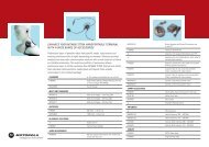
GENERAL RECEIVER TRANSMITTER<br />
ETSI ETS 300 394-1 Receiver Type: Class A and B Modulation Type: DQPSK<br />
Type Number:<br />
R1: 380-400 MHz: PT811F<br />
R2: 410-430 MHz: PT511F<br />
Frequency Range: R1: 380-400 MHz<br />
R2: 410-430 MHz<br />
Temperature Range for Transceiver: Channel Spacing: 25 kHz RF Power 1 Watt<br />
Operating: -20°C to +60°C Sensitivity (4%) BER: -112 dBm<br />
Storage: -40°C to +85°C Intermodulation:<br />
Interfering Signal Level:<br />
(4%) BER<br />
-47 dBm<br />
Frequency Range:<br />
R1: 380-400 MHz<br />
R2: 410-430 MHz<br />
Battery Types:<br />
Standard SNN5705B 800mAH (LiIon)<br />
Standard SNN5705C 800mAH (Lilon)<br />
High Capacity SNN5706A 1100mAH (LiIon)<br />
Selectivity Blocking:<br />
(50-100 kHz)<br />
Interfering Signal Level:<br />
(4%) BER<br />
-40 dBm<br />
Frequency Stability:<br />
Locked to Base<br />
Not Locked to Base<br />
± 100 Hz<br />
± 2 ppm<br />
Battery Voltage:<br />
Minimum:<br />
Nominal:<br />
3.4 Vdc<br />
3.8 Vdc<br />
<strong>Portable</strong> Dimensions HxWxD in MMs:<br />
140x55x31 mm<br />
Weight:<br />
<strong>MTH500</strong> <strong>Portable</strong> <strong>Radio</strong> <strong>Basic</strong> <strong>Service</strong> <strong>Manual</strong>- OVERVIEW<br />
CHAPTER 1<br />
OVERVIEW<br />
To achieve a high spectrum efficiency, the <strong>MTH500</strong> uses digital modulation technology<br />
and sophisticated voice-compression algorithm. The voice of the person<br />
speaking into the microphone is converted into a digital bit stream consisting of<br />
zeros (0) and ones (1). This stream is then modulated into a radio-frequency (RF)<br />
signal, which is transmitted over the air to another radio. The process is called digital<br />
modulation.<br />
Digital Modulation Technology<br />
The <strong>MTH500</strong> is a portable radio that has two models operating in two different<br />
frequency ranges: R1: 380-400 MHz and R2: 410-430 MHz. These radios can<br />
operate in dispatch and phone mode. Also, these radios can operate in TMO<br />
(Trunked Mode Operation) and DMO (Direct Mode Operation) modes. It uses<br />
two digital technologies: DQPSK and Time Division Multiple Access<br />
(TDMA).<br />
DQPSK is a modulation technique that transmits information by altering the<br />
phase of the radio frequency (RF) signal. Data is converted into complex symbols,<br />
which alter the RF signal and transmit the information. When the signal is<br />
received, the change in phase is converted back into symbols and then into the<br />
original data.<br />
The system can accommodate 4-voice channels in the standard 25 kHz channel as<br />
used in the two-way radio.<br />
Time Division Multiple Access (TDMA) is used to allocate portions of the RF<br />
signal by dividing time into four slots, one for each unit.<br />
Time allocation enables each unit to transmit its voice information without interference<br />
from other transmitting units. Transmission from a unit or base station is<br />
accommodated in time-slot lengths of 15 milliseconds and frame lengths of 60<br />
milliseconds. The TDMA technique requires sophisticated algorithms and a digital<br />
signal processor (DSP) to perform voice compressions/decompressions and<br />
RF modulation/demodulation.<br />
1
OVERVIEW: Voice Compression Technology<br />
Voice Compression Technology<br />
Voice is converted into a digital bit stream by sampling the voice at a high rate<br />
and converting the samples into numbers, which are represented by bits.<br />
Voice compression reduces the number of bits per second while maintaining the<br />
voice at an acceptable quality level. The <strong>MTH500</strong> uses a coding technique called<br />
ACELP (Algebraic Code Excited Linear Prediction). The compressed voice-data<br />
bits modulate the RF signal.<br />
Description<br />
Transceiver Description<br />
All the radio circuitry is contained in the Digital/RF Board and the keypad board. The Digital/RF board is divided<br />
into the following sections: digital, frequency generating, transmitter, and receiver.<br />
Digital Section Description<br />
The digital section includes the Redcap 2 that consists of the Mcore risk machine and the Digital Signal Processor<br />
(DSP).<br />
The Mcore is the controller of the Digital/RF Board. It controls the operation of the transmitter, receiver, audio,<br />
and synthesizer integrated circuits located in the RF section. It communicates with the keypad and display.<br />
The Digital Signal Processor (DSP) performs modulation and de-modulation functions for the radio. It also performs<br />
Forward Error Correction and other correction algorithms for overcoming channel errors and ACELP<br />
speech coding. It carries out linear 16-bit analog to digital conversions, audio filtering, and level amplification for<br />
the microphone audio input and the received audio output.<br />
The power and audio section is based on the GCAP III and includes power supplies, 13-bit CODEC, audio routing,<br />
microphone and ear piece amplifiers. A audio power amplifier is used for the loud speaker.<br />
2
<strong>MTH500</strong> <strong>Portable</strong> <strong>Radio</strong> <strong>Basic</strong> <strong>Service</strong> <strong>Manual</strong>- OVERVIEW<br />
Transmitter Path Description<br />
The transmitter circuitry includes a linear class AB Power Amplifier (PA) for the linear modulation of the<br />
<strong>MTH500</strong>. It also includes a novel cartesian feedback loop to enhance its transmitter linearity and reduced splattering<br />
power into adjacent channels.<br />
The transmitter path consists of a novel cartesian feedback loop that contains the forward and loop feedback paths.<br />
The forward path includes the low noise ODCT (Offset Direct Conversion Transmitter), Balun, Attenuator, and<br />
Power Amplifier. The loop feedback path includes the directional coupler, attenuator, and LNODCT (Low Noise<br />
Offset Direct Conversion Transmitter) ASIC.<br />
The cartesian Feedback output power passes to the antenna through the Isolator, Antenna Switch, and Harmonic<br />
Filter.<br />
Receiver Path Description<br />
The receiver path includes the Antenna Switch, SAW, LNA, ceramic filter, mixer, Crystal Filter, and WPIC<br />
(World Phone IC). The first IF consists of the Crystal Filter and WPIC ASIC.<br />
Frequency Generating Section Description<br />
The frequency generating section provides description of the following main components: Fractional-N Synthesizer,<br />
REF. oscillator, Main VCO, WPIC ASIC Synthesizers, LNODCT ASIC Synthesizer, External Offset and<br />
second LO Synthesizer, DSP PLL, and Host PLL.<br />
3
OVERVIEW: Description<br />
THIS PAGE INTENTIONALLY LEFT BLANK<br />
4
<strong>MTH500</strong> <strong>Portable</strong> <strong>Radio</strong> <strong>Basic</strong> <strong>Service</strong> <strong>Manual</strong> - TEST SETUP & TESTING<br />
CHAPTER 2<br />
TEST SETUP & TESTING<br />
!<br />
WARNING<br />
Any level 3 repairs can deeply affect the performance of<br />
the <strong>MTH500</strong> radio and may cause a new tuning procedure.<br />
This tuning procedure can be applied by certain<br />
authorised Motorola depots where the appropriate<br />
TEST & TUNE EQUIPMENT is available.The appropriate<br />
TEST & TUNE EQUIPMENT is a special automated<br />
test equipment which is only available at some Motorola<br />
factories and Motorola repair centers.<br />
Before Testing<br />
Carry out the following instructions before testing:<br />
• Check that you have a fully charged battery (Not required when using Battery<br />
Eliminator WALN4097).<br />
• Connect an RF cable to the N-type RF Connector of the IFR<br />
• Connect the other side of the RF cable to the antenna adapter assembly<br />
(Motorola Part Number FLN9659). Connect the RF cable to the other side of<br />
the antenna assembly connector.<br />
5
TEST SETUP & TESTING: Typical Test Setup<br />
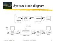
Typical Test Setup<br />
IFR 2968<br />
Antenna Adapter<br />
Assembly<br />
(FLN9659)<br />
<strong>MTH500</strong><br />
N-Type RF<br />
Connector<br />
RF Cable<br />
Battery<br />
Eliminator<br />
(WALN4097)<br />
3.8 V<br />
Power<br />
Supply<br />
Figure 1. Typical Test Setup<br />
6
<strong>MTH500</strong> <strong>Portable</strong> <strong>Radio</strong> <strong>Basic</strong> <strong>Service</strong> <strong>Manual</strong> - TEST SETUP & TESTING<br />
Test Check List:<br />
The following table summarises the required test setups.<br />
No.<br />
Test<br />
Name<br />
1. Base Station<br />
Registration<br />
Test Setup <strong>Radio</strong> Setup Test Conditions Limits<br />
Traffic<br />
Channel<br />
Control<br />
Channel<br />
390.125 MHz<br />
422.0125 MHz<br />
390.125 MHz<br />
422.0125 MHz<br />
3605<br />
880<br />
3605<br />
880<br />
<strong>TETRA</strong> 380+OMS for R1<br />
<strong>TETRA</strong> 410MS for R2<br />
<strong>TETRA</strong> 380+OMS for R1<br />
<strong>TETRA</strong> 410MS for R2<br />
Time Slot 3<br />
Country Code 753<br />
Network Code 2361<br />
Base Color 1<br />
Location Area 22<br />
Min Rx Level<br />
Max Tx Level<br />
Access Parameter<br />
Mobile Power<br />
Burst Type<br />
30dBm<br />
-53dBm<br />
Normal<br />
-110dBm<br />
30dBm<br />
2. Receiver<br />
RSSI<br />
RF Gen Level<br />
-80dBm<br />
3. Transmitter<br />
Burst Power<br />
RF Gen Level<br />
Burst Power<br />
Timing Error<br />
Vector Error<br />
Frequency Error<br />
-90dBm<br />
28-32dBm<br />
TEST SETUP & TESTING: Typical Test Setup<br />
No.<br />
Test<br />
Name<br />
Test Setup <strong>Radio</strong> Setup Test Conditions Limits<br />
1KHz Test<br />
Signal<br />
Group Mode<br />
-50dBm<br />
5. Call<br />
Processing<br />
Call to Mobile<br />
Private<br />
RF Gen Level<br />
Burst Power<br />
Timing Error<br />
Vector Error<br />
Frequency Error<br />
4 digit random<br />
number & “Send”<br />
-90dBm<br />
28-32dBm<br />
28-32dBm<br />
<strong>MTH500</strong> <strong>Portable</strong> <strong>Radio</strong> <strong>Basic</strong> <strong>Service</strong> <strong>Manual</strong> - TEST SETUP & TESTING<br />
Duplex Test<br />
1. Digital Duplex Test (Tx)<br />
Measurement Capabilities:<br />
Bar charts (Tx Power, Freq. Err, Vector Rms.), Spectrum Analyser, Power Analyser,<br />
Vector Analyser, Vector Diagrams<br />
How to Configure the IFR 2968 Setup<br />
Perform the following steps to configure the IFR 2968 with the radio set:<br />
1. Turn ON the IFR.<br />
2. Press “Systems” Mode Key (wait until the digital system is initialised).<br />
3. Press the “Tetra Mobile” soft key.<br />
4. Press the “Setup” soft key and enter the System Parameters Screen.<br />
5. Press the “Channel Plan” soft key.<br />
6. Press “Tetra 380+OMS” soft key for R1 or “Tetra 410MS” soft key for R2.<br />
The “Control Channel” automatically changes to “3600” for R1 or “800” for<br />
R2; and “Traffic Channel” automatically changes to “3700”for R1 or 900 for<br />
R2.<br />
7. Press twice the “Traffic Channel” soft key and check that the marker goes to<br />
Timeslot. Press Data key “3” followed by the “Traffic Channel” soft key, to<br />
change to Timeslot “3”.<br />
8. Press “Country Code” soft key. Enter “753” and “Country Code” soft key.<br />
9. Press “Network Code” soft key. Thereafter, enter “2361” and press “Network<br />
Code” soft key.<br />
10. Press “Base Color” soft key. Thereafter, enter “1” and press “Base Color” soft<br />
key.<br />
11. Press “More” soft key.<br />
12. Press “Location Area” soft key. Thereafter, enter “22” and press “Location<br />
Area” soft key.<br />
9
TEST SETUP & TESTING: Typical Test Setup<br />
13. Press “Min Rx Level” soft key. Thereafter, enter “-110dBm” and press “Min<br />
Rx Level” soft key.<br />
14. Press “Max Tx Level” soft key. Thereafter, enter “30dBm” and press “Max<br />
Tx Level” soft key.<br />
15. Press “Access Parameter” soft key. Thereafter, enter “-53dBm” and press<br />
“Access Parameter” soft key.<br />
16. Press “Test Mode” soft key. Press “Enable” soft key.<br />
17. Press “Base <strong>Service</strong>” soft key and “Supported” soft key.<br />
Note: You are entering base services setup.<br />
The displayed values are factory defaults and should not be changed.<br />
Power On Registration: required<br />
Power Off Deregistration: required<br />
Priority Cell: yes<br />
Minimum Mode <strong>Service</strong>: may be used<br />
Migration: supported<br />
System Wide <strong>Service</strong>s: normal mode<br />
18. Press “More” soft key.<br />
<strong>TETRA</strong> Voice <strong>Service</strong>s: supported<br />
Circuit Mode Data <strong>Service</strong>: supported<br />
(Reserved): available<br />
SNDCD <strong>Service</strong>: available<br />
Air Interface Encryption: not available<br />
Advanced Link: not supported<br />
19. Press the “Return” soft key.<br />
20. Press the “Neighbr Cell” soft key.<br />
21. Verify that the following NEIGHBOUR CELL INFO values are displayed:<br />
10
<strong>MTH500</strong> <strong>Portable</strong> <strong>Radio</strong> <strong>Basic</strong> <strong>Service</strong> <strong>Manual</strong> - TEST SETUP & TESTING<br />
Note: The displayed values are factory defaults and should not be changed.<br />
NEIGHBOUR CELL BROADCAST: NOT REQUIRED<br />
BROADCAST INTERVAL: 10s<br />
NEIGHBOUR CELL CHANNEL: 0000<br />
NEIGHBOUR CELL LOCATION AREA: 00000<br />
NEIGHBOUR CELL IDENTIFIER: 01<br />
SLOW RE-SELECT THRESHOLD: 10dB<br />
PRESS “MORE” SOFT KEY<br />
SLOW RE-SELECT HYSTERESIS: 10dB<br />
FAST RE-SELECT THRESHOLD: 10dB<br />
FAST RE-SELECT HYSTERESIS: 10dB<br />
22. Press the “Return” soft key.<br />
23. Press the “Trunk Type” soft key and “Tx Trunked” soft key.<br />
24. Press “More” Softkey.<br />
Note:<br />
The displayed values are factory defaults and should not be changed.<br />
It is not required to configure “Call Types” and “Messages”.<br />
25. Press “More” Softkey.<br />
How to Configure the IFR 2968 <strong>Manual</strong> Test Screen<br />
1. To enter “<strong>Manual</strong> test” screen, press “<strong>Manual</strong>” soft key.<br />
2. Press “Control Channel” soft key. Thereafter, enter “3605” for R1 and “880”<br />
for R2 and press “Control Channel” soft key (IFR 3605 = Rx 390.125MHz)<br />
for R1 and (IFR 880 = Rx 422.0125MHz) for R2.<br />
11
TEST SETUP & TESTING: RF Tests<br />
3. Press “Traffic Channel” soft key. Enter “3700” for R1 and “900” for R2 and<br />
press “Traffic Channel” soft key. The marker goes to Timeslot. Enter “3” and<br />
press “Traffic Channel” soft key. (Note that the Traffic Channel number<br />
changes automatically after entering the Control Channel number).<br />
4. Press “RF Gen Level” soft key. Thereafter, enter “-50” and press “dBm” data<br />
keys followed by “RF Gen Level” soft key.<br />
5. Press “Mobile Power” soft key, enter 30 dBm/1W, using soft key.<br />
6. Press “Burst Type” soft key and “Normal” soft key.<br />
7. This completes the test equipment configuration setup.<br />
Note: The System Setup Configuration Data is saved even after the power is<br />
turned off. However, the <strong>Manual</strong> Test Setup is not saved.<br />
RF Tests<br />
Receiver Tests<br />
Simulate Base Station (registration)<br />
1. Turn the radio ON<br />
2. Check that registration and “ITSI: ---/----/00000xxx” is displayed on the IFR<br />
“<strong>Manual</strong> Test” screen.<br />
Status: Registered (ITSI Attach)<br />
RSSI Test<br />
Before carrying out the following steps, record the Insertion loss (dB) of the cable<br />
loss value - (X) dB. Also, 0.5 dB, the maximum insertion loss of the Antenna<br />
assembly adapter should be added to the total calculated insertion loss.<br />
1. In the IFR <strong>Manual</strong> Test Mode, press the “RF Gen Level” Soft Key and enter<br />
(–) 80dbm.<br />
12
<strong>MTH500</strong> <strong>Portable</strong> <strong>Radio</strong> <strong>Basic</strong> <strong>Service</strong> <strong>Manual</strong> - TEST SETUP & TESTING<br />
2. Before testing, the radio should be configured to RSSI mode using the following<br />
Sequence, When performing steps 3 thru 6, make sure that you press the<br />
handset keys sequentially (less then a second between every consecutive<br />
press).<br />
3. Press the “Volume down” Key.<br />
4. Press the “1 “key, and “Menu” Key.<br />
5. Press the “2 “key, and “Menu” Key.<br />
6. Press the “3 “key.<br />
Hereafter, there is no need for quick sequence of pressing the handset keys.<br />
7. Press Key to enter the “4 Cells Info” state.<br />
8. Press “OK” using the Right (.) Key and press .<br />
9. Press “Trace” using the Right (.) Key.<br />
Note: RSSI results will flash on the screen every few seconds.<br />
The display shows: SERV: xx<br />
RSSI: -81<br />
SQE: xx<br />
Disregard the “SERV” and “SQE” results.<br />
The actual measured result should be:<br />
{-80dBm (IFR RF Gen Level) -0.5dB(adapter)-XdB (cable)} +/-1 dB.<br />
RSSI = {<strong>Radio</strong> RSSI Result – [Antenna assembly Adapter (dB) + Insertion loss<br />
of the Cable (dB)]}.<br />
To stop the “Trace” process, perform the following. When performing steps 10.<br />
thru 13., make sure that you press the handset keys sequentially (less then a second<br />
between every consecutive press):<br />
10. Press the “Volume down” Key.<br />
11. Press the “1” key, and “Menu” Key.<br />
12. Press the “2” key, and “Menu” Key.<br />
13. Press the “3” key.<br />
14. Press “Stop” using the Right (.) Key.<br />
13
TEST SETUP & TESTING: Call Processing Test<br />
15. Press “Back” twice using the Left (.) Key.<br />
Transmitter Tests<br />
1. Change the “Mode Key” of the radio to “Group Mode”.<br />
2. Press the “RF Gen Level” soft key. Enter “-90dBm” by pressing the data keys<br />
and “RF Gen Level” Key.<br />
3. Press the “PTT” of the radio and monitor the IFR “<strong>Manual</strong> Test” screen which<br />
displays the Burst Power, Power Profile, Timing Error, Vector Error, and Frequency<br />
Error.<br />
Note: You have to hold the PTT in the pressed position long enough to enable you<br />
to read the results.<br />
- Burst Power Required Results: 28-32dbm.<br />
- Power Profile: Passed.<br />
- Timing Error: < 0.25 symbols.<br />
- Vector Error: Max 10% RMS, Max 30% Peak.<br />
- Max 5% residual.<br />
- Frequency Error: -/+ 100Hz.<br />
4. Press the “Clear Down” soft key, to proceed with other tests.<br />
Call Processing Test<br />
Talk Back<br />
Before you start this test, make sure that handset and test equipment are configured<br />
the same as given in the Transmitter Test.<br />
1. Press the “PTT” and speak into the mic of the radio. You will hear the last<br />
three seconds of the speech frames before the “PTT” is released.<br />
14
<strong>MTH500</strong> <strong>Portable</strong> <strong>Radio</strong> <strong>Basic</strong> <strong>Service</strong> <strong>Manual</strong> - TEST SETUP & TESTING<br />
2. Press the “Test Sound” soft key to provide the 1kHz signal to the radio<br />
speaker.<br />
3. Press the “Silence” soft key to mute the 1KHz Audio Signal of the speaker.<br />
4. Press the “Clear Down” soft key and check that the “Cleardown Complete”<br />
status appear on the IFR “<strong>Manual</strong> Test” screen.<br />
Call to Mobile<br />
1. Press the radio “Mode” key and change to “Private” mode.<br />
2. Press the “Call Mobile” soft key on the IFR.<br />
Note: Select type of call.<br />
3. Press “Private” Call.<br />
Note: You will hear beeps from the handset speaker.<br />
4. Press “Abort Call” soft key.Duplex Test (Phone/Privet Mode)<br />
Digital Duplex Test (Tx)<br />
1. Press the “Mode” key of the radio and select “Phone” or “Privet” mode.<br />
2. Dial a random number “9359” using the Alphanumeric keys of the radio and<br />
press the “Send” Key.<br />
The following results are displayed on the IFR “<strong>Manual</strong> Test” Screen.<br />
- Burst Power Required Results: 28-32dbm<br />
- Power Profile: Passed<br />
- Timing Error:
3. Speak into the Handset Microphone and hear your speech (after a short delay)<br />
from the handset Earpiece.<br />
Note: If you need more details, press the “Duplex Test” mode key.<br />
4. Press the “duplex test (Tx)” soft key twice. The “Digital Duplex test” results<br />
will be displayed on the IFR screen providing you with the following bar<br />
charts measurement capabilities:<br />
- Power<br />
- Vector RMS<br />
- Frequency Error<br />
For Power Analyser Graph:<br />
5. Press “power ana” soft key.<br />
6. Check that the power frame falls within the limits.<br />
For Spectrum Analyser Graph:<br />
7. Press “Spect ana” soft key.<br />
8. Monitor the Tx frequency.<br />
For Vector Analyser Diagram:<br />
9. Press the “Vect Anal” soft key<br />
10. Monitor the constellation diagram.<br />
11. Press the “Vector Diagram” soft key.<br />
12. Press the “Rotated vector” to zoom in on the constellation.<br />
13. Press the handset “End” key.<br />
16
<strong>MTH500</strong> <strong>Portable</strong> <strong>Radio</strong> <strong>Basic</strong> <strong>Service</strong> <strong>Manual</strong> - TEST SETUP & TESTING<br />
DMO Test<br />
IFR 2968 Test Setup<br />
1. Press the “System” softkey.<br />
2. Press “<strong>TETRA</strong> Direct” Softkey.<br />
3. Press “Setup” Softkey.<br />
4. Press “Channel Plan” Softkey, press “<strong>TETRA</strong> 380+ODM” softkey for R1or<br />
<strong>TETRA</strong> 410+ODM for R2.<br />
5. Press DM Tx Mode” softkey, press “discontinue” softkey<br />
How to Configure the IFR 2968 <strong>Manual</strong> Test Screen<br />
1. Press the “<strong>Manual</strong>” softkey.<br />
2. Press “Channel” Softkey, thereafter enter “4000= 390 MHz” for R1or<br />
“1200=420 MHz for R2 and press “Channel” softkey.<br />
3. Press “Expected Power” Softkey, enter 30.0dBm/1.0 w.<br />
4. Press “Burst Type” Softkey and “Normal” softkey.<br />
<strong>Radio</strong> Configuration for DMO<br />
Modify the radio for DMO option by carrying out the following sequence:<br />
1. Turn ON the radio.<br />
2. Press the “Menu” key<br />
3. Press key and select mode “network”, press “OK” softkey.<br />
4. Select “OPERMODE”, and press “OK” softkey.<br />
5. Select “DIRECMODE” softkey and press “OK” softkey<br />
.<br />
17
TEST SETUP & TESTING: DMO Test<br />
RF Test - Transmit Test<br />
Hold the PTT in the pressed position long enough to enable you to read the<br />
results:<br />
• Results: - Power Profile: Passed<br />
• Burst Power Request Results: 28-32 dBm<br />
• Frequency Error: +/- 100Hz max.<br />
• Vector Error: Max. 10% RMS, Max. 30% Peak, Max. 5% Residual.<br />
18
<strong>MTH500</strong> <strong>Portable</strong> <strong>Radio</strong> <strong>Basic</strong> <strong>Service</strong> <strong>Manual</strong> - PROGRAMMING THE RADIO<br />
CHAPTER 3<br />
PROGRAMMING THE RADIO<br />
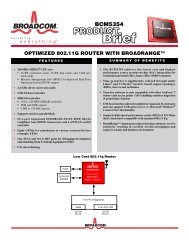
Before Using the Customer Programming Software<br />
(CPS)<br />
Before you begin programming, ensure the following:<br />
• That your radio battery is fully charged.<br />
• That you have connected the Data cable (FKN4897), according to Figure 2.<br />
• That the Customer Programming Software (CPS) is installed in your computer.<br />
p<br />
Serial Port<br />
(COM1/2)<br />
<strong>MTH500</strong><br />
<strong>Radio</strong><br />
To <strong>MTH500</strong><br />
Accessory Connector<br />
Data Cable<br />
(FKN4897)<br />
Figure 2. Setup for <strong>Radio</strong> Programming.<br />
19
PROGRAMMING THE RADIO: Programming the <strong>Radio</strong><br />
Programming the <strong>Radio</strong><br />
1. Verify that the radio is turned off.<br />
2. Run the Customer Programming Software (CPS) on your computer.<br />
3. Press the “1” and “9” keys together and then the On/Off key for about 3 seconds.<br />
Verify that no display appears on the LCD screen.<br />
4. Click the Toolbar “Read Phone” icon. Refer to the CPS Application Window<br />
Screen in the CPS User Guide, Publication No. 68P02956C20. The setup<br />
enters an initialization process that takes about 20 seconds. After that, a reading<br />
process starts.<br />
Note: While reading is in progress, the radio screen displays the following data:<br />
Diag. SW Ver. 01.01<br />
HW ID Code: XXX<br />
Flash: TE28F320C3BA<br />
Command READ REQ.<br />
--Done--<br />
00:00:00<br />
Appears at the<br />
end of the process<br />
Elapsed Time<br />
Indication<br />
A progress bar appear on the computer screen. After the reading process is<br />
finished, the radio Codeplug screen appears.<br />
CodePlug Programming<br />
1. On the menu bar, click “File” “Open”.<br />
2. Browse for the required Codeplug file and open the file.<br />
3. The Codeplug window appears on the screen.<br />
4. Click the Toolbar “Tools” and select “Write Entire Codeplug”.<br />
20
<strong>MTH500</strong> <strong>Portable</strong> <strong>Radio</strong> <strong>Basic</strong> <strong>Service</strong> <strong>Manual</strong> - PROGRAMMING THE RADIO<br />
5. Press “Yes” icon.<br />
Note: The Codeplug is now being written into the radio. A progress bar is displayed<br />
on the computer screen showing the writing status.<br />
After a successful writing, the message “The Operation Was Successful”<br />
appears on the computer screen.<br />
6. Press the OK button.<br />
Application Programming<br />
1. On the menu bar click “Tools”, “Write Software”.<br />
2. Press “Continue” icon.<br />
Note: The Codeplug reads data from the radio. A progress bar is displayed on the<br />
computer screen showing the writing status.<br />
After a successful reading, the “Write Software to Phone” appears on the<br />
computer screen.<br />
3. Choose the Customized Choice” option.<br />
4. Browse for the required application file and select it.<br />
5. Press the “Write” button.<br />
Note:The Codeplug is now being written into the radio. A progress bar is displayed<br />
on the computer screen showing the writing status.<br />
After a successful writing, the message “The Operation Was Successful” appears<br />
on the computer screen.<br />
6. Press the “Cancel” button.<br />
7. Click the Toolbar “R” (Reset) icon.<br />
21
PROGRAMMING THE RADIO: <strong>Manual</strong> Mode Testing<br />
<strong>Manual</strong> Mode Testing<br />
Preparation for Testing<br />
1. Verify that the radio is turned off.<br />
2. Press the “4”, “5” and “6” keys together and then, press the On/Off key to turn<br />
the radio on.<br />
3. The display shows “LCD Test Press Any Key To Proceed”.<br />
TESTS<br />
Note: Any key that will be pressed will cause the test to advance from one step to<br />
the next.<br />
LCD Display Test<br />
1. Press any key consecutively. The display shows horizontal lines that becomes<br />
thicker with every key press, until it becomes fully dark.<br />
2. Press any key again, the following appears at the top of the display:<br />
3. Press any key consecutively. The display shows vertical lines that becomes<br />
thicker with every key press, until it becomes fully dark.<br />
4. Press any key again. The display shows a map of Europe.<br />
5. Press any key again. The display shows “Vibrator On”, verify that the radio is<br />
vibrating.<br />
6. Press any key again. The display shows “Red Led on” and the Red LED at the<br />
top of the radio is lit.<br />
7. Press any key again. The display shows “Green Led on” and the Green LED<br />
at the top of the radio is lit.<br />
22
<strong>MTH500</strong> <strong>Portable</strong> <strong>Radio</strong> <strong>Basic</strong> <strong>Service</strong> <strong>Manual</strong> - PROGRAMMING THE RADIO<br />
8. Press any key, the LED located on the top of the radio (near the antenna),<br />
turns ON, and the two halves of this LED starts blinking with RED and Green<br />
lights.<br />
9. Press any key again. The display shows “Backlight On” and the display backlight<br />
is On.<br />
10. Press any key again. The display shows “Speaker Tone Test”, a tone is heard<br />
via the speaker.<br />
11. Press any key again. The display shows “Earpiece Tone Test”, a tone is heard<br />
via the earpiece.<br />
12. Press any key again. The display shows “Audio Loopback Test”, speak into<br />
the microphone, you should hear your voice via the earpiece.<br />
13. Press any key again. The display shows “Chopper-Noise Test”, a low hum is<br />
heard via the earpiece.<br />
14. Press any key again. The display shows all the radio keys.<br />
15. Press every key, one by one. Each key you press causes its respective display<br />
to disappear.<br />
16. Press Key. Every time you press causes the respective display to<br />
disappear.<br />
17. After pressing all keys, the display is clear.<br />
18. Turn the radio Off.<br />
Charger Recognition Test<br />
• Turn the radio ON.<br />
• Connect the Rapid Travel Charger accessory connector to the handset. Check<br />
whether the LCD display shows “charger connected” and that the keypad backlight<br />
is turned ON.<br />
• Connect the Vehicle Power Adapter (VPA) Charger accessory connector to the<br />
handset. Check whether the LCD display shows “charger connected” and that<br />
the keypad back-light is turned ON.<br />
• Connect the handset to the Desktop Charger. Check whether the LCD display<br />
shows “charger connected” and that the keypad back-light is turned ON.<br />
• Place the handset in the Digital Car Kit cradle. Verify that the car ignition<br />
switch is turned ON. Check whether the LCD display shows “Car it connected”,<br />
and that the keypad back-light is turned ON.<br />
23
PROGRAMMING THE RADIO: TESTS<br />
• Verify that the battery charger is in progress (the process advance is indicated<br />
on the Battery Strength icon).<br />
Press the “ON/OFF” key. The radio should turn OFF.<br />
24
<strong>MTH500</strong> <strong>Portable</strong> <strong>Radio</strong> <strong>Basic</strong> <strong>Service</strong> <strong>Manual</strong> - PROGRAMMING THE RADIO<br />
<strong>Service</strong> Flowchart<br />
Connect the radio to<br />
the IFR (1)<br />
1<br />
Maintenance<br />
level?<br />
Fail<br />
Perform all<br />
tests: RF and audio<br />
Pass<br />
Fail<br />
1<br />
Replace<br />
Main board<br />
(*) and re-test<br />
Fail<br />
- Replace the customer’s radio<br />
- Send the radio to Level 3 maintenance<br />
- Send the new TEI number to service provider<br />
- Clone/reprogram customer details to new unit<br />
Pass<br />
Replace<br />
other kits one-by-one<br />
and re-test<br />
- Replace battery<br />
- Replace antenna<br />
Pass<br />
- Send new TEI number to the<br />
service provider<br />
- Clone/reprogram, customer<br />
details to new unit<br />
(1) Refer to Replacement Kit table<br />
in Appendix.<br />
(*) Main Board: See <strong>Radio</strong> Replacement Parts List (Appendix A)<br />
Note: Not field replaceable for Latin America<br />
25
PROGRAMMING THE RADIO: <strong>Service</strong> Flowchart<br />
This page left blank intentionally<br />
26
<strong>MTH500</strong> <strong>Portable</strong> <strong>Radio</strong> <strong>Basic</strong> <strong>Service</strong> <strong>Manual</strong> - MAINTENANCE<br />
CHAPTER 4<br />
MAINTENANCE<br />
Preventive Maintenance<br />
This portable radio does not require a scheduled preventive maintenance program. However,<br />
periodic visual inspection is recommended.<br />
Inspection<br />
Inspect the radio’s external surfaces. A detailed inspection of interior circuitry is not<br />
needed or recommended.<br />
Cleaning<br />
The following procedures describe the recommended cleaning agents and methods to be<br />
used when cleaning the external and internal surfaces of the radio. External surfaces<br />
should be cleaned whenever a periodic visual inspection reveals the presence of smudges,<br />
compound, or grime. Internal surfaces (circuit boards and components) should be cleaned<br />
only when the radio is disassembled for servicing or repair.<br />
The only recommended agent for cleaning external radio surfaces is a 0.5% solution (one<br />
teaspoon of detergent per gallon of water) of mild dishwashing detergent in water. The<br />
internal surfaces should be cleaned only with isopropyl alcohol (70% by volume).<br />
27
MAINTENANCE: Safe Handling of CMOS Devices<br />
Safe Handling of CMOS Devices<br />
Complementary metal-oxide semiconductor (CMOS) devices are used in the radio. While<br />
the attributes of CMOS devices are many, their characteristics make them susceptible to<br />
damage by electrostatic or high voltage charges. Damage can be latent, resulting in failure<br />
occurring weeks or months later. Therefore, special precautions must be taken to prevent<br />
device damage during disassembly, troubleshooting, and repair. The following handling<br />
precautions are mandatory for CMOS circuits, and are especially important in low humidity<br />
conditions.<br />
• All CMOS devices must be stored or transported in conductive material so that all<br />
exposed leads are shorted together. CMOS devices must not be inserted into conventional<br />
plastic “snow” or plastic trays of the type that are used for storage or transportation<br />
of other semiconductor devices.<br />
• All CMOS devices must be placed on a grounded bench surface and the technician<br />
must also be grounded before handling the devices. This is done most effectively by<br />
having the technician wear a conductive wrist strap in series with a 100k resistor to<br />
ground.<br />
• Do not wear nylon clothing while handling CMOS circuits.<br />
• Do not insert or remove CMOS devices with power applied. Check all power supplies<br />
to be used for testing CMOS devices and be certain there are no voltage transients<br />
present.<br />
• When straightening CMOS device leads, provide ground straps for the apparatus used.<br />
• When soldering, use a grounded soldering iron.<br />
• All power must be turned off in a system before printed circuit boards containing<br />
CMOS devices are inserted, removed, or soldered.<br />
Level 1 and Level 2 Maintenance<br />
This manual covers Level 1 and Level 2 Maintenance: at Level 1 maintenance you replace<br />
the radio and/or accessories and send the faulty unified chassis and/or accessories to a<br />
higher level of maintenance; at level 2 maintenance a faulty kit is replaced.<br />
Note: For Level 1 maintenance instructions refer to the information given in Chapter 2.<br />
For Level 2 maintenance also refer to Chapter 2, and the instructions given below.<br />
28
<strong>MTH500</strong> <strong>Portable</strong> <strong>Radio</strong> <strong>Basic</strong> <strong>Service</strong> <strong>Manual</strong> - MAINTENANCE<br />
Removing and Installing the Antenna<br />
The antenna must be removed each time the back housing is removed.<br />
Recommended tools: no tools are required.<br />
To remove the antenna from the unit:<br />
(See Figure 1)<br />
1. Unscrew the antenna counter clockwise until it is detached from the handset.<br />
To install the antenna in the unit<br />
1. Screw the antenna clockwise to the handset.<br />
Figure 1 Antenna Removal and Installation<br />
29
MAINTENANCE: Removing and Installing Battery Door and Battery<br />
Removing and Installing Battery Door and Battery<br />
Recommended tools: no tools are required<br />
To remove the battery door from the unit:<br />
(See Figure 2)<br />
1. Place the unit facing down on the work area.<br />
2. Press the battery door release button, slide the door towards the bottom of the unit<br />
and lift it up from the unit.<br />
To remove the battery:<br />
(See Figure 3)<br />
1. Press the battery fastening bridge toward the upper side of the unit.<br />
2. Simultaneously, using other hand, release the battery from its chamber.<br />
To install the battery:<br />
1. Locate the battery so that the lower part (coloured silver) is touching the lower wall<br />
of the battery chamber.<br />
2. Carefully press the battery down until it snaps into location.<br />
To install the battery door:<br />
1. Position the door on the unit over the battery so that the door release button is just<br />
above the battery fastening bridge.<br />
2. Slide the door upward until the door snaps into location.<br />
3. Verify that the door is aligned with the handset back housing.<br />
30
<strong>MTH500</strong> <strong>Portable</strong> <strong>Radio</strong> <strong>Basic</strong> <strong>Service</strong> <strong>Manual</strong> - MAINTENANCE<br />
Figure 2 Battery Door Removal and Installation<br />
Figure 3 Battery Removal and Installation<br />
31
MAINTENANCE: Removing and Installing the Back Housing<br />
Removing and Installing the Back Housing<br />
Recommended tools: T-8 Torx bit, Torx driver, mini flat-tip screwdriver<br />
To remove the back housing from the unit:<br />
(See Figure 4)<br />
1. Remove the antenna, refer to “Removing and Installing the Antenna” on page 29.<br />
2. Remove the battery door and the battery, refer to “Removing and Installing Battery<br />
Door and Battery” on page 30.<br />
3. Place the unit facing down on the work area.<br />
4. Using the screwdriver remove the oval label at the top of the unit and the tamper evident<br />
label in the center to enable access to all six screws fastening the back housing.<br />
Clean the adhesive remains of the tamper evident label using alcohol.<br />
5. Using the Torx driver with the T-8 Torx bit, unscrew the six screws fastening the<br />
back housing.<br />
6. Carefully remove the back housing from the unit.<br />
To install the back housing:<br />
1. Position the back housing over the unit.<br />
2. Verify that the cover is positioned correctly, screw holes are aligned to the threads of<br />
the front housing, external antenna connector is inserted into its dedicated hole, and<br />
the styling groove of the back housing meets the styling groove of the front housing.<br />
3. Set the Torx driver to 3.5 in-lb.<br />
4. Screw the back housing screws in the following order: Upper left and right screws,<br />
center left and right screws and lower left and right screws.<br />
5. Glue a new oval label over the holes of the two upper screws and a new tamper evident<br />
label on the holes of the two center screws.<br />
6. Install the battery and the battery door, refer to “Removing and Installing Battery<br />
Door and Battery” on page 30.<br />
32
<strong>MTH500</strong> <strong>Portable</strong> <strong>Radio</strong> <strong>Basic</strong> <strong>Service</strong> <strong>Manual</strong> - MAINTENANCE<br />
Oval Label<br />
External Antenna Connector<br />
Back Housing<br />
Fastening Screws<br />
(X6)<br />
Figure 4 Back Housing Removal and Installation<br />
Removing and Installing the Main Board<br />
Recommended tools: no tools are required<br />
To remove the main board from the unit:<br />
(See Figure 5)<br />
1. Remove the back housing, refer to “Removing and Installing the Back Housing” on<br />
page 32.<br />
2. Gently lift the main board, I/O connector side at the bottom of the board first, and<br />
remove it from the unit.<br />
33
MAINTENANCE: Removing and Installing the Main Board<br />
To install the main board:<br />
1. Position the main board in location. Verify that the two guide pins are inserted into<br />
the holes in the main board.<br />
2. Gently push the main board down and verify that the Board-to-Board connector is<br />
properly connected to the keypad board.<br />
3. Verify that the I/O rubber seal is properly located in the unit.<br />
4. Install the back housing, refer to “Removing and Installing the Back Housing” on<br />
page 32.<br />
Main Board<br />
PHF Cover<br />
I/O Connector<br />
Rubber Seal<br />
Figure 5 Main Board Removal and Installation<br />
34
<strong>MTH500</strong> <strong>Portable</strong> <strong>Radio</strong> <strong>Basic</strong> <strong>Service</strong> <strong>Manual</strong> - MAINTENANCE<br />
Removing and Installing the Keypad and LCD Boards<br />
Recommended tools: mini flat-tip screwdriver<br />
To remove the keypad and LCD boards from the unit:<br />
(See Figure 6)<br />
1. Remove the back housing, refer to “Removing and Installing the Back Housing” on<br />
page 32.<br />
2. Place the unit facing down on the work area.<br />
3. Open the Personal Hands-Free Kit (PHF) jack cover (See Figure 5).<br />
4. Using the screwdriver, remove the chassis assembly including the main board, keypad<br />
board and LCD board, out from the unit.<br />
5. Place the chassis assembly, with the keypad and LCD boards facing down, on the<br />
work area.<br />
6. Remove the main board from the chassis assembly.<br />
7. Insert the screwdriver into one of the slots in the upper side of the chassis assembly,<br />
above the LCD board, and gently push the boards out from the chassis assembly.<br />
8. According to the board to be replaced, open the required Zero Insertion Force (ZIF)<br />
connector, release the flat cable and the board.<br />
To install the keypad and LCD boards:<br />
1. Place the keypad and LCD boards on the work area so that the ZIF connectors are facing<br />
up.<br />
CAUTION: Care must be taken when installing the keypad and LCD boards on the<br />
chassis. Failure to comply may result in tear of the flat cable between<br />
the two boards.<br />
2. Insert the flat cable into the ZIF connectors and close the connectors doors until a<br />
click is heard.<br />
3. Insert the LCD board between the two snags at the sides of the chassis assembly.<br />
4. Push the LCD board down until it snaps into location.<br />
5. Verify that the chassis center guide pin is properly located inside the hole in the LCD<br />
board and that the snag at the top of the chassis is inserted into the slot of the board.<br />
35
MAINTENANCE: Removing and Installing the Keypad and LCD Boards<br />
6. Install the keypad board on the chassis assembly.<br />
7. Verify that the keypad board is sited parallel to the chassis assembly.<br />
8. Verify that the main board is fully installed with the rubber seal.<br />
9. Turn the chassis assembly up side down.<br />
10. Install the main board on the chassis assembly. Verify that the two guide pins are<br />
inserted to the holes in the main board.<br />
11. Verify that the guide pins are properly located and that the Board-to-Board connector<br />
is properly connected to the main board.<br />
12. Install the chassis assembly with the boards into the unit. Verify that the I/O connector<br />
rubber seal is properly located in the unit.<br />
13. Install the back housing, refer to “Removing and Installing the Back Housing” on<br />
page 32.<br />
LCD Board<br />
Release Slot<br />
LCD Board<br />
Chassis Assembly<br />
Flat Cable<br />
Board-to-Board<br />
Connector<br />
ZIF Connectors<br />
Keypad Board<br />
Figure 6 Keypad and LCD Boards Removal and Installation<br />
36
<strong>MTH500</strong> <strong>Portable</strong> <strong>Radio</strong> <strong>Basic</strong> <strong>Service</strong> <strong>Manual</strong> - MAINTENANCE<br />
Removing and Installing the LCD Module Assembly<br />
Recommended tools: no tools are required<br />
To remove the LCD module assembly:<br />
(See Figure 7)<br />
1. Remove the LCD board, refer to “Removing and Installing the Keypad and LCD<br />
Boards” on page 35.<br />
Note: Do not touch the LCD module assembly in the active viewing area; fingerprints on<br />
this surface cannot be easily removed.<br />
2. Using your hand, gently disengage the right two snaps and rotate the LCD module<br />
assembly to the left until it disengaged from the LCD board.<br />
To install the LCD module assembly:<br />
Note: Do not touch the LCD module assembly in the active viewing area; fingerprints on<br />
this surface cannot be easily removed.<br />
1. Locate the LCD module above the LCD board so that the two guide pins are aligned<br />
with the holes in the LCD board.<br />
2. Gently push the module down, right snaps first and then left snaps.<br />
3. Verify that the snaps are located correctly inside the board slots.<br />
4. Remove the protective film from the LCD glass. Verify that no damage exists on the<br />
LCD glass.<br />
5. Install the LCD board, refer to “Removing and Installing the Keypad and LCD<br />
Boards” on page 35.<br />
37
MAINTENANCE: Removing and Installing the Keypad<br />
LCD Board<br />
LCD Module<br />
LCD Module<br />
Snaps<br />
(X4)<br />
Figure 7 LCD Module Removal and Installation<br />
Removing and Installing the Keypad<br />
Recommended tools: no tools are required<br />
To remove the keypad:<br />
(See Figure 8)<br />
1. Remove the chassis assembly, refer to “To remove the keypad and LCD boards from<br />
the unit:” on page 35, steps 1 through 3.<br />
2. Remove the keypad from the unit.<br />
To install the keypad:<br />
1. Install the keypad inside the front housing.<br />
2. Verify that all the keys are properly inserted into their dedicated holes.<br />
38
<strong>MTH500</strong> <strong>Portable</strong> <strong>Radio</strong> <strong>Basic</strong> <strong>Service</strong> <strong>Manual</strong> - MAINTENANCE<br />
3. Install the chassis assembly, refer to “To install the keypad and LCD boards:” on<br />
page 35, steps 1 and 2.<br />
Front Housing<br />
Chassis Assembly<br />
Including Main Board<br />
And<br />
LCD and Keypad<br />
Boards<br />
Keypad<br />
Figure 8 Keypad Removal and Installation<br />
Removing and Installing the Microphone<br />
Recommended tools: no tools are required<br />
To remove the microphone from the unit:<br />
(See Figure 9)<br />
1. Remove the chassis assembly, refer to “To remove the keypad and LCD boards from<br />
the unit:” on page 35, steps 1 through 3.<br />
2. Remove the microphone.<br />
39
MAINTENANCE: Removing and Installing the Earphone<br />
To install the microphone:<br />
1. Insert a microphone into location.<br />
2. Install the chassis assembly, refer to “To install the keypad and LCD boards:” on<br />
page 35, steps 1 and 2.<br />
Removing and Installing the Earphone<br />
Recommended tools: mini flat-tip screwdriver<br />
To remove the earphone from the unit:<br />
(See Figure 9)<br />
1. Remove the chassis assembly, refer to “To remove the keypad and LCD boards from<br />
the unit:” on page 35, steps 1 through 3.<br />
2. Using the screwdriver, remove the earphone from the unit. If the earphone was<br />
detached from its bottom plate, remove the plate as well.<br />
To install the earphone:<br />
1. Using the screwdriver, remove the protective film from the adhesive layer at the earphone<br />
bottom plate. Remove the Acoustic Safety Rubber.<br />
2. Insert the earphone into location. Verify that the two snags at the earphone sides are<br />
properly located in their dedicated slots.<br />
3. Gently push the earphone until it is firmly glued inside the front housing. Place the<br />
Acoustic Safety Rubber.<br />
4. Install the chassis assembly, refer to “To install the keypad and LCD boards:” on<br />
page 35, steps 1 and 2.<br />
40
<strong>MTH500</strong> <strong>Portable</strong> <strong>Radio</strong> <strong>Basic</strong> <strong>Service</strong> <strong>Manual</strong> - MAINTENANCE<br />
Earphone<br />
Acoustic Safety Rubber<br />
Front Housing<br />
Microphone<br />
Figure 9 Microphone and Earphone Removal and Installation<br />
41
MAINTENANCE: <strong>MTH500</strong> Unit - Exploded View<br />
<strong>MTH500</strong> Unit - Exploded View<br />
<strong>MTH500</strong> components are listed in the table below. The first column marked with a # sign provides you with the<br />
call out numbers of the components as marked in Figure 10 and Figure 11.<br />
<strong>MTH500</strong> Components List<br />
# Description Part/Kit<br />
1 Front Housing Assembly (Black)<br />
Front Housing Assembly (Blue)<br />
0186163T07<br />
0186163T08<br />
2 Keypad Assembly 0186630T01<br />
3 Chassis Assembly See Figure 10<br />
4 Back Housing Assembly (Black)<br />
Back Housing Assembly (Blue)<br />
5 Antenna 380-400 MHz (R1)<br />
Antenna 410-430 MHz (R2)<br />
0186396T04<br />
0186396T05<br />
8586381J03<br />
8586381J02<br />
6 Screw, Self Forming 0304637P17<br />
7 Label, Back 5486278T01<br />
8 Standard Battery Door Assembly (Black)<br />
Standard Battery Door Assembly (Blue)<br />
Extended Battery Door Assembly (Black)<br />
Extended Battery Door Assembly (Blue)<br />
0186613T01<br />
0186613T02<br />
0186239T01<br />
0186239T02<br />
9 LCD Module 7287702M01<br />
10 Keypad Kit FCN9090A<br />
11 Flex LCD to Keypad 8486498T01<br />
12 LCD Kit FCN9797A<br />
13 Chassis 2786168T01<br />
14 Main Board (R1)<br />
Main Board (R2)<br />
See <strong>Service</strong><br />
Replacement Kit<br />
Matrix in<br />
Appendix A<br />
42
<strong>MTH500</strong> <strong>Portable</strong> <strong>Radio</strong> <strong>Basic</strong> <strong>Service</strong> <strong>Manual</strong> - MAINTENANCE<br />
7<br />
5<br />
3<br />
1<br />
2<br />
8<br />
6(X6)<br />
4<br />
Figure 10 Exploded View<br />
43
MAINTENANCE: <strong>MTH500</strong> Unit - Exploded View<br />
12<br />
13<br />
9<br />
14<br />
10<br />
11<br />
Figure 11 Exploded View of Chassis Assembly<br />
44
Replacement Parts<br />
APPENDIX A<br />
REPLACEMENT PARTS AND KITS<br />
Damaged parts should be replaced with identical replacement parts.<br />
Replacement Parts<br />
For complete information on ordering required parts and kits, contact your local<br />
customer service representative.<br />
Level 3 Maintenance<br />
EMEA Region<br />
EMEA <strong>Radio</strong> Support Depots are level 3 service partners. The depots are capable of performing<br />
repairs down to component level where retuning is required. Contact your local<br />
CGISS office for information.<br />
Motorola European <strong>Radio</strong> Support Centre ERSC Phone: +49 6128 702618<br />
Heinrich Hertz Strasse 1<br />
D-65232 Taunusstein<br />
Germany<br />
ERSC Customer Information Desk available through the following service number:<br />
Austria: 06 60 75 41 Italy: 16 78 77 387<br />
Belgium: 08 00 72 471 Luxemburg: 08 00 23 27<br />
Denmark: 80 01 55 72 Netherlands: 60 22 45 13<br />
Finland: 08 00 11 49 10 Norway: 80 01 11 15<br />
France: 05 90 30 90 Portugal 05 05 49 35<br />
Germany: 01 30 18 75 24 Spain: 90 09 84 902<br />
Greece: 00 80 04 91 29 020 Sweden: 02 07 94 307<br />
UK: 08 00 96 90 95 Switzerland: 1 55 30 82<br />
Ireland 18 00 55 50 21 Iceland: 80 08 147<br />
or dial +49 6128 70 2618<br />
Please use these numbers for repair enquires only.<br />
45
Level 3 Maintenance<br />
Latin America Region<br />
Latin America <strong>Radio</strong> Support Centers<br />
The Customer Support is available through the following service centers:<br />
Warranty and Repairs:<br />
Motorola De Colombia <strong>Service</strong> Center<br />
Carrera 7 No. 71-52<br />
Torre B piso 13<br />
Oficina 1301<br />
Bogota- Colombia<br />
(571) 376-6990<br />
Motorola De Mexico <strong>Service</strong> Center<br />
Bosques de Alisos #125<br />
Col. Bosques de las Lomas<br />
CP 05120 Mexico DF<br />
5252576700<br />
Piece Parts:<br />
To order parts in Latin America and the Carribean:<br />
7:00 A.M. to 7:00 P.M. (Central Standard Time)<br />
Monday through Friday (Chicago, USA)<br />
1-847-538-8023<br />
Technical Support:<br />
https://businessonline.motorola.com, go to Contact Us to request technical support<br />
Motorola Parts (Accessories and Aftermarket Division AAD):<br />
Attention: Order Processing<br />
1313 E. Algonquin Road<br />
Schaumburg. IL. 60196<br />
Parts Identification:<br />
1-847-538-0021 (Voice)<br />
1-847-538-8194 (Fax)<br />
Some replacement parts, spare parts, and/or product information can be ordered directly.<br />
If a complete Motorola part number is assigned to the part, it is available from Motorola<br />
<strong>Radio</strong> After market and Accessory Division (AAD). If no part number is assigned, the part<br />
is not normally available from Motorola. If the part number is appended with an asterisk,<br />
the part is serviceable by Motorola Depot only. If a parts list is not included, this generally<br />
means that no user-serviceable parts are available for that kit or assembly.<br />
46
<strong>Radio</strong> Replacement Parts List<br />
<strong>Radio</strong> Replacement Parts List<br />
Part/Kit Number<br />
0186163T07<br />
0186163T08<br />
0186630T01<br />
0186396T04<br />
0186396T05<br />
8586381J03<br />
8586381J02<br />
0186613T01<br />
0186613T02<br />
0186239T01<br />
0186239T02<br />
<strong>MTH500</strong> Model Description<br />
Front Housing Assembly (Black)<br />
Front Housing Assembly (Blue)<br />
Keypad Assembly<br />
Back Housing Assembly (Black)<br />
Back Housing Assembly (Blue)<br />
Antenna 380-400 MHz (R1)<br />
Antenna 410-430 MHz (R2)<br />
Standard Battery Door Assembly (Black)<br />
Standard Battery Door Assembly (Blue)<br />
Extended Battery Door Assembly (Black)<br />
Extended Battery Door Assembly (Blue)<br />
7287702M01<br />
FCN9090A<br />
FCN9797A<br />
(See <strong>Service</strong><br />
Replacement Kit<br />
Matrix below)<br />
LCD Module<br />
Keypad Kit<br />
LCD Kit<br />
Main Board (R1)<br />
Main Board (R2)<br />
47
Accessories Replacement Parts List<br />
Accessories Replacement Parts List<br />
Kit Number<br />
<strong>MTH500</strong> Model Description<br />
Batteries<br />
FTN6030A<br />
FTN6037A<br />
FTN6031A<br />
FTN6038A<br />
Extended battery, 1100mAh, LiIon, Black (with battery door)<br />
Extended battery, 1100mAh, LiIon, Blue (with battery door)<br />
Standard battery, 800mAh, LiIon, Black (with battery door)<br />
Standard battery, 800mAh, LiIon, Blue (with battery door)<br />
Chargers<br />
FLN9468A<br />
SPN4716B<br />
SYN7455A<br />
SYN7456A<br />
FLN9469A<br />
Dual Pocket Desktop Charger<br />
Travel charger<br />
Plug Adapter UK for travel Charger<br />
Plug Adapter EU for travel Charger<br />
Vehicular battery charger<br />
Vehicular Adapters<br />
FLN2850A<br />
FLN9569A<br />
Car Kit<br />
Stand alone car cradle<br />
Audio accessories<br />
WADN4184A<br />
FLN9470A<br />
FLN9568A<br />
Headset with Boom mic and in line PTT<br />
Headset with Boom mic (On Hold)<br />
PHF<br />
Carrying Accessories<br />
FLN9476A<br />
FHN6246A<br />
Soft leather carry case<br />
Belt clip<br />
Others<br />
FKN4897A<br />
Data cable<br />
48
Recommended Programming Equipment<br />
Recommended Programming Equipment<br />
Name<br />
<strong>MTH500</strong> CPS<br />
Data Cable<br />
Part Number<br />
PMVN4065B<br />
FKN4897A<br />
<strong>Service</strong> Replacement Kit Matrix (1)<br />
Sales Model<br />
Description<br />
<strong>MTH500</strong> Black<br />
380-400 MHz<br />
PT811F<br />
<strong>MTH500</strong> Blue<br />
380-400 MHz<br />
PT811F<br />
<strong>MTH500</strong> Black<br />
410-430 MHz<br />
PT511F<br />
<strong>MTH500</strong> Blue<br />
410-430 MHz<br />
PT511F<br />
<strong>Service</strong><br />
Tanapa<br />
FUF12 08AS<br />
FUF1210AS<br />
FUF1211AS<br />
FUF12 09AS<br />
FUF1212AS<br />
FUF1213AS<br />
FUF12 22AS<br />
FUF1222AS<br />
FUF1225AS<br />
FUF12 22AS<br />
FUF1226AS<br />
FUF1227AS<br />
Description<br />
MT H50 0 B la c k<br />
S/T R1 CLEAR<br />
<strong>MTH500</strong> Black<br />
S/T R1 TEA1<br />
<strong>MTH500</strong> Black<br />
S/T R1 TEA2<br />
MT H50 0 B lu e<br />
S/T R1 CLEAR<br />
<strong>MTH500</strong> Blue<br />
S/T R1 TEA1<br />
<strong>MTH500</strong> Blue<br />
S/T R1 TEA2<br />
MT H50 0 B la c k<br />
S/T R2 CLEAR<br />
<strong>MTH500</strong> Black<br />
S/T R2 TEA1<br />
<strong>MTH500</strong> Black<br />
S/T R2 TEA2<br />
MT H50 0 B lu e<br />
S/T R2 CLEAR<br />
<strong>MTH500</strong> Blue<br />
S/T R2 TEA1<br />
<strong>MTH500</strong> Blue<br />
S/T R2 TEA2<br />
Note: All models listed in the <strong>Service</strong> Tanapa Column<br />
are not field replaceable for Latin America<br />
49
<strong>Service</strong> Replacement Kit Matrix (1)<br />
This page left blank intentionally<br />
50