Instrukcja montażu - Interex Katowice
Instrukcja montażu - Interex Katowice
Instrukcja montażu - Interex Katowice

You also want an ePaper? Increase the reach of your titles
YUMPU automatically turns print PDFs into web optimized ePapers that Google loves.
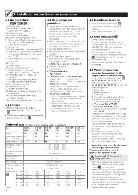
3. Installation instructions for the qualified installer<br />
3.1 Unit structure<br />
D H L M N<br />
15 Control panel<br />
16 Hot water outlet nozzle G ½<br />
17 Cold water inlet nozzle G ½<br />
18 Heating element<br />
19 Parasitic current anode<br />
20 Electronic module (control unit)<br />
21 Reset button of safety thermal cut-out<br />
22 Electronic module (regulation)<br />
23 Safety thermal cut-out<br />
24 Sealing ring<br />
25 Draining valve with hose connection G ¾<br />
26 Aperture for customer provided remote<br />
control of rapid heating in combination<br />
with PG 11<br />
27 Cable aperture PG 21 for electrical<br />
connection<br />
28 Inflow<br />
29 Outflow pipe<br />
30 Suspension bracket, top*<br />
31 Suspension bracket, bottom*<br />
(SHZ 120 LCD, SHZ 150 LCD only)<br />
32 Connection cable for „electronic<br />
modules“<br />
33 Sliding switch for operating modes<br />
34 Sliding switch for output variants<br />
35 Unit connection terminal<br />
36 Temperature sensor<br />
37 Parasitic current anode<br />
38 Customer provided remote control for<br />
rapid heating<br />
39 Customer provided power supply<br />
company contact<br />
* for customer provided screws 12 mm dia.<br />
3.2 Fittings<br />
Unvented (pressurized) mode of<br />
operation: Safety groups kV 30 or kV 40<br />
F .<br />
Vented (pressureless) mode of operation:<br />
Fittings without pressure G .<br />
Technical data (the data on the unit rating plate are applicable)<br />
3.3 Regulations and<br />
provisions<br />
The installation (water and electrical<br />
installation) and first start-up, as well as the<br />
maintenance of this unit may only be<br />
carried out by an approved specialist<br />
installer in accordance with these<br />
Instructions.<br />
Perfect function and operational safety are<br />
only guaranteed with original accessories<br />
and spare parts intended for the unit.<br />
IEE Regulations (electrical).<br />
Provisions of the local energy supply utility<br />
company.<br />
WRC Regulations (water).<br />
Provisions of the water supply utility<br />
company responsible.<br />
The following are also to be respected:<br />
The unit rating plate<br />
Technical data<br />
Water installation<br />
Pipe material:<br />
– Cold water pipe – Hot water pipe<br />
Copper pipe Copper pipe<br />
Steel pipe Steel or copper pipe<br />
Plastic pipe systems:<br />
Installation also in conjunction with<br />
DVGW-tested plastic pipe system for<br />
cold-water and hot-water pipe systems.<br />
• Electrical installation<br />
– Electrical connection only with fixed-laid<br />
leads in association with removable<br />
cable bushings.<br />
– The unit must be capable of all-pole<br />
disconnection from the mains, for<br />
example by fuses, with an isolating<br />
distance of at least 3 mm.<br />
Type SHZ 30 SHZ 50 SHZ 80 SHZ 100 SHZ 120 SHZ 150<br />
LCD LCD LCD LCD LCD LCD<br />
Capacity l 30 50 80 100 120 150<br />
Mixed water quantity l 59 97 159 198 235 292<br />
40 °C (15 °C / 65 °C)<br />
Weight empty kg 23.5 30 44 45 50 62.5<br />
Connectable to power 1 - 4 kW 1/N/PE ~ 230 V<br />
sources 1 - 4 kW 2/N/PE ~ 400 V<br />
1 - 6 kW 3/N/PE ~ 400 V<br />
Permissible operating<br />
pressure<br />
0.6 MPa (6 bar)<br />
Protection class<br />
EN 60529<br />
IP 25 D<br />
Test marking<br />
See unit rating plate<br />
Water connection<br />
G ½ (external thread)<br />
Flow rate<br />
max. 18 l/min<br />
Dimensions a mm 420 510 510 510 510 510<br />
D b mm 410 510 510 510 510 510<br />
h mm 750 720 1030 1030 1190 1425<br />
i mm – – – – 300 300<br />
k mm 700 600 900 900 900 1100<br />
l mm 70 140 150 150 310 345<br />
Table 1<br />
16<br />
3.5 Installation location<br />
• Install in a vertical position; see D .<br />
• In an area not subject to the risk of<br />
freezing.<br />
• Install close to the water tap.<br />
3.6 Unit installation E<br />
• Fit the suspension bracket.<br />
Select the securing material to suit the<br />
strength of the wall. With SHZ 120 LCD<br />
and SHZ 150 LCD, two suspension<br />
brackets are required.<br />
Any unevenness in the wall is to be<br />
compensated for by the spacer elements<br />
C provided (a. approx. 5 mm thick).<br />
• Suspend the unit.<br />
• Push the cover caps onto the suspension<br />
bracket (b).<br />
3.7 Water connection<br />
• Unvented (pressurized) for the<br />
supply of several draw-off points.<br />
– Install the type-tested safety groups F<br />
KV 30, Order No. 00 08 26, up to<br />
0.48 MPa water pipe pressure<br />
KV 40, Order No. 00 08 28, up to 1 MPa<br />
water pipe pressure<br />
a Safety valve<br />
b Backflow preventer<br />
c Test valve<br />
d Throughflow isolating valve (choke)<br />
e Pressure reducer (with KV 40)<br />
f Test nozzle for pressure gauge<br />
g Thermostat fitting TA 260<br />
Order No. 00 34 66 (order<br />
separately), also possible in conjunction<br />
with KV 40.<br />
– Establish dimensions for the outflow pipe<br />
for a fully-opened safety valve. The drain<br />
aperture of the safety valve must remain<br />
open to the atmosphere.<br />
– The drain for the safety group is to be<br />
installed with a constant downwards<br />
inclination.<br />
– The information provided in the<br />
Installation Instructions for the safety<br />
group are to be respected.<br />
– Set a maximum flow rate of 18 l/min at<br />
the choke of the safety group.<br />
• Vented (pressureless) for the supply<br />
of one single draw-off point<br />
The units are suitable for vented<br />
(pressureless) operation mode.<br />
Do not block off the drain and<br />
fittings pivot arm.<br />
– With this installation the Stiebel Eltron<br />
fittings for vented wall-mounted water<br />
heaters G are to be used.<br />
– Before connecting the fitting the water<br />
pipe must be thoroughly flushed through.<br />
– Each time heating takes place, expansion<br />
water will drip out of the drain.<br />
– For use, installation, first start-up, and<br />
maintenance, the same instructions apply<br />
as for the operation of unvented<br />
(pressurized) water heaters.