Mixed Layout Katalog - FCT
Mixed Layout Katalog - FCT
Mixed Layout Katalog - FCT

Create successful ePaper yourself
Turn your PDF publications into a flip-book with our unique Google optimized e-Paper software.
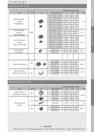
PCB Hole Pattern for Connectors with Right Angled PCB Terminations<br />
Leiterplattenlochbild für Steckverbinder mit abgewinkeltem Leiterplattenanschluss<br />
All PCB hole patterns apply to male connectors with right angled PCB terminations (signal contacts P5) with metal brackets F1080-13B. When using<br />
female connectors the hole pattern must be mirrored on the Y-axis.<br />
Measurements without tolerances are in accordance with DIN ISO 2768 m. For the required dimension F and drilling diameters see page 69 and 70.<br />
Alle Lochbilder gelten für Stiftsteckverbinder mit abgewinkeltem Leiterplattenanschluss (Signalkontakte P5) und Metallwinkel F1080-13B. Bei Verwendung<br />
von Buchsensteckverbindern muss das Lochbild an der Y-Achse gespiegelt werden.<br />
Maße ohne Toleranzangabe nach DIN ISO 2768 m. Erforderliches Maß F und Bohrungsdurchmesser siehe Seite 69 und 70.<br />
0.926<br />
23.52<br />
0.57<br />
14.48<br />
0.302<br />
7.67<br />
0.86 0.034<br />
0<br />
0.234<br />
5.94<br />
14.48 0.57<br />
23.52 0.926<br />
10.67 0.42<br />
2.54 0.1<br />
0.926<br />
23.52<br />
14.48 0.57<br />
7.77 0.306<br />
0<br />
0.218<br />
0.326<br />
0.57<br />
5.54<br />
8.28<br />
14.48<br />
A1 A2 A3 1 2 A4<br />
0.926<br />
23.52<br />
10.67 0.42<br />
A1 A2 A3 A4 A5<br />
F<br />
9.4 0.37<br />
3 5<br />
F<br />
3 0.118<br />
0,1<br />
1 0.039<br />
3 0.118<br />
0.1 0.1<br />
0<br />
4.14 0.163<br />
6.91 0.272<br />
9.68 0.381<br />
0.37 2.54 0.1<br />
9.4<br />
23.52 0.926<br />
14.48 0.57<br />
7.77 0.306<br />
2.77 0.109<br />
0<br />
2.77 0.109<br />
5.54 0.218<br />
8.28 0.326<br />
14.48 0.57<br />
A3 A2 5<br />
1 A1<br />
10 6<br />
F<br />
0.926<br />
23.52<br />
0.42<br />
10.67<br />
2.54 0.1<br />
9.4 0.37<br />
0.926<br />
23.52<br />
13.82 0.544<br />
8.28 0.326<br />
5.54 0.218<br />
2.77 0.109<br />
0<br />
2.77 0.109<br />
5.54 0.218<br />
8.28 0.326<br />
13.82 0.544<br />
A1 1<br />
7 A2<br />
8 15<br />
F<br />
0.926<br />
23.52<br />
10.67 0.42<br />
1<br />
0.039<br />
3 0.118<br />
0.1 0.1<br />
0<br />
1.4 0.055<br />
1.4 0.055<br />
4.14 0.163<br />
6.91 0.272<br />
9.68 0.381<br />
1 0.039<br />
0.1<br />
9.68 0.381<br />
6.91 0.272<br />
4.14 0.163<br />
1.4 0.055<br />
0<br />
1.4 0.055<br />
4.14 0.163<br />
6.91 0.272<br />
9.68 0.381<br />
3 0.118<br />
0.1<br />
DIMENSIONS IN MILLIMETERS - VALUES FOR INCHES IN BRACKETS - TECHNICAL DATA SUBJECT TO CHANGE ML 12/2008<br />
79