Mixed Layout Katalog - FCT
Mixed Layout Katalog - FCT Mixed Layout Katalog - FCT
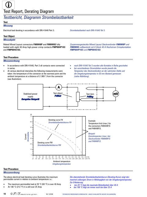
Test Report, Derating Diagram Testbericht, Diagramm Strombelastbarkeit Test Messung Electrical load derating in accordance with DIN 41640 Part 3. Strombelastbarkeit nach DIN 41640 Teil 3. Test Object Messobjekt Mated Mixed Layout connectors FM8W8P and FM8W8S fully loaded with eight 40 Amp high power crimp contacts FMP004P103 and FMP004S103. Zusammengesteckte Mixed Layout Steckverbinder FM8W8P und FM8W8S vollbestückt mit 8 Stück 40 A Hochstrom Crimpkontakten FMP004P103 und FMP004S103. Test Procedure Messanordnung · In accordance with DIN 41640, Part 3 all contacts were connected in series. · At various electrical intensities the following measurements were taken: the temperature of the connector at the warmest point and the ambient temperature at a distance of (1.969 ") from the connector (see illustration). · nach DIN 41640 Teil 3 wurden alle Kontakte in Reihe geschaltet. · bei verschiedenen Stromstärken wurde jeweils die Temperatur des Steckverbinders an der wärmsten Stelle und die Umgebungstemperatur in 50 mm Abstand gemessen (siehe Abbildung). Test Procedure Messanordnung The above electrical load derating curve illustrates the maximum permissible current in relation to ambient temperature i.e.: • The maximum permissible load at 20 °C (68 °F) is over 40 Amp • At 100 °C (212 °F) it is still over 25 Amp Die obenstehende Strombelastbarkeitskurve (Derating-Kurve) zeigt den maximal zulässigen Strom in Abhängigkeit von der Umgebungstemperatur. Zur Erläuterung: • bei 20 °C liegt die maximale Belastbarkeit über 40 A • bei 100 °C liegt sie immer noch bei über 25 A 10 ML 12/2008 TECHNISCHE ÄNDERUNGEN VORBEHALTEN - MAßE IN MILLIMETER (INCHES IN KLAMMERN)
Contact Arrangements (FM-Series with Mounted Signal Contacts) Polbilder (FM-Baureihe, mit fest eingebauten Signalkontakten) DIMENSIONS IN MILLIMETERS - VALUES FOR INCHES IN BRACKETS - TECHNICAL DATA SUBJECT TO CHANGE ML 12/2008 11
- Page 2 and 3: All Products are RoHS compliant. A
- Page 4 and 5: List of Contents Inhaltsverzeichnis
- Page 6 and 7: List of Contents Inhaltsverzeichnis
- Page 8 and 9: Technical Data, FM Connectors Techn
- Page 12 and 13: Contact Arrangements (FU/FL Series,
- Page 14 and 15: Mounting and Mating Instructions (A
- Page 16 and 17: Straight Signal Contacts Gerade Sig
- Page 18 and 19: Right Angled Signal Contacts Abgewi
- Page 20 and 21: Mixed Layout Connector with Plastic
- Page 22 and 23: Crimp Connectors Crimp Steckverbind
- Page 24 and 25: Turned Contacts for Crimp Connector
- Page 26 and 27: Code for Special Contacts Nummernsc
- Page 28 and 29: Coaxial Contacts Koaxialkontakte Te
- Page 30 and 31: Coaxial Contacts, Mating Area Dimen
- Page 32 and 33: FMX Coaxial Contacts, 50 Ohm, Right
- Page 34 and 35: FMS Coaxial Contacts, 50 Ohm, Strai
- Page 36 and 37: FMS Coaxial Contacts, 75 Ohm, Strai
- Page 38 and 39: Coaxial Contacts, Mating Area Dimen
- Page 40 and 41: Wiresplice Wiresplice 50 Ohm 50 Ohm
- Page 42 and 43: FME Coaxial Contacts, 50 Ohm, Right
- Page 44 and 45: FME Coaxial Contacts, 75 Ohm, Strai
- Page 46 and 47: FME Coaxial Contacts, 75 Ohm, Right
- Page 48 and 49: PCB Hole Pattern for Connectors wit
- Page 50 and 51: PCB Hole Pattern for Connectors wit
- Page 52 and 53: PCB Hole Pattern for Connectors wit
- Page 54 and 55: PCB Hole Pattern for Connectors wit
- Page 56 and 57: PCB Hole Pattern for Connectors wit
- Page 58 and 59: FBM Coaxial Contacts, Mating Area D
Test Report, Derating Diagram<br />
Testbericht, Diagramm Strombelastbarkeit<br />
Test<br />
Messung<br />
Electrical load derating in accordance with DIN 41640 Part 3.<br />
Strombelastbarkeit nach DIN 41640 Teil 3.<br />
Test Object<br />
Messobjekt<br />
Mated <strong>Mixed</strong> <strong>Layout</strong> connectors FM8W8P and FM8W8S fully<br />
loaded with eight 40 Amp high power crimp contacts FMP004P103<br />
and FMP004S103.<br />
Zusammengesteckte <strong>Mixed</strong> <strong>Layout</strong> Steckverbinder FM8W8P und<br />
FM8W8S vollbestückt mit 8 Stück 40 A Hochstrom Crimpkontakten<br />
FMP004P103 und FMP004S103.<br />
Test Procedure<br />
Messanordnung<br />
· In accordance with DIN 41640, Part 3 all contacts were connected<br />
in series.<br />
· At various electrical intensities the following measurements were<br />
taken: the temperature of the connector at the warmest point and the<br />
ambient temperature at a distance of (1.969 ") from the connector<br />
(see illustration).<br />
· nach DIN 41640 Teil 3 wurden alle Kontakte in Reihe geschaltet.<br />
· bei verschiedenen Stromstärken wurde jeweils die<br />
Temperatur des Steckverbinders an der wärmsten Stelle und<br />
die Umgebungstemperatur in 50 mm Abstand gemessen<br />
(siehe Abbildung).<br />
Test Procedure<br />
Messanordnung<br />
The above electrical load derating curve illustrates the maximum<br />
permissible current in relation to ambient temperature i.e.:<br />
• The maximum permissible load at 20 °C (68 °F) is over 40 Amp<br />
• At 100 °C (212 °F) it is still over 25 Amp<br />
Die obenstehende Strombelastbarkeitskurve (Derating-Kurve) zeigt den<br />
maximal zulässigen Strom in Abhängigkeit von der Umgebungstemperatur.<br />
Zur Erläuterung:<br />
• bei 20 °C liegt die maximale Belastbarkeit über 40 A<br />
• bei 100 °C liegt sie immer noch bei über 25 A<br />
10 ML 12/2008<br />
TECHNISCHE ÄNDERUNGEN VORBEHALTEN - MAßE IN MILLIMETER (INCHES IN KLAMMERN)


