

EI1410-E-03 CAL.cdr - OEM Automatic AB
EI1410-E-03 CAL.cdr - OEM Automatic AB
EI1410-E-03 CAL.cdr - OEM Automatic AB

Create successful ePaper yourself
Turn your PDF publications into a flip-book with our unique Google optimized e-Paper software.
Please read this document carefully before using this product. The guarantee will be invalidated if the device is<br />
damaged by not following instructions detailed in the manual. <strong>CAL</strong> Controls shall not be responsible for any<br />
damage or losses however caused, which may be experienced as a result of the installation or use of this product.<br />
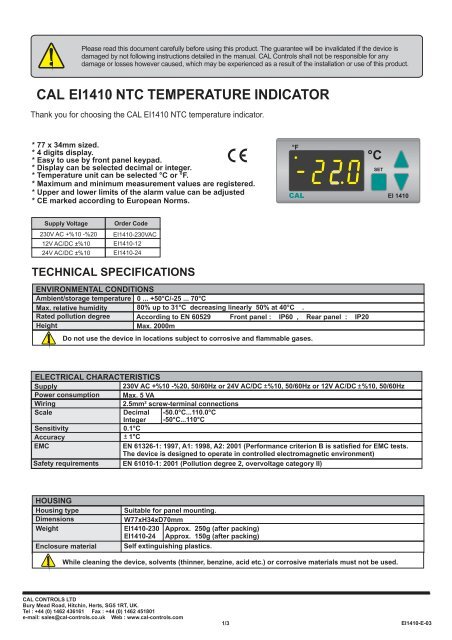
<strong>CAL</strong> <strong>EI1410</strong> NTC TEMPERATURE INDICATOR<br />
Thank you for choosing the <strong>CAL</strong> <strong>EI1410</strong> NTC temperature indicator.<br />
* 77 x 34mm sized.<br />
* 4 digits display.<br />
* Easy to use by front panel keypad.<br />
* Display can be selected decimal or integer.<br />
* Temperature unit can be selected °C or °F.<br />
* Maximum and minimum measurement values are registered.<br />
* Upper and lower limits of the alarm value can be adjusted<br />
* CE marked according to European Norms.<br />
°F<br />
<strong>CAL</strong><br />
°C<br />
SET<br />
EI 1410<br />
Supply Voltage<br />
Order Code<br />
230V AC +%10 -%20<br />
12V AC/DC ± %10<br />
<strong>EI1410</strong>-230VAC<br />
<strong>EI1410</strong>-12<br />
24V AC/DC ± %10 <strong>EI1410</strong>-24<br />
TECHNI<strong>CAL</strong> SPECIFICATIONS<br />
ENVIRONMENTAL CONDITIONS<br />
Ambient/storage temperature 0 ... +50°C/-25 ... 70°C<br />
Max. relative humidity 80% up to 31°C decreasing linearly 50% at 40°C .<br />
Rated pollution degree According to EN 60529 Front panel : IP60 , Rear panel : IP20<br />
Height<br />
Max. 2000m<br />
Do not use the device in locations subject to corrosive and flammable gases.<br />
ELECTRI<strong>CAL</strong> CHARACTERISTICS<br />
Supply<br />
Power consumption<br />
Wiring<br />
230V AC +%10 -%20, 50/60Hz or 24V AC/DC ± %10, 50/60Hz or 12V AC/DC ± %10, 50/60Hz<br />
Max. 5 VA<br />
2.5mm² screw-terminal connections<br />
Scale<br />
Decimal -50.0°C...110.0°C<br />
Integer -50°C...110°C<br />
Sensitivity<br />
Accuracy<br />
0.1°C<br />
± 1°C<br />
EMC<br />
EN 61326-1: 1997, A1: 1998, A2: 2001 (Performance criterion B is satisfied for EMC tests.<br />
The device is designed to operate in controlled electromagnetic environment)<br />
Safety requirements EN 61010-1: 2001 (Pollution degree 2, overvoltage category II)<br />
HOUSING<br />
Housing type<br />
Dimensions<br />
Weight<br />
Enclosure material<br />
Suitable for panel mounting.<br />
W77xH34xD70mm<br />
<strong>EI1410</strong>-230 Approx. 250g ( after packing)<br />
<strong>EI1410</strong>-24 Approx. 150g (after packing)<br />
Self extinguishing plastics.<br />
While cleaning the device, solvents (thinner, benzine, acid etc.) or corrosive materials must not be used.<br />
<strong>CAL</strong> CONTROLS LTD<br />
Bury Mead Road, Hitchin, Herts, SG5 1RT, UK.<br />
Tel : +44 (0) 1462 436161 Fax : +44 (0) 1462 451801<br />
e-mail: sales@cal-controls.co.uk Web : www.cal-controls.com<br />
1/3<br />
<strong>EI1410</strong>-E-<strong>03</strong>
www.cal-controls.com<br />
Input<br />
UP.l1<br />
UP.l1 - HYS<br />
LO.l1 + HYS<br />
LO.l1<br />
t<br />
Alarm<br />
t<br />
When alarm case happens, process value flashes.<br />
DIMENSIONS<br />
34mm<br />
°F<br />
<strong>CAL</strong><br />
85mm<br />
°C<br />
SET<br />
EI 1410<br />
1<br />
Flush mounting<br />
clamp<br />
Depth<br />
70mm<br />
2<br />
Panel<br />
8mm<br />
Rubber<br />
gasket<br />
For removing mounting clamps:<br />
- Push up the flush-mounting<br />
clamp in direction 1 as<br />
shown in the figure left.<br />
- Then, pull out the clamp in<br />
direction 2.<br />
R<br />
W<br />
1 2 3 4 5 6 7 8 9 10 11 12<br />
NTC<br />
SENSOR<br />
230V AC +10% -20%<br />
50/60Hz 5 VA<br />
Panel cut-out<br />
71mm<br />
Note :<br />
1) Panel thickness should be maximum 7mm.<br />
2) If there is no 60mm free space at back side of<br />
the device,it would be difficult to remove it from<br />
the panel.<br />
<strong>EI1410</strong>-230VAC<br />
NTC TEMPERATURE INDICATOR<br />
SN: XXXXXXXXX<br />
29mm<br />
Equipment is protected througout<br />
by DOUBLE INSULATION.<br />
Holding screw 0.4-0.5Nm<br />
NOTE :<br />
SUPPLY:<br />
184-253V AC<br />
50/60Hz 3VA<br />
7<br />
8<br />
Line<br />
Neutral<br />
Fuse<br />
F 100 mA<br />
250V AC<br />
Switch<br />
230V AC<br />
Supply<br />
1) Mains supply cords shall meet the requirements of<br />
IEC 60227 or IEC 60245.<br />
2) In accordance with the safety regulations, the power<br />
supply switch shall bring the identification of the relevant<br />
instrument and it should be easily accessible by the operator.<br />
Fuse should be connected.<br />
Cable size: 1,5mm²<br />
CONNECTION DIAGRAM<br />
<strong>CAL</strong> <strong>EI1410</strong> is intended for installation in control panels. Make sure that the device is used only for<br />
intended purpose. The shielding must be grounded on the instrument side. During an installation, all<br />
of the cables that are connected to the device must be free of electrýcal power. The device must be<br />
protected against inadmissible humidity, vibrations, severe soiling and make sure that the operation<br />
temperature is not exceeded. All input and output lines that are not connected to the supply network<br />
must be laid out as shielded and twisted cables. These cables should not be close to the power<br />
cables or components. The installation and electrical connections must be carried out by qualified<br />
staff and must be according to the relevant locally applicable regulations.<br />
www.cal-controls.com<br />
<strong>EI1410</strong>-230VAC<br />
NTC TEMPERATURE INDICATOR<br />
SN: XXXXXXXXX<br />
www.cal-controls.com<br />
<strong>EI1410</strong>-24<br />
NTC TEMPERATURE INDICATOR<br />
SN: XXXXXXXXX<br />
230V AC +10% -20%<br />
50/60Hz 5 VA<br />
NTC<br />
SENSOR<br />
24V AC/DC 10%<br />
50/60Hz 5VA<br />
NTC<br />
SENSOR<br />
W R<br />
1 2 3 4 5 6 7 8 9 10 11 12<br />
W R<br />
1 2 3 4 5 6 7 8 9 10 11 12<br />
2/3<br />
<strong>EI1410</strong>-E-<strong>03</strong>
<strong>EI1410</strong> PROGRAMMING DIAGRAM<br />
°F<br />
°C<br />
SET<br />
Increment<br />
key<br />
Decrement<br />
key<br />
Used for changing parameters and increasing the setpoint value. When held down for a<br />
few seconds, the change rate accelerates.<br />
Used for changing parameters and decreasing the setpoint value. When held down for a<br />
few seconds, the change rate accelerates.<br />
ENDA<br />
EI 1410<br />
Programming<br />
key<br />
SET<br />
Used for displaying value of the selected parameter and adjusting the selected<br />
parameter.<br />
RUN MODE<br />
SET<br />
While holding key, measured maximum temperature value appears.<br />
When the device is first enerjised or by pressing key, while holding key,<br />
SET<br />
Process value<br />
measured maximum temperature value is made equal to process temperature value.<br />
SET<br />
While holding key, measured minimum temperature value appears.<br />
When the device is first enerjised or by pressing key, while holding key,<br />
SET<br />
measured minimum temperature value is made equal to process temperature value.<br />
If both & keys are pressed and held for 3 seconds, programming mode is entered or run mode is returned.<br />
PROGRAMMING MODE<br />
SET<br />
If this key is pressed,<br />
upper limit value<br />
appears.<br />
SET<br />
If this key is pressed,<br />
lower limit value<br />
appears.<br />
SET<br />
Upper limit<br />
value<br />
Lower limit<br />
value<br />
Hysteresis<br />
value<br />
SET<br />
By using and keys, while holding key, the upper limit can be adjusted to desired value<br />
between -50.0°C and 110.0°C . Minimum value of this parameter must be ( lo.l1 + 2 * HYS ).<br />
SET<br />
By using and keys, while holding key, the lower limit can be adjusted to desired value<br />
between -50.0°C and 110.0°C. Maximum value of this parameter must be ( Up.l1 - 2 * HYS ).<br />
SET<br />
By using and keys, while holding key, hysteresis value can be adjusted to desired value<br />
If this key is pressed,<br />
hysteresis value<br />
appears.<br />
SET<br />
Offset<br />
value<br />
between 0.0°C and 10.0°C. Maximum value of this parameter must be ( Up.l1 - Lo.l1 ) / 2.<br />
SET<br />
By using and keys, while holding key, offset can be adjusted to desired value<br />
If this key is pressed,<br />
offset value<br />
appears.<br />
SET<br />
Display<br />
resolution<br />
If this key is pressed,<br />
display alternatives<br />
appears.<br />
Temperature<br />
SET<br />
unit<br />
between 0 .0°C ile 20.0°C.<br />
SET<br />
By using and keys, while holding key, display can be selected decimal or integer.<br />
When Yes is selected, decimal case is entered. If no is selected, integer case is entered.<br />
All of other parameters are adjusted according to selection.<br />
SET<br />
By using and keys, while holding key, temperature unit can be selected °C or °F.<br />
If this key is pressed,<br />
temperature unit<br />
appears.<br />
If no key is pressed within 20 seconds, the device will time out back to the run mode. Alternatively, re-energising the device, run mode is entered.<br />
ERROR MESSAGES<br />
Means, thermostat probe is short circuit or temperature value is higher than the scale.<br />
Means, thermostat probe is broken or temperature value is lower than the scale.<br />
3/3<br />
<strong>EI1410</strong>-E-<strong>03</strong>


