Installation Manual for SMX Modules - OEM Automatic AB
Installation Manual for SMX Modules - OEM Automatic AB Installation Manual for SMX Modules - OEM Automatic AB
Installation Manual 3 Device types 3.1 Module overview 3.1.1 SMX10 Type designation Device design Design of module with the following periphery: 14 digital inputs 2 Pulse outputs 2 Relay outputs 2 LOSIDE 2 HISIDE 2 Signal outputs 1 Diagnostic and configuration interface 1 Function button 1 7-segment display 1 Status-LED 14 Status-LEDs for inputs 2 Status-LEDs for pulse outputs 2 Status-LEDs for relay outputs 2 Status-LEDs for HISIDE 1 Backplane bus interface Characteristics of the module: • Logic processing up to Pl e acc. to EN ISO 13849-1 or SIL 3 acc. to EN 61508 • Open programmable small control system for up to 800 IL instructions • Logic diagram oriented programming • Pulse outputs for cross-shorting detection of digital input signals • Safety function of external contact monitoring for connected switchgear • Monitored relay outputs for safety relevant functions • Monitored HISIDE/LOSIDE outputs for safety relevant functions • CAN-communication in connection with the SMX5x for diagnose via backplane bus system Mounting on top hat rail HB-37350-810-01-10E-EN SMX installation manual.doc Page 8 of 8
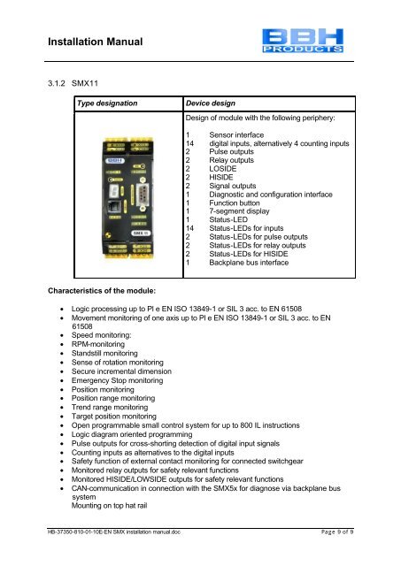
Installation Manual 3.1.2 SMX11 Type designation Device design Design of module with the following periphery: 1 Sensor interface 14 digital inputs, alternatively 4 counting inputs 2 Pulse outputs 2 Relay outputs 2 LOSIDE 2 HISIDE 2 Signal outputs 1 Diagnostic and configuration interface 1 Function button 1 7-segment display 1 Status-LED 14 Status-LEDs for inputs 2 Status-LEDs for pulse outputs 2 Status-LEDs for relay outputs 2 Status-LEDs for HISIDE 1 Backplane bus interface Characteristics of the module: • Logic processing up to Pl e EN ISO 13849-1 or SIL 3 acc. to EN 61508 • Movement monitoring of one axis up to Pl e EN ISO 13849-1 or SIL 3 acc. to EN 61508 • Speed monitoring: • RPM-monitoring • Standstill monitoring • Sense of rotation monitoring • Secure incremental dimension • Emergency Stop monitoring • Position monitoring • Position range monitoring • Trend range monitoring • Target position monitoring • Open programmable small control system for up to 800 IL instructions • Logic diagram oriented programming • Pulse outputs for cross-shorting detection of digital input signals • Counting inputs as alternatives to the digital inputs • Safety function of external contact monitoring for connected switchgear • Monitored relay outputs for safety relevant functions • Monitored HISIDE/LOWSIDE outputs for safety relevant functions • CAN-communication in connection with the SMX5x for diagnose via backplane bus system Mounting on top hat rail HB-37350-810-01-10E-EN SMX installation manual.doc Page 9 of 9
- Page 1 and 2: Installation Manual Installation Ma
- Page 3 and 4: Installation Manual 9 SAFETY RELEVA
- Page 5 and 6: Installation Manual 1.2 Co-valid do
- Page 7: Installation Manual 2 Safety regula
- Page 11 and 12: Installation Manual 3.1.4 SMX12A Ty
- Page 13 and 14: Installation Manual 3.1.6 Type plat
- Page 15 and 16: Installation Manual 4.2 Installatio
- Page 17 and 18: Installation Manual 4.4 External 24
- Page 19 and 20: Installation Manual 4.6 Connection
- Page 21 and 22: Installation Manual Note: • In th
- Page 23 and 24: Installation Manual 2. Single-chann
- Page 25 and 26: Installation Manual 4.8 Connection
- Page 27 and 28: Installation Manual Attention: The
- Page 29 and 30: Installation Manual 6.2 Connection
- Page 31 and 32: Installation Manual 6.4 Connection
- Page 33 and 34: Installation Manual 8 Sensor type A
- Page 35 and 36: Installation Manual For application
- Page 37 and 38: Installation Manual The test functi
- Page 39 and 40: Installation Manual 10.1.2 Single-p
- Page 41 and 42: Installation Manual 10.1.4 Single-p
- Page 43 and 44: Installation Manual 10.1.6 Wiring o
- Page 45 and 46: Installation Manual 10.2.2 Wiring t
- Page 47 and 48: Installation Manual Response times
- Page 49 and 50: Installation Manual 11 Start-up 11.
- Page 51 and 52: Installation Manual 11.4 Terminal a
- Page 53 and 54: Installation Manual 12 Safety relat
- Page 55 and 56: Installation Manual 14 Technical da
- Page 57 and 58: Installation Manual 15.2 Alarm list
<strong>Installation</strong> <strong>Manual</strong><br />
3.1.2 <strong>SMX</strong>11<br />
Type designation<br />
Device design<br />
Design of module with the following periphery:<br />
1 Sensor interface<br />
14 digital inputs, alternatively 4 counting inputs<br />
2 Pulse outputs<br />
2 Relay outputs<br />
2 LOSIDE<br />
2 HISIDE<br />
2 Signal outputs<br />
1 Diagnostic and configuration interface<br />
1 Function button<br />
1 7-segment display<br />
1 Status-LED<br />
14 Status-LEDs <strong>for</strong> inputs<br />
2 Status-LEDs <strong>for</strong> pulse outputs<br />
2 Status-LEDs <strong>for</strong> relay outputs<br />
2 Status-LEDs <strong>for</strong> HISIDE<br />
1 Backplane bus interface<br />
Characteristics of the module:<br />
• Logic processing up to Pl e EN ISO 13849-1 or SIL 3 acc. to EN 61508<br />
• Movement monitoring of one axis up to Pl e EN ISO 13849-1 or SIL 3 acc. to EN<br />
61508<br />
• Speed monitoring:<br />
• RPM-monitoring<br />
• Standstill monitoring<br />
• Sense of rotation monitoring<br />
• Secure incremental dimension<br />
• Emergency Stop monitoring<br />
• Position monitoring<br />
• Position range monitoring<br />
• Trend range monitoring<br />
• Target position monitoring<br />
• Open programmable small control system <strong>for</strong> up to 800 IL instructions<br />
• Logic diagram oriented programming<br />
• Pulse outputs <strong>for</strong> cross-shorting detection of digital input signals<br />
• Counting inputs as alternatives to the digital inputs<br />
• Safety function of external contact monitoring <strong>for</strong> connected switchgear<br />
• Monitored relay outputs <strong>for</strong> safety relevant functions<br />
• Monitored HISIDE/LOWSIDE outputs <strong>for</strong> safety relevant functions<br />
• CAN-communication in connection with the <strong>SMX</strong>5x <strong>for</strong> diagnose via backplane bus<br />
system<br />
Mounting on top hat rail<br />
HB-37350-810-01-10E-EN <strong>SMX</strong> installation manual.doc Page 9 of 9


