View Complete Issue PDF
View Complete Issue PDF
View Complete Issue PDF

You also want an ePaper? Increase the reach of your titles
YUMPU automatically turns print PDFs into web optimized ePapers that Google loves.
The Officers, Directors, and members of the Academy would like to acknowledge<br />
very gratefully the contribution of the firm listed below, whose generosity helped make<br />
possible the publication of this issue of Clinical Prosthetics and Orthotics.<br />
Kingsley Manufacturing Company,<br />
1984 Placentia Avenue, P.O. Box CSN 5010,<br />
Costa Mesa, CA 92628; 800-854-3479.<br />
Hosmer Dorrance Corporation,<br />
561 Division Street, P.O. Box 37,<br />
Campbell, CA 95008; 800-538-7748.<br />
Motion Control, Inc.,<br />
1005 South 300 West,<br />
Salt Lake City, UT 84101; 801-364-1958.<br />
Clinical Prosthetics and Orthotics (ISSN 0279-6910) is published quarterly by the American Academy of Orthotists and Prosthetists,<br />
717 Pendleton St., Alexandria, VA 22314. Subscriptions: $15.00 domestic, $20.00 foreign, $30.00air mail. POSTMASTER: Send<br />
address changes to Clinical Prosthetics and Orthotics, 717 Pendleton St., Alexandria, VA 22314.<br />
® 1985 by the American Academy of Orthotists and Prosthetists. Printed in the United States of America. All rights reserved.
Oinical<br />
^prosthetics<br />
^Orthotics<br />
Editor<br />
Charles H. Pritham, CPO<br />
Managing Editor<br />
Christopher R. Colligan<br />
Associate Editor<br />
Sharada Gilkey<br />
Editorial Board<br />
H. Richard Lehneis, PhD,<br />
CPO—Chairman<br />
Charles H. Pritham, CPO—Editor<br />
Charles H. Epps, MD<br />
Tamara Sowell, RPT<br />
Dennis Clarke, CPO<br />
Volume 9<br />
Contents<br />
Number 1<br />
Lead Articles<br />
Historical Aspects of Powered<br />
Limb Prostheses<br />
Dudley S. Childress, PhD<br />
An American history of the development<br />
of powered upper-limb prostheses from<br />
1915 to the present and beyond.<br />
Innovation and Improvements of<br />
Body-Powered Arm Prostheses:<br />
A First Step 13<br />
Maurice A. LeBlanc, MSME, CP<br />
LeBlanc is heading a study to improve<br />
body-powered arm prostheses. Here are<br />
the results of the first step of his study—a<br />
survey to verify needs and priorities of<br />
arm amputees.<br />
Editorial<br />
Externally Powered Prostheses<br />
for Children—1984 17<br />
Charles H. Epps, Jr., MD<br />
An overview of externally powered<br />
prostheses currently available for<br />
children in the U.S.<br />
Technical Article<br />
Upper Limb Prosthetic Management—<br />
Hybrid Design Approaches 23<br />
John N. Billock, CPO<br />
The hybrid arm prosthesis—a design<br />
approach that taylors the elements of two<br />
or more systems into one to meet the<br />
specific needs of upper-limb amputees.<br />
Technical Notes<br />
Conventional Fitting<br />
of an Unconventional Orthosis<br />
Donald L. Fornuff, CP<br />
Two-Stage Cast-taking Procedure<br />
for PTS Prosthesis 30<br />
Kurt Marschall, CPO<br />
Features<br />
Questionnaire Analysis 20<br />
Questionnaire 21<br />
Letters to the Editor 35<br />
Calendar 37<br />
26
Historical Aspects of Powered<br />
Limb Prostheses<br />
by Dudley S. Childress, Ph.D.<br />
INTRODUCTION<br />
People involved in work on powered limb<br />
prostheses may wonder if the history of this<br />
field is important. My answer is that one can<br />
learn a lot from history. Nevertheless, Hegel<br />
from the viewpoint of important meetings and<br />
events. Control approaches, another viewpoint,<br />
are considered but not emphasized. Also, the<br />
perspective is from America.<br />
has said, "What history teaches us is that men<br />
never learned anything from it." Unfortunately,<br />
it sometimes does seem true in prosthetics that<br />
we have not always profited from past experiences.<br />
Too many aspects of the work are never<br />
PROLOGUE (1915-1945)<br />
The first powered prosthesis, of which I am<br />
aware, was a pneumatic hand patented in Germany<br />
published, and the multidisciplinary nature of<br />
in 1915. 13<br />
A drawing of an early pneu<br />
the field produces papers in a broad spectrum of<br />
journals that are difficult to track. Books on the<br />
field are, unfortunately, not numerous.<br />
The brief history that follows is by no means<br />
complete, and since some of it involves years<br />
that are within readers' memories, I apologize<br />
in advance for omissions that anyone may consider<br />
significant. The history is intended to entice<br />
readers to look more deeply into historical<br />
issues. It is also intended to give some perspective<br />
on the field and to dispel notions that powered<br />
prostheses are only recent developments of<br />
"bionic man" research. Wilson 50<br />
has written a<br />
brief history on external power of limb prostheses<br />
matic hand is shown in Figure 1. Figure 2<br />
shows a drawing of what I believe to be the first<br />
electric powered hand. These drawings were<br />
published in 1919 in Ersatzglieder und Arbeitshilfen<br />
(Substitute Limbs and Work Aids). 35<br />
This German publication illustrates the importance<br />
of history in prosthetics, containing ideas<br />
that are still being discovered today. Although<br />
the book Treatise on Artificial Limbs by A.A.<br />
Marks, published in 1901, does not contain<br />
anything about powered limbs, it too illustrates<br />
the importance of history in the field because<br />
many ideas put forward in it are also quite modern.<br />
and the handbook by Spaeth 41<br />
contains an Powered limbs were probably not used to any<br />
introductory chapter on this subject. Brief surveys<br />
significant extent between the World Wars, but<br />
are included in papers (e.g. Childress 10<br />
or CO2 powered limbs were used by Weil as early<br />
Bottomley et al. 7 )<br />
as 1948. 28<br />
Development work continued at Heidelberg<br />
Powered limbs have existed for some seventy<br />
years. This roughly corresponds with the history<br />
of powered hand tools and other powered<br />
technical devices used so widely in modern<br />
society (e.g. airplanes, automobiles, etc.). This<br />
is not surprising since technology in most fields<br />
during the 1950's under Marquardt, 28<br />
and the Otto Bock Company became involved<br />
with the work about 1962. Laboratories at Munster<br />
and Hannover were also involved in this<br />
early work that led to clinical applications of<br />
gas powered prostheses. Part of Germany's<br />
tends to mirror the state of technology generally. prominent position in The the history prosthetics of powered field can limbs is also c<br />
parable in length with the history of an identifiable<br />
field known as "limb prosthetics."<br />
I have chosen to consider the history of powered<br />
prostheses from a hardware viewpoint and<br />
be traced to their early commitment to development<br />
work in the entire field of prosthetics.<br />
Kiessling 23<br />
was the major U.S. investigator<br />
involved with CO2 powered limbs. Of course,
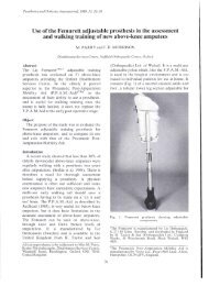
Figure 1. Early compressed-gas powered hand (Perhaps<br />
the first powered prosthesis component). From Ersatzglieder<br />
under Arbeitshilfen (Limb Substitutes and Work<br />
Aids) 1919.<br />
Figure 2. Early electric hand component (Perhaps the first<br />
electric hand mechanism). From Ersatzglieder und Arbeitshilfen<br />
(Limb Substitutes and Work Aids) 1919.<br />
the McKibben muscle 17<br />
was developed in the<br />
U.S., but has been used mainly in orthotics.<br />
The first, as far as we know, myoelectric<br />
prosthesis was developed during the early 40's<br />
by Reinhold Reiter, a physicist working with<br />
the Bavarian Red Cross. He published his work<br />
in 1948 33<br />
but it was not widely known and myoelectric<br />
control was destined to be "rediscovered"<br />
in England, in the Soviet Union, and<br />
perhaps other places during the 1950's. Economic<br />
conditions in Germany after World War<br />
II prevented the work on myoelectric control<br />
from being continued there. Figure 3 shows a<br />
picture of the first myoelectric hand prosthesis<br />
which was probably used around 1943. The<br />
system was controlled by a vacuum tube amplifier<br />
and was not portable. The hand was a modified<br />
Hüfner Hand that contined a control electro-magnet.<br />
The system was heavy, large, and<br />
not battery operated; the idea was to use it as a<br />
Figure 3. Electric powered hand used by Reiter in development of first myoelectric prosthesis (Circa 1943). It consists of a<br />
Hüfner Hand in which a control magnet has been built. From Grenzgebiete der Medizin (Frontiers of Medicine) 1948.
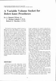
Figures 4a and 4b. Two views of the mechanics of the Vaduz Hand. Note position and force feedback links that connect to the<br />
inner transducer. This connects to an outer transducer (a bladder) adjacent to the residual limb in the socket. This<br />
voluntary-closing hand was activated by muscle bulge. It operated as a position servomechanism. It contained a gear shifting<br />
mechanism and a current cut-off mechanism. From Bulletin of Prosthetics Research, BPR 10-6, 1966.<br />
special prosthesis at a work station. Reiter<br />
hoped that further development could make it<br />
portable.<br />
It is an interesting coincidence that the results<br />
of the first experiments with myoelectric control<br />
were published in 1948, the same year in which<br />
the development of the transistor was announced.<br />
Practical myoelectrically controlled<br />
prostheses required the transistor and its subsequent<br />
refinements.<br />
Although Reiter conceived and developed the<br />
idea of myoelectric control in the early 1940's,<br />
others had the same idea later and apparently<br />
independently. The late Professor Norbert<br />
Weiner of Massachusetts Institute of Technology<br />
is reported to have suggested the concept<br />
around 1947. Berger & Huppert 4<br />
presented the<br />
idea in 1952. Battye, Nightingale, and Whillis 3<br />
at Guy's Hospital in London developed a myoelectric<br />
control system for a powered prosthesis<br />
in 1955 in what was for many years thought to<br />
be the first demonstration of this principle. That<br />
they were not first in no way detracts from their<br />
accomplishment. Soviet scientists were apparently<br />
the first to use transistors in a myoelectrically<br />
controlled prosthesis. The so-called<br />
Russian Hand 24<br />
was the first semi-practical<br />
myo-electrical limb to be used clinically and<br />
was sold (although not widely used) on a license<br />
basis for application in Great Britain and in Canada.<br />
THE EARLY YEARS<br />
(1945-1967)<br />
As far as the United States is concerned, the<br />
year 1945 was a turning point in prosthetics. In<br />
January 1945, military personnel, surgeons,<br />
prosthetists, and engineers met in Chicago<br />
(Thorne Hall, Northwestern University) to consider<br />
what should be done about limb prosthetics.<br />
This meeting is recognized as the beginning<br />
of the prosthetics research and development<br />
program by the U.S. government. This program<br />
ultimately resulted in the establishment of the<br />
Committee on Prosthetics Research and Development<br />
(CPRD) of the National Research<br />
Council which guided work in the field for over<br />
twenty-five years. The post-war years saw tre-
mendous advances in limb prosthetics in general,<br />
although powered prosthesis development<br />
was slow. During the period 1946-1952, Alderson,<br />
with the support of IBM and the Veterans<br />
Administration, developed several electricpowered<br />
limbs. 1<br />
These IBM arms were impressive<br />
engineering achievements for the time, but<br />
they were somewhat difficult for amputees to<br />
use.<br />
The Vaduz hand, developed during the early<br />
post-war period, appears to have been a prosthesis<br />
ahead of its time and one that contained<br />
antecedents of today's electric hands. A German<br />
team headed by Dr. Edmund Wilms settled<br />
in Vaduz, Lichtenstein after World War II to<br />
continue their prosthetic hand development<br />
work. They wanted to create a hand controlled<br />
by the muscles of prehension, which would operate<br />
on a portable power source. The hand<br />
they created is shown in Figure 4. It has been<br />
described by Wilms. 49<br />
This hand had a gear<br />
shifting mechanism to enable it to obtain high<br />
gripping force from an electric motor while also<br />
having reasonable finger velocity. This is a<br />
principle used in current Otto Bock hands. The<br />
hand used a unique controller in which a pneumatic<br />
bag inside the socket detected muscle<br />
bulge through pneumatic pressure, which in<br />
turn operated a switch-activated position servomechanism<br />
to close the voluntary-closing<br />
electric hand. This principle foreshadows the<br />
concept of extended physiological proprioception<br />
(EPP) introduced by Simpson 39 (Figure 5).<br />
The complete system is shown in Figure 6.<br />
Figure 5. Diagram of control circuit for Vaduz Hand.<br />
Muscle bulge compresses the outer transducer, which<br />
causes expansion of the inner transducer, moving the spindle<br />
upward. This activates the switches that close the hand.<br />
A link with the output moves the switch assembly along so<br />
that the hand stops when the link movement corresponds<br />
with spindle movement. Force feedback opens the closing<br />
limit switch at some force level when the hand meets an<br />
object. This conserves battery power. From Bulletin of<br />
Prosthetics Research, BPR 10-6, 1966.<br />
Figure 6. <strong>View</strong> of complete Vaduz system. Note similarity of myoelectric systems. From Bulletin of Prosthetics<br />
BPR 10-6, 1966.<br />
Research,
Lucaccini, Kaiser & Lyman 26<br />
evaluated the<br />
Vaduz Hand. The center at the University of<br />
California at Los Angeles, under Lyman's direction,<br />
also evaluated the Alderson-IBM arm,<br />
the Heidelburg Pneumatic Prosthesis, and other<br />
externally powered systems, as well as conducting<br />
many control studies of their own.<br />
After 1953, the Vaduz Hand was marketed<br />
from Paris and consequently was sometimes<br />
called the French Hand. It apparently was difficult<br />
to keep in optimal mechanical adjustment,<br />
but it must be considered as one of the most<br />
important ancestors of today's electric hands,<br />
and a hand that contained many novel and intriguing<br />
concepts. It was available through the<br />
mid-sixties.<br />
The Russian Hand and Vaduz Hand were<br />
followed by an English Hand developed around<br />
1965 by Bottomley. 5 This was the first myoelectrically<br />
controlled hand that exhibited proportional<br />
control (Figure 7). This prosthesis<br />
also contained several novel features for that<br />
period of time, such as internal force and velocity<br />
feedback and a unique myoelectric signal<br />
smoothing principle called "autogenic backlash,"<br />
which produced a more or less consistent<br />
direct current (DC) output from the fluctuating<br />
myoelectric signal while not sacrificing time response.<br />
The Russian Hand (Figure 8), Vaduz Hand,<br />
and Bottomley Hand were single-function devices<br />
and non-adaptive. During the early 1960's<br />
Tomovic suggested an adaptive, multi-articu-<br />
Figure 7. <strong>View</strong> of myoelectric hand developed by Bottomley<br />
in England. Note the two external packages on the<br />
table, battery on left and electronics on right. This was the<br />
first myoelectrically controlled hand that had proportional<br />
control. From Science Journal article by R.N. Scott,<br />
March 1966.<br />
Figure 8. Photograph of Russian Hand. This was the first myoelectric hand that was transistorized and portable (Circa 1959).<br />
The external battery pack is shown in the center of the photograph. The electronic package is beneath the battery. The battery<br />
charger is at left. Note the long electrode wires and the prosthesis suspension straps. From Science Journal article by R.N.<br />
Scott, March 1966.
lated hand with rudimentary sensory qualities.<br />
This resulted in the Belgrade Hand. 32<br />
Although<br />
this hand was not used clinically to any great<br />
extent, it was used extensively in research laboratories<br />
and has had influence on robotic hand<br />
developments. In 1965, a Swedish research<br />
group began work on an electric hand which<br />
was adaptive and which had multiple functions<br />
(two types of grasp, wrist flexion-extension,<br />
and supination-pronation). This became known<br />
as the SVEN-Hand 19<br />
(Figure 9). It also has been<br />
used extensively in research, particularly regarding<br />
multi-function control 18<br />
and concepts<br />
employed in it are utilized today in Swedish<br />
developments.<br />
Congenital amputations caused by the drug<br />
Thalidomide resulted in expanded interest in<br />
powered prostheses in the 1960's. Pneumatic<br />
systems by Otto Bock (hand, hooks, wrist<br />
rotators, and elbows) were fitted successfully,<br />
particularly in Germany by Marquardt, 28<br />
to<br />
many children born without limbs. However,<br />
pneumatic systems never caught on well in the<br />
U.S. probably because of difficulties with the<br />
compressed gas. Cannisters of gas were expensive<br />
and difficult to maintain and distribute<br />
in the U.S. American laws also required steel<br />
cannisters, which added to weight. Pneumatic<br />
systems have low energy storage densities and<br />
this meant that multiple cannisters were required,<br />
particularly to supply the energy needs<br />
of adult prostheses. On the other hand, these<br />
systems have actuators that are light in weight,<br />
which are easily controlled, and which have<br />
natural compliance properties that keep them<br />
from being rigid.<br />
Electric power can be stored more cheaply,<br />
more safely, and with greater density than gas<br />
power. Also, the control possibilities made possible<br />
by electronic circuits have given electrical<br />
systems an advantage. Unfortunately, the actuators<br />
(electric motors and gear mechanisms)<br />
tend to be heavy and may result in prostheses<br />
that are noisy and naturally non-compliant.<br />
They also have zero efficiency when activated<br />
in the stalled condition. Some of the negative<br />
aspects of electrical actuators have been overcome<br />
electronically in today's powered prostheses.<br />
Electro-Hydraulic systems may be used in<br />
the future because they have the potential advantage<br />
of developing high torque in small<br />
actuators. However, cost factors for the special<br />
hydraulic mechanisms needed, along with<br />
technical problems, have restricted development<br />
work in this area thus far. Early work was<br />
conducted in Canada. 42<br />
The Edinburgh arm<br />
has been converted to hydraulic power at a<br />
couple of centers in the U.K.<br />
Research work on multifunctional limb<br />
prostheses flourished in the United Kingdom<br />
during the 1960's and early 1970's. Most notable<br />
among the developments were the Hendon<br />
Arm 29, 30 and the Edinburgh Arm. 39 Both were<br />
pneumatic, multi-functional limbs. Simpson<br />
used a position servomechanism control principle<br />
that he called extended physiological<br />
proprioception (EPP), a principle which enables<br />
control of multiple functions without excessive<br />
mental load on the user. This control<br />
technique has been shown to be a better information<br />
link between the body and prosthesis<br />
than "velocity" controllers. 15<br />
The Edinburgh Arm, which was pneumatic,<br />
worked in spherical coordinates from the<br />
shoulder and was controlled by protraction-retraction<br />
and elevation-depression of the two<br />
shoulders. If the arm was fitted on the right<br />
side, then elevation of the right shoulder elevated<br />
the hand about the shoulder joint. Protraction<br />
of the right shoulder moved the hand<br />
more distant from the shoulder (in a radial direction).<br />
Protraction of the left shoulder moved<br />
the hand medially, and elevation of the left<br />
shoulder supinated the hand. The wrist was<br />
linked to the shoulder and elbow so as to<br />
maintain attitude of the hand during shoulder<br />
or elbow motion. This made it possible to hold<br />
Figure 9. Photograph of the SVEN-Hand. This wasone of the first multifunctional, adaptive, myoelectrically controlled hand<br />
prostheses.
Figure 10. Photograph of the mechanism of the Edinburgh<br />
Arm, developed by D.C. Simpson. This CO2-powered<br />
limb had four degrees of freedom (five if the terminal<br />
device was included) and kinematic coupling of the wrist to<br />
the elbow and the shoulder. It used spherical coordinates<br />
and was controlled by position servos that mechanically<br />
linked shoulder girdle position with prosthesis position. It<br />
is one of the most complete powered arms ever developed.<br />
a glass of water without worrying too much<br />
about spilling the contents during arm movements.<br />
Carlson 8<br />
has called this kind of joint<br />
coupling, "kinematic coupling." Opening and<br />
closing the hand or terminal device of the arm<br />
was controlled by a switch through some other<br />
motion of the body. The arm was complex and<br />
difficult to keep functional on active children<br />
but the control was remarkable. Children operated<br />
its multiple functions naturally, without<br />
much training, and seemingly without too<br />
much mental load. Figure 10 shows the mechanism.<br />
Less complex (and less functional)<br />
all-electric EPP-type controllers are now under<br />
study in the U.S. and Scotland.<br />
Proceedings of meetings form an excellent<br />
historical record of powered prostheses. The<br />
first meeting of consequence in the U.S. concerning<br />
powered prostheses was held at Lake<br />
Arrowhead, California in 1960, 43<br />
and was<br />
sponsored by the National Research Council.<br />
The second major meeting of this kind in the<br />
U.S. was held in Warrenton, Virginia in 1965 45<br />
with considerable international input. Subsequently,<br />
the Committee on Prosthetics Research<br />
& Development (CPRD) held regular<br />
meetings related to applications of external<br />
power in limb prosthetics, and the reports of<br />
these meetings form a good record of U.S. activity<br />
in this field.<br />
Myoelectric control received a major boost<br />
in America through a 1966 symposium in<br />
Cleveland, Ohio (Case Western Reserve University)<br />
entitled "Myoelectric Control Systems<br />
and Electromyographic Kinesiology."<br />
Bottomley demonstrated his elegant myoelectric<br />
system at that meeting. The meeting was<br />
also attended by Professor Robert N. Scott of<br />
the University of New Brunswick. Scott<br />
headed a group that developed the first myoelectric<br />
control mechanism in North America.<br />
14<br />
A Yugoslavia-based conference, around<br />
1963, called "External Control of Human Extremities"<br />
was followed by a similar conference<br />
in Dubrovnik, Yugoslavia and this international<br />
conference has been held there every<br />
third year since 1966. The Proceedings of the<br />
"Dubrovnik Conference," as it is often called,<br />
are a singular record of international developments<br />
in powered limb research and development<br />
since the early sixties.<br />
Three other symposia produced significant<br />
early publications. The symposium on "Basic<br />
Problems of Prehension, Movement and Control<br />
of Artificial Limbs" 44<br />
organized in Lon-
don in 1968 by the Institution of Mechanical<br />
Engineers contains a wealth of information on<br />
powered limbs. The "Dundee Conference"<br />
held in Dundee, Scotland in 1969 resulted in<br />
the book Prosthetic and Orthotic Practice. 31<br />
It<br />
covers prosthetics generally but has a fair<br />
amount of material on powered prostheses. Finally,<br />
the Swedish conference of 1974 46<br />
produced<br />
a book that concerned early research and<br />
development work on powered prostheses and<br />
orthoses.<br />
GROWING UP (1967-1977)<br />
I have selected the decade of 1967-1977 as<br />
one of "growing up" because 1967 is about the<br />
time it became possible to purchase a powered<br />
prosthesis commercially in the United States,<br />
and it was approximately 1977 before powered<br />
upper-limb prostheses began to take on some<br />
real clinical significance (i.e. larger numbers of<br />
clients fitted).<br />
The Viennatone Hand was the first commercial<br />
system available in the U.S. This hand<br />
came about as a result of Otto Bock Orthopedic<br />
Industries, a German prosthetics company, and<br />
Viennatone, an Austrian hearing aid company<br />
with expertise in electronics. Shortly thereafter,<br />
Otto Bock developed their own myoelectric<br />
system and a new hand mechanism. The Viennatone<br />
and Otto Bock Hand mechanisms (both<br />
designed by Otto Bock) have been altered<br />
somewhat through the years, but their basic appearance<br />
and design principles remain essentially<br />
unchanged.<br />
In the early days of myoelectric control (e.g.<br />
1968), the battery or battery and electronics had<br />
to be worn outside the prosthesis, usually in a<br />
chest pouch, on a clip at the waist, or on a band<br />
around the humeral section of the arm. The<br />
wires and connections required by this kind of<br />
configuration led to failures due to wire breakage.<br />
There was also electrical interference on<br />
occasion. In addition, the components outside<br />
the prosthesis were a nuisance to fit and to<br />
wear.<br />
In 1968, I was involved in fitting a college<br />
student with one of the first self-contained and<br />
self-suspended below-elbow prostheses. 12<br />
The<br />
Viennatone Hand mechanism was used in conjunction<br />
with a myoelectric controller developed<br />
at Northwestern University. Self-containment<br />
and self-suspension are standard procedures<br />
for below-elbow prostheses today.<br />
The Veterans Administration Prosthetics<br />
Center (VAPC) modified the Viennatone Hand<br />
mechanism and packaged it with a modified<br />
version of the electronic system developed at<br />
Northwestern. The VAPC contracted for this<br />
system to be manufactured by Fidelity Electronics,<br />
Ltd. and this system was marketed for a<br />
period of time.<br />
An interesting electric powered hand of this<br />
period was the hand developed at the Army<br />
Medical and Biomechanical Research Laboratory.<br />
34<br />
This hand contained a "slip detector" in<br />
the thumb. The hand would grip to about 2 Lf f<br />
at the finger tips. If the object to be held started<br />
to slip, the hand would automatically increase<br />
gripping force until slippage stopped.<br />
Schmidl 36<br />
was actively fitting many upperlimb<br />
amputees with myoelectrically controlled,<br />
powered limbs during this period and he<br />
achieved clinical significance with powered<br />
limbs well before this happened in the U.S. His<br />
center in Italy was also involved early in fittings<br />
of multifunctional limbs. Three-state controllers<br />
are used to control electric elbow, electric wrist<br />
rotator and electric hand from three muscle<br />
electrode sites. The Italian group has been at the<br />
forefront of progress in the fitting of powered<br />
limbs.<br />
Engineers at Temple University-Moss Rehabilitation<br />
Hospital 51<br />
were probably first to<br />
attempt multi-functional control of elbow, humeral<br />
rotation, and wrist using pattern recognition<br />
techniques on myoelectric signals from multiple<br />
muscle sites of the upper arm and shoulder.<br />
They had some laboratory success. Swedish<br />
scientists 2 , 18<br />
did similar work to control multiple<br />
functions of the hand (rotation, flexion-extension,<br />
and prehension).<br />
The New Brunswick laboratory has played an<br />
active role in developing control methods for<br />
powered limbs in North America and is well<br />
known for three-state control design and development.<br />
They have also been active in research<br />
on sensory feedback 37<br />
and the University<br />
of New Brunswick sensory feedback system is<br />
the only one available today, of which I am<br />
aware. Sensory feedback was examined by<br />
many research groups during the 1970's. I reviewed<br />
some of this work in an article appearing<br />
in the Annals of Biomedical Engineering. 9<br />
In the late 1960's and 1970's much experimentation<br />
and development were engendered<br />
in the field of external electric power. The<br />
Japanese developed a myoelectric powered<br />
hand. 22<br />
MIT scientists designed the Boston<br />
Arm, 27 the first myoelectrically controlled<br />
elbow. The Ontario Crippled Children's Centre<br />
(OCCC) Elbow, a switch-controlled electric el-
ow was also developed in the late sixties, and<br />
is still in use. A number of electric elbows,<br />
the Rancho Electric Elbow (from Rancho Los<br />
Amigos Hospital) the AMBRL Elbow (from the<br />
Army Medical and Biomechanical Research<br />
Laboratory), and the VAPC Elbow (from the<br />
VA Prosthetics Center) also made their appearance<br />
in this time period. The Boston Elbow,<br />
AMBRL Elbow, and Rancho Elbow were evaluated<br />
by the Committee on Prosthetics Research<br />
and Development (CPRD). 16<br />
Subsequently, the<br />
Applied Physics Laboratory in association with<br />
Johns Hopkins University developed a powered<br />
unit 38<br />
capable of pulling the cable of conventional<br />
cable-operated, body-powered prostheses.<br />
It could be controlled by other inputs, such<br />
as from skin motion sensors, which were used<br />
with several fittings for high-level arm amputees.<br />
The Boston Elbow was redesigned extensively<br />
to become the Liberty Mutual Powered<br />
Elbow, 48<br />
available through Liberty Mutual Insurance<br />
Company. The Boston Elbow was also<br />
undoubtedly a stimulus to Jacobsen who did his<br />
graduate studies at MIT and who later developed<br />
the finely-crafted Utah Arm, 21<br />
available<br />
through Motion Control, Inc. in Salt Lake<br />
City. Likewise this research at MIT influenced<br />
Hogan, 20<br />
who today is developing an elbow in<br />
which elbow compliance is controlled by myoelectric<br />
signals.<br />
The VAPC elbow was manufactured by Fidelity<br />
Electronics and used to some extent by<br />
VA clients. It was controlled by the VAPC pull<br />
switch.<br />
The OCCC elbow (available through Electro-Limb<br />
in Toronto) has been a workhorse for<br />
many years. It, along with other elbows of its<br />
period, influenced Lembeck 25<br />
in development<br />
of the NYU Elbow at New York University.<br />
This elbow is presently manufactured by the<br />
Hosmer Dorrance Corporation.<br />
The OCCC has been a leader in the fitting<br />
and development of powered limbs. It is interesting<br />
how influential children's prosthetics<br />
programs in Germany, Sweden, Britain, and<br />
Canada have been on the field of powered<br />
prostheses. This is partially the result of government<br />
sponsored research programs directed<br />
toward amputations caused by the drug Thalidomide.<br />
Besides the electric elbow, the Ontario<br />
group have made small electric hands available<br />
through Electro-Limb for many years and<br />
their new electric hand is the latest evolutionary<br />
result of their continuing development work in<br />
this area.<br />
Sorbye 40<br />
in Sweden, pioneered the fitting of<br />
child amputees with myoelectric hands during<br />
the early 70's. His work stimulated the development<br />
of the Systemteknik Hand. His work<br />
also stimulated interest in the U.K. and an evaluation<br />
program there found myoelectric hand<br />
systems valuable for child amputees. This undoubtedly<br />
had an influence on the development<br />
of the Steeper child-sized hand.<br />
When Colin McLaurin was at Northwestern<br />
University in the early 1960's he developed a<br />
"feeder arm" for the Michigan Area Amputee<br />
Center (MAAC) in Grand Rapids, Michigan. It<br />
was a kinematically coupled limb, designed to<br />
enable children with bilateral amelia to eat. A<br />
single electric drive mechanism at the elbow<br />
moved the terminal device from plate to mouth<br />
in a mechanically predetermined fashion. Subsequently,<br />
McLaurin moved to OCCC and was<br />
responsible for many developments there.<br />
Later, Dr. Aitken of MAAC requested the<br />
Prosthetics Research Laboratory at Northwestern<br />
to re-design the "feeder arm." The Michigan<br />
Arm resulted, which was a simple arm<br />
with electric hook and electric elbow similar in<br />
shape and function to one of Simpson's early<br />
CO2 powered limbs. The electric terminal device<br />
for the Michigan Arm became commercially<br />
available through Hosmer Dorrance<br />
as the Michigan Hook. This was one of the<br />
first electric hooks to become commercially<br />
available. Of course CO2 powered hooks had<br />
been used for many years. Also, it should be<br />
noted that Bottomley 6<br />
designed a unique CO2<br />
powered hook in the 1960's that had many<br />
merits which were never exploited.<br />
The Michigan Hook was a stimulus for<br />
Lembeck at New York University to develop<br />
the Prosthesis Assist Device. Like the Michigan<br />
Hook and the earlier systems at Johns<br />
Hopkins, it pulls on a cable to open a voluntary-opening<br />
hook or hand against a resisting<br />
spring (e.g. rubber band). This form of electric<br />
power utilization in prostheses lacks control<br />
sophistication but has simplicity of design and<br />
operation.<br />
Electric-powered prosthetic hooks have<br />
generally been thought to be desirable, particularly<br />
by Americans in the prosthetics field.<br />
During the mid-seventies, the VAPC developed<br />
an electric hook. 47<br />
A few years earlier, Northwestern<br />
had introduced the synergetic prehension<br />
concept and the Synergetic Hook. 11<br />
The<br />
VA purchased 12 synergetic hooks and evaluated<br />
them on VA clients. However, only recently<br />
has there been interest in commercial
development of this prehension device for interchangeable<br />
use with electric hands.<br />
Otto Bock developed the Greifer during the<br />
late 1970's. It is a novel prehension device that<br />
is interchangeable with the Otto Bock Hand.<br />
This device is valuable for persons engaged in<br />
heavy-duty activities.<br />
The commitment of Otto Bock Orthopaedic<br />
Industries, Inc. to the powered limb field cannot<br />
be overlooked in any historical review.<br />
Without availability of Otto Bock hands, wrist<br />
rotators, and electronic control systems, much<br />
research work in this field would have been<br />
stymied for lack of components. Of course,<br />
without available commercial components that<br />
were backed strongly by educational programs<br />
and literature, and by repair and maintenance, it<br />
would have been impossible for practicing<br />
prosthetists to serve their clients well. Needless<br />
to say, Otto Bock, through research, production,<br />
education, and product support has<br />
made an unparalleled contribution to development<br />
for almost a quarter century.<br />
THE PRESENT (1977-1984)<br />
The last seven years has been a period<br />
marked not by experimental powered fittings in<br />
a small number of research centers or elite institutions,<br />
but rather by the clinical use of powered<br />
limbs by prosthetists practicing all over the<br />
country. This "coming of age" was vividly<br />
evident at the education seminar entitled,<br />
"Current Clinical Concepts of Electrically<br />
Powered Upper-Limb Prostheses" in Chicago<br />
in September, 1984 and sponsored by the<br />
American Academy of Orthotists and Prosthetists.<br />
This seminar, convened within a few hundred<br />
yards of where prosthetics research was<br />
born in the U.S., was not a seminar of researchers<br />
or a seminar directed toward particular<br />
products or particular methods; it was a seminar<br />
of clinicians involved with powered-limb fittings.<br />
Undoubtedly, this meeting was a milestone<br />
in the history of powered prostheses in<br />
this country.<br />
An interesting aspect about this period has<br />
been the upsurge of clinical fittings of powered<br />
prostheses and the increase of commercially<br />
available powered components. At the same<br />
time, there seems to have been some reduction<br />
of research efforts in this area. It is an area that<br />
has received considerable attention over the last<br />
twenty-five years, and perhaps research is just<br />
gathering its breath for the next important push.<br />
Whatever the situation, the clinical results show<br />
that progress has been made. That this progress<br />
has been difficult and hard won with many setbacks,<br />
is an indication of the difficulty of the<br />
problem being addressed. Indeed, adequate replacement<br />
of the human hand and arm is one of<br />
the most difficult problems facing medical<br />
technology.<br />
FUTURE TRENDS<br />
From a technical viewpoint there will probably<br />
be movement to smaller electronic systems<br />
that have extremely low quiescent power.<br />
This will enable small power sources to be used<br />
when they are coupled with highly efficient<br />
prehension devices. Consequently, it may be<br />
possible to fit myoelectrically controlled, electrically<br />
driven prehension devices to partial<br />
hand amputees. Availability of wrist function<br />
should make this kind of fitting very effective.<br />
This new possibility with technology, coupled<br />
with the new surgical reconstruction techniques<br />
for the hand, should open up many new possibilities<br />
for rehabilitation of partial hand amputees.<br />
There should be an increase in reliability and<br />
serviceability of powered limb systems. They<br />
will become more modular, as well as smaller<br />
and lighter.<br />
Electro-mechanical components will become<br />
more efficient and will have improved dynamic<br />
performance. That is, they will be faster and<br />
more responsive to the desires of the amputee.<br />
New prehension devices, interchangeable with<br />
hands and hooks, will be developed.<br />
Computer-based controllers will be used in<br />
artificial arms, particularly those for multifunctional<br />
control. The Utah Arm will probably be<br />
the first commercially available arm to contain a<br />
computer-based controller.<br />
Prosthetists will develop better suspension<br />
techniques that minimize or eliminate harnessing<br />
in powered limb fittings. They will also,<br />
through case studies, develop fitting principles<br />
that will enable the various components to be<br />
fitted components to be fitted effectively, used<br />
appropriately in combinations, and used creatively<br />
with body-power.<br />
I hope that new control strategies will become<br />
available which will enable arm amputees<br />
to use multifunctional prostheses without excessive<br />
mental load. When this may happen is difficult<br />
to predict.<br />
SUMMARY<br />
I have attempted to put powered limb components<br />
available today into perspective from an
historical viewpoint. None of the devices used<br />
today appeared "de novo." All have been influenced<br />
by historical events and concepts, the<br />
state of technology, and prosthetics practice.<br />
REFERENCES<br />
1Alderson, S.W., "The Electric Arm," Human Limbs<br />
and Their Substitutes, Eds. Klopsteg, P. and William, P.,<br />
McGraw-Hill, 1954 (Reprinted by Hafner Press, 1969),<br />
Chapter 13.<br />
2<br />
Almström, C, Herberts, P., and Caine, K., "Clinical<br />
Application Study of Multifunctional Prosthetic Hands,"<br />
Report 2:77, Research Laboratory of Medical Electronics,<br />
Chalmers University of Technology, Göteborg, Sweden.<br />
3<br />
Battye, C.K., Nightingale, A., and Whillis, J., "The<br />
Use of Myo-Electric Currents in the Operation of Prostheses,"<br />
J. Bone & Joint Surg., 37B, pp. 506-510, 1955.<br />
4<br />
Berger, N. and Huppert, C.V., "The Use of Electrical<br />
and Mechanical Muscular Forces for the Control of an<br />
Electrical Prosthesis," Amer. J. Occup. Ther.,<br />
6:110-14, 1952.<br />
5<br />
Bottomley, A., "Myo-Electric Control of Powered<br />
Prostheses," J. Bone & Joint Surg., 47-B(3):411, 1965.<br />
6Bottomley, A., "Design Considerations for a Prosthetic<br />
Prehension Device," Proc. of Intl. Symp. on External<br />
Control of Human Extremities, Dubrovnik 1966 (Published<br />
1967), pp. 82-84.<br />
7<br />
Bottomley, A., Kinnier Wilson, A.B., and Nightingale,<br />
A., "Muscle Substitutes and Myo-Electric Control,"<br />
J. Brit. I.R.E., 26, pp. 439-448, 1963.<br />
8<br />
Carlson, L.E., and Radcliffe, C.W., "A Multi-Mode<br />
Approach to Coordinated Prosthesis Control," Proc. of<br />
4th Intl. Symp. on External Control of Human Extremities,<br />
pp. 185-186, Dubrovnik, 1972, (published 1973).<br />
9<br />
Childress, D.S., "Closed-Loop Control in Prosthetic<br />
Systems: Historical Perspective," Annals of Biomed.<br />
Engr., Vol. 9, pp. 293-303, 1980.<br />
10Childress, D.S., "Powered Limb Prostheses: Their<br />
Clinical Significance," IEEE Trans. Biomed. Engr.,<br />
BME-20, No. 3, pp. 200-207, 1973.<br />
11Childress, D.S., "An Approach to Powered Grasp,"<br />
Proc. 4th Intl. Symp. on External Control of Human Extremities,"<br />
pp. 159-167, Dubrovnik, 1972 (published<br />
1973).<br />
1 2 Childress, D.S., and Billock, J.N., "Self-Containment<br />
and Self-Suspension of Externally Powered Prosthesis for the<br />
Forearm," Bull. Prosthetics Research, BPR 10-14, pp.<br />
4-21, 1970.<br />
13Dahlheim, W., Pressluft hand fur kreigsbeschädigte<br />
Industriearbeiter Z. komprimierte und flüssige Gase,<br />
German Patent (1915).<br />
14<br />
Dorcas, D.S., and Scott, R.N., "A Three-State Myoelectric<br />
Control System," Med. Biol. Engr., Vol. 4, pp.<br />
367-370, 1966.<br />
15<br />
Doubler, J.A., and Childress, D.S., "Design and<br />
Evaluation of a Prosthesis Control System Based on the<br />
Concept of Extended Physiological Proprioception," J. of<br />
Rehab. Research and Development, 21:1, BPR 10-39,<br />
pp. 19-31, 1984.<br />
16<br />
"Externally Powered Prosthetic Elbows—A Clinical<br />
Evaluation," Comm. on Prosthetics Research and Development<br />
(CPRD), Report E-4, National Academy of<br />
Sciences—National Research Council, 1970.<br />
17<br />
Geddes, L.A., Moore, A.C., Spencer, W.A., and<br />
Hoff, H.E., "Electropneumatic Control of the McKibben<br />
Synthetic Muscle," Orthopaedic & Prosthetic Appliance<br />
J., 13, pp. 33-36, 1959.<br />
18<br />
Herberts, P., Almström, C, Kadefors, R., and Lawrence,<br />
P., "Hand Prosthesis Control Via Myoelectric Patterns,"<br />
Acta Orthopaedica Scandinavica, Vol. 44, pp.<br />
389-409, 1973.<br />
19<br />
Herberts, P., and Petersen, I., "Possibilities for Control<br />
of Powered Devices by Myoelectric Signals," Scand.<br />
J. Rehab. Med., 2:164-170, 1970.<br />
20<br />
Hogan, N., Mechanical Impedance Control in Assistive<br />
Devices and Manipulators," Proc. of the Joint Automatic<br />
Controls Conf., San Francisco, Vol. 1, August,<br />
1980.<br />
21<br />
Jacobsen, S.C., Knutti, D.F., Johnson, R.T., and<br />
Sears, H.H., "Development of the Utah Arm," IEEE<br />
Trans. Biomed. Engr., BME-29, No. 4, pp. 249-269,<br />
1982.<br />
22<br />
Kato, I., et al., "Multifunctional Myoelectric Hand<br />
Prosthesis with Pressure Sensory Feedback System—<br />
WASEDA Hand—4P," Proc. 3rd Intl. Symp. on External<br />
Control of Human Extremities, pp. 155-170, Dubrovnik,<br />
1969 (published 1970).<br />
23<br />
Kessler, H.H., and Kiessling, E.A., "Pneumatic<br />
Arm Prosthesis," Am. J. Nursing, 65:6, 1965.<br />
24<br />
Kobrinskii, A.E., Bolkhoivin, S.V., Voskoboinikova,<br />
L.M., Joffe, D.M., Polyan, E.P., Slavictskü, Ya.<br />
L., Sysin, A. Ya., and Yakobsen, Ya, S., "Problems of<br />
Bioelectric Control," Proc. Intl. Fed. on Automatic<br />
Control Conf., pp. 1119-22, Moscow, 1960, (Butterworth,<br />
London, 1961).<br />
25<br />
Lembeck, W., Personal Communication, 1984.<br />
26<br />
Lucaccini, L.F., Kaiser, P.K., and Lyman, J., "The<br />
French Electric Hand: Some Observations and Conclusions,"<br />
Bull. of Prosth. Research, BPR 10-6, pp. 30-51,<br />
1966.<br />
27<br />
Mann, R.W., "Cybernetic Limb Prosthesis," Annals<br />
of Biomed. Engr., Vol. 9, pp. 1-43, 1981.<br />
28<br />
Marguardt, E., "The Heidelberg Pneumatic Arm<br />
Prosthesis," J. Bone & Joint Surg., 47-B:3, pp. 425-<br />
434, 1965.<br />
29<br />
McWilliam, R., "Design of an Experimental Arm<br />
Prosthesis: Biological Aspects," The Basic Problems of<br />
Prehension, Movement and Control of Artificial Limbs,<br />
The Institution of Mechanical Engineers, Proc. 1968-69,<br />
Vol. 183, Part 3J, pp. 74-81, 1969.<br />
30Montgomery, S.R., "Design of an Experimental Arm<br />
Prosthesis: Engineering Aspects," in The Basic Problems<br />
of Prehension, Movement and Control of Artificial Limbs,<br />
The Institution of Mechanical Engineer, Proc. 1968-69,<br />
Vol. 183, Part 3J, pp. 68-73, 1969.<br />
31<br />
Prosthetic and Orthotic Practice, based on Dundee<br />
Conference of 1969, Ed. G. Murdoch, Edward Arnold<br />
Ltd., London, 1970.<br />
32<br />
Rakic, M., "The Belgrade Hand Prosthesis," in The<br />
Basic Problems of Prehension, Movement and Control<br />
Artificial Limbs, The Institution of Mechanical Engineers,<br />
Proc. 1968-69, Vol. 183, Part 3J, pp. 60-67, 1969.<br />
33<br />
Reiter, R., "Eine neue Electrokunsthand," Grenzgebiete<br />
der Medizin, 4:133, 1948.<br />
34<br />
Salisbury, L.L., and Colman, A.B., "A Mechanical<br />
Hand with Automatic Proportional Control of Prehension,"<br />
Med. Biol. Eng., Vol. 5, pp. 505-511, 1967.<br />
35<br />
Schlesinger, G., "Der Mechanische aufbau der<br />
kunstlichen glieder," in Ersatzglieder und Arbeitshilfen,<br />
Borchardt, M., et al., Eds., J. Springer, Berlin, 1919.<br />
36<br />
Schmidl, H., "The I.N.A.I.L. Experience Fitting<br />
Upper-Limb Dysmelia Patients with Myoelectric Control,"<br />
Bull, of Prosthetics Research, BPR 10-27, pp.<br />
17-42, 1977.
"Scott, R.N., Brittain, R.H., Caldwell, R.R., Cameron,<br />
A.B., and Dunfield, V.A., "Sensory Feedback System<br />
Compatible with Myoelectric Control," Med. & Biol.<br />
Eng. & Comp., Vol. 18, No. 1, pp. 65-69, 1980.<br />
Seamone, W., "Development and Evaluation of Externally<br />
38<br />
Powered Upper-Limb Prosthesis," Bull, of<br />
Prosthetics Research, BPR 10-13, pp. 57-63, 1970.<br />
Simpson, D.C., "An Externally Powered Prosthesis<br />
39<br />
for the <strong>Complete</strong> Arm," in The Basic Problems of Prehension,<br />
Movement and Control of Artificial Limbs, The<br />
Institution of Mechanical Engineers, Proc. 1968-69, Vol.<br />
183, Part 3J, pp. 11-17, 1969.<br />
40<br />
Sorbye, R., "Myoelectric Controlled Hand Prostheses<br />
in Children," Int. J. of Rehab. Research, Vol. 1, pp.<br />
15-25, 1977.<br />
Spaeth, J. P., Handbook of Externally Powered Prostheses<br />
41<br />
for the Upper Extremity Amputation, Charles C.<br />
Thomas, Springfield, 111., 1981.<br />
Stevenson, D.A., and Lippay, A.L., "Hydraulic<br />
42<br />
Powered Arm Systems," in The Basic Problems of Prehension,<br />
Movement and Control of Artificial Limbs, The<br />
Institution of Mechanical Engineers, Proc. 1968-69, Vol.<br />
183, Part 3J, pp. 37-44, 1969.<br />
4 3<br />
"The Application of External Power in Prosthetics<br />
and Orthotics," Report of Conference at Lake Arrowhead,<br />
California, Publication 874, National Academy of<br />
Sciences, National Research Council, September, 1960.<br />
"The Basic Problems of Prehension, Movement and<br />
4 4<br />
Control of Artificial Limbs," The Institution of Mechanical<br />
Engineers, Proc. 1968-69, Vol. 183, Part 3J, 1969.<br />
"The Control of External Power in Upper-Extremity<br />
45<br />
Rehabilitation," Report of Conference held at Warrenton,<br />
Virginia, April, 1965, Publication 1352, National Academy<br />
of Sciences-National Research Council, 1966.<br />
The Control of Upper-Extremity Prostheses and Orthoses,"<br />
4 6<br />
based on a conference held in Göteborg, Swe<br />
den, 1971, Charles C. Thomas, Springfield, Illinois,<br />
1974.<br />
VAPC Research Report, Development (Components),<br />
47<br />
Powered Hook developed by C. Mason, Bull, of Prosthetics<br />
Research, BPR 10-16, pp. 217-219, 1971.<br />
Williams, T.W., "Clinical Applications of the improved<br />
48<br />
Boston Arm," Proc. Conf. on Energy Devices in<br />
Rehab., Boston (Tufts), 1976.<br />
Wilms, E., "Die Technik der Vaduzer Hand," Orthopädie<br />
49<br />
Technik, 3, 7, 1951.<br />
Wilson, A.B., Jr., "Externally Powered Upper<br />
50<br />
Prostheses," Newsletter . . . Prosthetics and Orthotics<br />
Clinic, Vol. 2, No. 1, pp. —4, 1978.<br />
51<br />
Wirta, R.W., Taylor, D.R., and Finley, F.R., "Pattern-Recognition<br />
Arm Prosthesis: A Historical Perspective—A<br />
Final Report," Bull, of Prosthetics Research,<br />
BPR 10-31, pp. 8-35, 1978.<br />
AUTHOR<br />
Dudley S. Childress, Ph.D. is Director of the Prosthetics<br />
Research Laboratory and Director of the Rehabilitation<br />
Engineering Program at Northwestern University, Room<br />
1441, 345 East Superior Street, Chicago, Illinois 60611.
Innovation and Improvement of<br />
Body-Powered Arm Prostheses:<br />
A First Step<br />
by Maurice A. LeBlanc, M.S.M.E., CP.<br />
INTRODUCTION<br />
Standard body-powered upper-limb prostheses<br />
have not changed significantly since developments<br />
in the 1950's which were spurred by<br />
World War II. They still employ aircraft technology<br />
using shoulder harnesses and steel cables<br />
for operation. If one looks at the Manual of<br />
Upper Extremity Prosthetics first edition<br />
(1952) 2 and the Orthopaedic Appliance Atlas—Artificial<br />
Limbs first edition (1960) 9<br />
compared with 1985 state of the art, one will not<br />
find a great deal of change.<br />
It is the consensus of several leading prosthetists<br />
in the U.S. that many arm amputees are<br />
being led into purchasing externally powered<br />
arm prostheses because they look more modern<br />
and "hi-tech." Present body-powered arm<br />
prostheses simply do not offer a good alternative.<br />
They look more archaic, and the shoulder<br />
harnesses are uncomfortable and restrictive.<br />
Body-powered systems have more sensory<br />
feedback and generally are more functional (for<br />
unilaterals) than externally powered sys-
terns. 1 , 10<br />
However, little or no research is being<br />
conducted to improve body-powered arms.<br />
More and more amputees are opting for externally<br />
powered prostheses, 11<br />
and the gap is getting<br />
larger between the two types.<br />
Estimates of population in the U.S. place the<br />
number of upper-limb amputees at about<br />
100,000. 8 Of the 50,000 arm amputees estimated<br />
to be wearing prostheses, surveys of<br />
prosthetic facilities suggest the following levels<br />
of amputation: 58% below-elbow, 27%<br />
above-elbow, and 15% at the hand/wrist and<br />
shoulder. 6<br />
Of prostheses being worn, educated<br />
guesses suggest that the percentage of externally<br />
powered prostheses has increased from<br />
five to 10% in the past five years. 3<br />
It is the desire of the author to undertake<br />
work to effect innovation in body-powered arm<br />
prostheses toward the ultimate goal of increasing<br />
the acceptance and use of "conventional"<br />
upper-limb prostheses for arm amputees in the<br />
U.S. Other people have stated this need. 4,5 , 12<br />
The author has received support to conduct a<br />
one-year study of feasibility for accomplishing<br />
the above goal. As a first step, the author has<br />
conducted a survey to verify needs and<br />
priorities of arm amputees in order to give<br />
guidelines for future work.<br />
CONDUCT OF SURVEY<br />
Arm amputees and professionals were contacted<br />
to assess what wearers like most and like<br />
least about their prostheses. Also, ideas for<br />
change were solicited.<br />
A questionnaire was prepared to provide a<br />
standard format, and 30 people were contacted<br />
in person or by phone to complete the questionnaire.<br />
The people were:<br />
17 amputees<br />
8 prosthetists<br />
3 occupational therapists<br />
2 VA prosthetic reps<br />
(also arm amputees)<br />
30 total<br />
Of the 17 arm amputees, there were:<br />
10 adults and 7 children<br />
13 males and 4 females<br />
14 unilaterals and 3 bilaterals<br />
RESULTS OF SURVEY<br />
The survey included 11 questions. Results<br />
are reported below with the numbers of responses<br />
shown. (Some totals exceed 30 because<br />
respondents gave two or three answers per<br />
question.)<br />
1. What do you like most about your prosthesis<br />
?<br />
Most frequent answers:<br />
Function 17<br />
Reliability 9<br />
Symmetry/body image 6<br />
2. What do you like least about your prosthesis?<br />
Most frequent answers:<br />
Axilla/harness uncomfortable 10<br />
Appearance poor 9<br />
Socket hot 5<br />
3a. Is the harness/cable control system<br />
satisfactory? 13 Yes 16 No<br />
3b. Does this type of control system need<br />
improvement? 25 Yes 4 No<br />
4a. Are the harness and socket comfortable?<br />
12 Yes 17 No<br />
4b. Does the general comfort need improvement?<br />
25 Yes 4 No<br />
5a. Do the motions and terminal device<br />
give you enough function? 11 Yes<br />
18 No<br />
5b. Does the function of the prosthesis<br />
need improvement? 29 Yes 0 No<br />
6a. Are you pleased with the appearance?<br />
11 Yes 19 No<br />
6b. Does the general appearance need improvement<br />
25 Yes 5 No<br />
7. Rate the following four aspects of your<br />
prosthesis in importance to you (1 =<br />
most important and 4 = least important)<br />
Average Scores:<br />
Function 1.53<br />
Comfort 1.85<br />
Appearance 2.79<br />
Control system 3.53<br />
8. Any other general complaints of this<br />
type of prosthesis?—Text answers to<br />
these questions were combined with text<br />
answers to questions 3-6 and will be<br />
discussed later.<br />
9. Any other ideas for improvement you<br />
would like to see worked on?—Text answers<br />
to these questions were combined<br />
with text answers to questions 3-6 and<br />
will be discussed later.
10. If you could dream and create your own<br />
perfect prosthesis, what would it look<br />
like?<br />
Most frequent answers:<br />
Natural/normal 12<br />
Soft/smooth endoskeletal 11<br />
More function in fingers<br />
& wrist 9<br />
11. Do you want your prosthesis to look as<br />
normal as possible or would you prefer<br />
to have some fun with the appearance in<br />
colors and designs?<br />
Most frequent answers:<br />
Want it to look normal 21<br />
Want to have some fun with it 4<br />
MISCELLANEOUS<br />
CONSIDERATIONS<br />
In talking with each of the 30 people surveyed,<br />
a number of interesting comments were<br />
made which deserve consideration.<br />
• The prosthesis is not a second best arm but<br />
something different to itself and should have<br />
form and beauty for its own sake.<br />
• While most people stated the goal of having<br />
a prosthesis which looks natural, they asked<br />
for one which is smooth, inconspicuous, natural<br />
in motion, fast, quiet, and streamline rather<br />
than asking for a prosthesis which looks human.<br />
• Several people visualized having an arm<br />
transplant or regeneration.<br />
• A couple of people talked about "functional<br />
appearance" or having a prosthesis which<br />
is dynamically alive and not dead looking.<br />
• Many people expressed a desire for a<br />
prosthesis which is soft inside, adjusts to the<br />
body, feels like part of the body, and feels<br />
flexible.<br />
• Cleanliness is a big issue with a harness,<br />
sockets, and prosthesis exterior. Some expressed<br />
the desire for throw-away parts and<br />
coverings. Also, it is difficult for bilaterals to<br />
clean their prostheses when doffed.<br />
• Bilateral amputees stressed the importance<br />
of using their feet as well as the prostheses.<br />
There is more dexterity and sensory feedback<br />
for function and a preference for using feet except<br />
where social situations dictate using the<br />
prostheses.<br />
• Several amputees stressed the importance<br />
of the sensory feedback/proprioception inherent<br />
in body-powered arm prosthesis. A few voiced<br />
the opinion that increased sensory feedback<br />
would provide increased function even with<br />
present components.<br />
• A few parents confirmed the desire for<br />
very early fitting of infants for various reasons:<br />
body image, balance, symmetry, acceptance<br />
and function. One parent felt strongly that an<br />
infant should have an arm prosthesis because<br />
"the brain is looking for a hand" and it affects<br />
the growth/development of the child.<br />
• While the author was conducting interviews<br />
with amputees, many of them asked the<br />
author for current information about arm prostheses<br />
and components. It was clear that some<br />
prosthetists are not fully informing amputees of<br />
their options and including them in the decision-making<br />
process.<br />
• A few prominent professionals stated very<br />
strongly the importance of the prosthetist conducting<br />
a very thorough evaluation with the<br />
amputee prior to any prosthetic prescription and<br />
fitting. It provides the opportunity for the prosthetist<br />
to use his/her ingenuity to truly meet the<br />
needs of the amputee.<br />
• Clinic teams sometimes make decisions on<br />
prosthetic fitting in five minutes, which is insufficient<br />
time to conduct a thorough evaluation.<br />
• Central fabrication also can be a detriment<br />
to successful prosthetic fitting because standard<br />
components are applied by a third party without<br />
direct amputee contact, thereby reducing the incentive<br />
and likelihood for creative and individual<br />
solutions to amputees' needs.<br />
• Education of prosthetists focuses mainly<br />
on the mechanics of fabricating prostheses with<br />
available components rather than looking comprehensively<br />
at the amputee as an individual<br />
with special needs. They "follow the book" too<br />
much and are "too rigid in prescribing."<br />
• The success of upper-limb prostheses depends<br />
heavily on the skills of the prosthetist. It<br />
is too dependent on individuals. It would be<br />
beneficial if systems were more modular<br />
whereby they would be easier to fit, and performance<br />
could be predicted better.<br />
• Two trends which seem to be gathering<br />
professional concurrence are (1) to fit an arm<br />
amputee within the "Golden Period" of 30<br />
days after amputation and (2) to fit all arm amputees<br />
with a conventional, body-powered<br />
prosthesis first. 7<br />
CONCLUSIONS<br />
Function is clearly the most important feature<br />
which amputees want and expect from upperlimb<br />
prostheses. While the results may be<br />
biased beause the survey was of body-pow-
ered wearers versus myoelectric wearers with<br />
hands, the numbers and opinions overwhelmingly<br />
emphasize function first.<br />
Uncomfortable harness and poor appearance<br />
were a close first and second for the most negative<br />
feature of arm prostheses. Body-powered<br />
arm prostheses need improvement across the<br />
board. When making changes, the upper-limb<br />
prosthesis should be viewed as a whole system<br />
rather than just looking at components. Amputees<br />
want a natural moving, pleasant appearing,<br />
inconspicuous prosthesis which does not<br />
necessarily have to look human.<br />
The questionnaire demonstrated a good cross<br />
check in validating what amputees and professionals<br />
said with how they rated the various<br />
aspects of upper-limb prostheses. There has<br />
been a great deal of encouragement from amputees<br />
and professionals to work on the improvement<br />
of body-powered systems. All are<br />
anxious to see some innovation and positive<br />
change.<br />
REFERENCES<br />
1Agnew, P.J., "Functional Effectiveness of a Myoelectric<br />
Prosthesis Compared with a Functional Split-Hook<br />
Prosthesis: A Single Subject Experiment," Prosthetics<br />
Orthotics International, Vol. 5, No. 2, August 1981.<br />
2<br />
Aylesworth, R. Deane, Editor, Manual of Upper Extremity<br />
Prosthetics, Artificial Limbs Project, University of<br />
California at Los Angeles, 1952.<br />
3<br />
Childress, Dudley S., Ph.D., Director, Rehabilitation<br />
Engineering Center, Northwestern University, Chicago, Illinois,<br />
personal communication, April 1984.<br />
4Cottenden, A.M.; B. Stocking; N.B. Jones; S.L. Morrison<br />
and R. Rothwell, "Biomedical Engineering—Priorities<br />
for Research in External Aids," Journal of Biomedical Engineering,<br />
Vol. 3, October 1981.<br />
5<br />
Epps, Charles H., Jr., M.D., "Prosthetic-Orthotic Research—A<br />
New Thrust Is Needed: A Clinician's Perspective,"<br />
Clinical Prosthetics and Orthotics, Vol. 8, No. 1,<br />
Winter, 1984.<br />
6<br />
LeBlanc, Maurice A., M.S., CP, Patient Population<br />
and Other Estimates of Prosthetics and Orthotics in the<br />
USA," Orthotics and Prosthetics, Vol. 27, No. 3, September,<br />
1973.<br />
7<br />
Malone, J.M., M.D.; L.L. Fleming, M.D.; J. Roberson,<br />
M.D.; T.E. Whitesides, Jr., M.D.; J.M. Leal, CP;<br />
J.V. Poole, O.T.R. and R. Sternstein Grodin, O.T.R.,<br />
"Immediate, Early, and Late Postsurgical Management of<br />
Upper-Limb Amputation," Journal of Rehabilitation Research<br />
and Development, Veterans Administration, May,<br />
1984.<br />
8<br />
National Center for Health Statistics, US Department of<br />
Health and Human Services, "Prevalence of Selected Impairments—United<br />
States—1977," Series 10, No. 134,<br />
February, 1981.<br />
9<br />
Orthopaedic Appliance Atlas — Volume 2—Artificial<br />
Limbs, American Academy of Orthopaedic Surgeons, J.W.<br />
Edwards—Publisher, 1960.<br />
10<br />
Stein, R.B. and M. Walley, "Functional Comparison of<br />
Upper Extremity Amputees Using Myoelectric and Conventional<br />
Prostheses," Archives of Physical Medicine, Vol. 64,<br />
No. 6, June, 1983.<br />
11Trost, Francis J., M.D., "A Comparison of Conventional<br />
and Myoelectric Below-Elbow Prosthetic Use," Inter-Clinic<br />
Information Bulletin, Vol. 18, No. 4, Fall, 1983.<br />
12<br />
Veterans Administration, Rehabilitation Research and<br />
Development Service, National Workshop on Prosthetics<br />
and Orthotics, Washington, D.C, April 27-28, 1983.<br />
ACKNOWLEDGMENT<br />
This work is being supported by Research Fellowship<br />
#133FH40021 from the National Institute of Handicapped<br />
Research, US Department of Education.<br />
AUTHOR<br />
Maurice A. LeBlanc, M.S.M.E., CP. is with the Rehabilitation<br />
Engineering Center at Children's Hospital at<br />
Stanford, Palo Alto, California 94304.
Externally Powered Prostheses<br />
for Children—1984<br />
by Charles H. Epps, Jr., M.D.<br />
Not so many years ago children with upper<br />
limb deficiencies who appeared in our clinic<br />
with body powered prostheses asked for an arm<br />
like the one used by the six million dollar man.<br />
The television character routinely performed<br />
miraculous feats of strength and prehension that<br />
made the body powered prostheses look primitive<br />
by comparison. I was unable to satisfy such<br />
requests at that time. Now, at least for some<br />
patients, the long sought externally powered<br />
fitting is possible. The available arms do not<br />
approach that of the six million dollar man, but<br />
we have the means of fitting the below-elbow<br />
patient with a myoelectric prosthesis that is<br />
gratifying to patient and parents. In our own<br />
setting, two factors have converged to make this<br />
possible.<br />
First, the most important development in our<br />
clinic has been the affiliation of the local Variety<br />
Club, which established a Limb Bank. The<br />
concept is simple, the Variety Tent raises funds<br />
for myoelectric limbs, component parts and<br />
services. In some cases, the cost of the entire<br />
prosthesis is underwritten; in other situations<br />
Variety pays the balance not covered by insurance<br />
depending upon family finances. There are<br />
also components and spare parts available for<br />
repairs, courtesy of Variety. Such components<br />
keep the down time to a minimum and eliminate<br />
the need for two myoelectric prostheses. This<br />
arrangement developed between the Juvenile<br />
Amputee Clinic (Maternal and Child Health and<br />
Crippled Children's Services) at D.C. General<br />
Hospital and Washington, D.C.'s Variety Tent<br />
Number 11 is an example of how a public-private<br />
relationship can benefit the patient. Variety<br />
Tents are operational in Grand Rapids, Michigan;<br />
Memphis, Tennessee; Detroit, Michigan;<br />
Los Angeles, California; Toronto, Canada and<br />
other cities.<br />
Secondly, the technology has been available<br />
for a number of years, but we delayed because<br />
of the cost of myoelectric fittings and because<br />
the policies of many insurance carriers did not<br />
include such devices. It seemed undesirable to<br />
fit a child if one could not reasonably expect to<br />
continue with subsequent fittings and provide<br />
timely repairs. Sörbye in 1971 was among the<br />
first to apply myoelectrics to the young preschool<br />
amputee. His group operating in the<br />
government support health system in Sweden<br />
overcame these same problems by providing<br />
each patient with two prostheses. The second<br />
remained on the shelf as a back-up limb when<br />
the first needed repairs. In this manner, down<br />
time was eliminated and the child was not without<br />
the prosthesis.<br />
In the United States there has been a recent<br />
change in the policies of many third-party insurance<br />
carriers. Today, most will provide<br />
funds not only for the initial prosthesis but for<br />
replacements and necessary repairs, a not inconsequential<br />
cost. Some insurance companies<br />
pay total cost while others pay a fixed percentage.<br />
EXTERNAL POWER<br />
Over the years, a number of battery powered<br />
switch operated devices have become available.<br />
The Michigan Feeding Arm was specifically<br />
designed to assistance in eating activities and<br />
was the first externally powered device developed<br />
in the United States for the pediatric age<br />
patient. In the early 1970's the Ontario Crippled<br />
Children's Center developed the OCCC Coordinated<br />
Arm. This was followed by the OCCC<br />
Elbow. Both were operated by switches and<br />
were designed for the 4-10 year age group. The<br />
Michigan Electric Hook (10x size) appeared in
1973 and was appropriate for the child approximately<br />
2-10 years. Its successor, the<br />
Michigan Area Child Amputee Clinic Hook<br />
(MACAC) (10x size) was an improved version<br />
of the earlier hook designed for the same age<br />
group. In 1977 we saw the advent of a second<br />
elbow, the NYU Motor Lock Elbow, sized for a<br />
child six to a small teenager. This item remains<br />
experimental. To overcome the objectionable<br />
operational noise of the previous powered elbows,<br />
the NYU "Hush" Electric Elbow was<br />
developed in 1982. A versatile unit, it can be<br />
operated by push button or harness pull. Complimenting<br />
this armamentarium is the switch<br />
operated NYU Prehension Actuator (1982)<br />
which is applicable to any cable voluntary<br />
opening terminal device. More recently, the<br />
Utah Elbow was developed for the adult population<br />
but may be used with a child about age 12<br />
years; it can be used with any terminal device<br />
and utilizes a dual site myoelectric system.<br />
MYOELECTRIC<br />
The available myoelectric devices also offer a<br />
spectrum of choices. There is the University of<br />
New Brunswick System which is appropriate<br />
for ages 12 and up. This unit uses a surface<br />
electrode over one muscle. A small contraction<br />
is for closing and a strong contraction for<br />
opening. Relaxation of muscle contraction stops<br />
the hand at the current position. Sweden contributed<br />
the Systemteknik hand in two sizes; 2-6<br />
years for the small child and 5-9 years for the<br />
larger child. The unit utilizes a single or double<br />
myoelectric electrode. The Steeper hand produced<br />
in England has the same size and age<br />
indication and similar choice of myoelectric<br />
controls. The German contribution is the Otto<br />
Bock System covering ages nine to adult with a<br />
dual myoelectric site system. These units are<br />
expensive but commercially available. The absence<br />
of a myoelectric unit developed in the<br />
United States is conspicuous.<br />
This array of devices presents a challenge to<br />
the physician prescribing external power for his<br />
patient. There are wide differences in the<br />
weight which may be crucial in the young patient<br />
with a short stump. However, all are heavy<br />
when compared to the body powered prostheses.<br />
The battery systems vary from 5 volt to 12<br />
volt with varying useful life after charging. The<br />
prescription, therefore, is best written as a collaborative<br />
effort by the physician, the prosthetist,<br />
and the occupational therapist who has<br />
evaluated the patient and will provide the<br />
training.<br />
PATIENT BENEFIT<br />
After witnessing the satisfaction of the patient<br />
and parents after a successful fitting has<br />
been accomplished, there is no doubt that external<br />
power is preferred over body power in most<br />
instances. Function seems more natural when<br />
hand opening and closing are controlled by<br />
forearm extensor and flexor muscle activity. It<br />
is obvious that the psychological benefit of the<br />
cosmetic effect is profound on patient and parents<br />
alike. The dramatic change can be seen<br />
even with the initial application of the arm. External<br />
power and myoelectric applications are<br />
now state-of-the-art in below elbow cases and<br />
should be made available to all who have the<br />
interest and proper indications.<br />
THE CHALLENGE<br />
There is still much to be done for the amelia<br />
and the high above elbow amputee. Efforts<br />
must continue to bring the maximum degree of<br />
function to patients who are less well served at<br />
present. The numbers of patients in this category<br />
are small and there are not the normal incentives<br />
to manufacturers to expend funds for<br />
research and development in this area. The Federal<br />
Government may have to support the requisite<br />
research to accomplish the necessary<br />
break-through. It is ironic that the below elbow<br />
patient who enjoys reasonably good function<br />
with conventional prostheses would benefit<br />
most from the new technology. This is explicable<br />
when we realize that this level of limb deficiency<br />
makes the task easier. Although the<br />
numbers of high level deficiency patients by<br />
contrast is small, the need is great. We must<br />
continue to work for solutions for these patients<br />
who remain underserved at this time.<br />
AUTHOR<br />
Charles H. Epp, Jr., M.D. is Professor and Chief at the<br />
Division of Orthopedic Surgery at Howard University Hospital,<br />
2041 Georgia Avenue, N.W., Washington, D.C.<br />
20060.
Oinical<br />
^prosthetics<br />
S^Qrthotics<br />
RATES<br />
Domestic Subscription (U.S., Canada and Mexico) $15.00<br />
Foreign subscription sent via surface mail $20.00<br />
Foreign subscription sent via air-mail $30.00<br />
Please detach, complete and mail the order form below along with your payment* to:<br />
The American Academy of Orthotists and Prosthetists<br />
717 Pendleton Street<br />
Alexandria, VA 22314<br />
*A11 checks must be payable in U.S. currency to the American Academy of Orthotists and<br />
Prosthetists. Please do not send cash or UNESCO coupons.<br />
C.P.O. Subscription Order Form<br />
Mail to: The American Academy of Orthotists and Prosthetists<br />
717 Pendleton Street<br />
Alexandria, VA 22314<br />
Upon the receipt of your order and payment we will begin your subscription with the next<br />
published quarterly issue of C.P.O.<br />
NAME:<br />
ADDRESS:<br />
CITY: STATE: ZIP:<br />
C.P.O. Gift Subscription Order Form<br />
• I would like to order a gift subscription. Please bill me at the above address and mail years<br />
subscription to the name and address below:<br />
NAME OF RECIPIENT: .<br />
ADDRESS: .<br />
CITY: STATE: ZIP:<br />
19
Analysis of the Questionnaire on<br />
Sockets and Interfaces<br />
There were 22 responses. Of these, 17 (81<br />
percent) considered geriatrics to be in greatest<br />
need of new designs and 2.5 (12 percent) were<br />
in favor of extra-ambulatory users. Twelve of<br />
the respondents (63 percent) gave highest priority<br />
to the needs of AK amputees, 45 (24 percent)<br />
voted in favor of BK amputees, and 2 (11<br />
percent) were in favor of the needs of partial<br />
foot amputees.<br />
The answers to question number three—<br />
Which of the developments mentioned by Dr.<br />
Lehneis would you like to know more<br />
about?—are:<br />
Order of priority<br />
1 2 3 4 5<br />
Scandinavian<br />
Flexible Socket<br />
(S.F.S.), a.k.a.<br />
ISNY 5 5 3 4 1<br />
Number CAT-CAM 8 3 3 4 0<br />
of Okenfel's Work 0 3 2 5 6<br />
Votes Reconfigured<br />
Quad Socket 2 4 6 2 2<br />
New Interface<br />
Materials 3 3 4 2 5<br />
Other 0 0 0 1* 1**<br />
* Effects of weight bearing on bone<br />
** Obese patients<br />
To give some idea of the relative importance<br />
in which the various developments are held by<br />
the respondees, the number of first and second<br />
priority votes are totaled in column A. In column<br />
B the number of fourth and fifth priority<br />
votes are totaled. Note that the sums of 4 and 5<br />
(Column B) are roughly in reverse order to the<br />
sums of 1 and 2 (Column A).<br />
A B<br />
(1 and 2) (4 and 5)<br />
CAT CAM 11 4<br />
Scandinavian Flexible<br />
Socket (S.F.S.) 10 5<br />
New Interface<br />
Material 6 7<br />
Reconfigured Quad<br />
Socket 6 2<br />
Okenfel's Work 3 11<br />
It is interesting to note that the high priority<br />
given to the needs of AK amputees in question 2<br />
(63 percent) is borne out by the fact that the<br />
total number of 1 and 2 priority votes given to<br />
CAT-CAM, the S.F.S., and the Reconfigured<br />
Quad Socket is 27.<br />
The low order of priority given to the work of<br />
Ockenfels is undoubtedly due to lack of familiarity.<br />
Certainly the ability to fabricate an AK<br />
socket that adjusts automatically for changes in<br />
volume is of critical interest to the needs of<br />
geriatrics and AK amputees—two groups<br />
whose needs were considered most pressing in<br />
question two.<br />
Clinical Prosthetics and Orthotics<br />
For the best unsolicited article<br />
published in each issue.<br />
Winners are recognized in<br />
the following C.P.O.<br />
Decisions made by the<br />
C.P.O. editorial board are final.<br />
offers a<br />
$100.00 Honorarium<br />
Send all contributed articles to:<br />
Charles H. Pritham, CPO<br />
Editor, Clinical Prosthetics and<br />
Orthotics<br />
c/o Durr-Fillauer Medical, Inc.<br />
Orthopedic Division<br />
2710 Amnicola Highway<br />
Chattanooga, Tennessee 37406<br />
20
Questionnaire:<br />
Upper Extremity Prosthetics<br />
1. In your prosthetic practice, how many new<br />
upper extremity prostheses do you fabricate<br />
a year?<br />
1-5 20-25<br />
5-10 More (how many)<br />
10-15<br />
15-20<br />
2. Of your patient population, how many are<br />
upper extremity amputees?<br />
0%-20% 60%-80%<br />
20%-40% 80%-100%<br />
40%-60%<br />
3. How many externally powered prostheses do<br />
you fabricate a year?<br />
4. Regarding the papers presented in this issue<br />
of C.P.O., which do you consider most<br />
beneficial to a patient?<br />
Body Powered Prosthesis<br />
Externally Powered Prosthesis<br />
Hybrid Prosthesis, a la Billock<br />
5. Concerning the remarks of Billock, do you<br />
consider a hook or a hand most appropriate?<br />
Hook<br />
Externally Powered Hand<br />
Body Powered Hand<br />
6. Which do your patients prefer?<br />
Hook<br />
Externally Powered Hand<br />
Body Powered Hand<br />
7. Do the results of LeBlane's Survey concur<br />
with your experience?<br />
Yes<br />
No<br />
8. List in order of priority (one highest, six<br />
lowest) your preference for R&D.<br />
Improved externally powered prosthesis,<br />
including provisions for hybrid<br />
design<br />
Improved body powered prosthesis<br />
Sensory feedback<br />
Cosmetic gloves and skins<br />
Hooks<br />
Hands<br />
9. Additional Comments:<br />
Send all completed questionnaires to Charles H. Pritham, C.P.O., Durr-Fillauer Medical,<br />
Inc., Orthopedic Division, 2710 Amnicola Highway, Chattanooga, Tennessee 37406.
Charles H. Pritham, CPO<br />
Dürr-Filiauer Medical, Inc<br />
Orthopedic Division<br />
2710 Amnicola Highway<br />
Chattanooga, TN 37406<br />
FOLD UNDER AND TAPE CLOSED<br />
22
Upper Limb Prosthetic Management<br />
Hybrid Design Approaches<br />
by John N. Billock. C.P.O.<br />
With the advent of electric powered components<br />
and control systems in the past 20 to 25<br />
years, there has been considerable transition in<br />
the prosthetic management and rehabilitation of<br />
individuals with traumatic and congenital upper<br />
limb deficiencies. Furthermore, it has only been<br />
within the past 5 years that electrically powered<br />
upper limb prostheses have gained clinical acceptance<br />
in the U.S. There now exists a complex<br />
variety of approaches from which the<br />
prosthetics practitioner must choose, in order to<br />
provide appropriate prosthetic restoration services.<br />
Along with the traditional variety of<br />
bowden cable control systems for actuating<br />
mechanical components, there now exists a<br />
number of myoelectric and switch control systems<br />
for use with electrically powered hands,<br />
wrists, and elbows. The introduction of these<br />
new components and control techniques has<br />
greatly increased the complexity of designing<br />
an appropriate upper limb prosthesis.<br />
As a result, some researchers and manufacturers<br />
have worked to develop total systems for<br />
the various levels of upper limb deficiencies.<br />
These systems generally are designed around a<br />
modular concept, where the batteries, electronics,<br />
electrodes, etc., are packaged as individual<br />
modules for easier handling and assembly. They<br />
also utilize a common electrical connection<br />
system, which may or may not be compatible<br />
with other components and control systems.<br />
The modular systems approach reduces the<br />
overall complexity in designing prostheses.<br />
However, it does not always provide the patient<br />
with the most appropriate prosthesis when his<br />
individual physiological and psychological<br />
needs are considered. It is in such a situation<br />
that thought must be given to the possibility of<br />
developing a hybrid prosthesis. A hybrid designed<br />
prosthesis utilizing components and<br />
control methods from various "systems" can,<br />
in many cases, enable the prosthetist to design<br />
and develop a prosthesis which is more functional<br />
and acceptable.<br />
The hybrid design approach becomes even<br />
more important when managing individuals<br />
with upper limb deficiencies above the elbow<br />
and higher. Many cases require a combination<br />
of electrically powered components that are<br />
switch and/or myoelectrically controlled and<br />
mechanical body powered bowden cable controlled<br />
components. A classical example of this<br />
situation occurs in the design of an above elbow<br />
prosthesis for an individual with a distal humeral<br />
deficiency. A limb deficiency at this level<br />
generally does not require the use of an electrically<br />
powered elbow since the individual should<br />
have sufficient range of motion at the shoulder<br />
joint and adequate muscle strength to control a<br />
mechanical elbow. A myoelectrically controlled<br />
hand introduced into the design of the prosthesis,<br />
for this level, can significantly improve it's<br />
functional capabilities and aesthetics. This particular<br />
hybrid design allows the individual to<br />
simultaneously control the elbow and hand<br />
rather than sequentially. It has been the author's<br />
experience that individuals with this particular<br />
design infrequently utilize the mechanical<br />
elbow lock to maintain the hand and forearm in<br />
a fixed locked position for functional activities.<br />
Rather, the elbow is allowed to flex freely and<br />
is held momentarily stable with cable tension.<br />
The overall control of the prosthesis is more<br />
natural since use of the elbow lock is not necessary<br />
the majority of the time.<br />
Unfortunately, many of the electric powered<br />
components and control systems are not designed<br />
for hybrid use even though they may<br />
have application. In many cases, they are not<br />
compatible and require electronic and/or mechanical<br />
changes before they can be incorporated<br />
into an appropriately designed prosthesis<br />
which best meets an individual's needs. Prosthetists<br />
of today must expand their technical expertise<br />
and knowledge in the areas of electronics<br />
and engineering to meet this challenge. With<br />
all the complexities surrounding the design and<br />
development to today's upper limb prostheses,<br />
this additional technical expertise and knowledge<br />
becomes even more essential when as-
sessing and evaluating the particular needs of a<br />
patient.<br />
The clinical assessment and evaluation of individuals<br />
with upper limb deficiencies should<br />
involve a careful study of their psychological,<br />
as well as their psychological needs. All too<br />
often, this is an area of overall prosthetics management<br />
that receives too little attention. In the<br />
author's opinion, it is an essential foundation<br />
for successful prosthetic management and rehabilitation.<br />
The psychological aspects of an<br />
upper limb amputation and its resulting disabilities<br />
are too often considered secondarily when<br />
determining what will be the most appropriate<br />
prosthesis for an individual patient. As professionals,<br />
we tend to stress function over aesthetics,<br />
when in fact, a primary concern of the<br />
majority of patients is the appearance of the<br />
prosthesis. These psychological aspects are the<br />
greatest barriers an individual patient must<br />
overcome if successful prosthetic management<br />
and rehabilitation is to be achieved. Their personal<br />
acceptance of their disability and motivation<br />
to return to society is essential for successful<br />
rehabilitation. Their reaction to the prosthesis<br />
plays a major role in this acceptance and<br />
motivation.<br />
The reaction of their immediate family and<br />
friends also plays an important role in their acceptance<br />
of the prosthesis. Many patients have<br />
rejected a prosthesis not because of their own<br />
personal feelings, but because of the reaction of<br />
others. This is most apparent in the management<br />
of children with congenital upper limb<br />
deficiencies, since in most situations when the<br />
child is under the age of 5, you are managing<br />
the parent's desires and not the child's. If the<br />
parents have difficulty accepting the child's disability<br />
or the prosthesis, they will not encourage<br />
normal development and use of the prosthesis.<br />
Unfortunately, because many profesisonals are<br />
not responding to the psychological needs of the<br />
parents, many children are going with a prosthesis<br />
today.<br />
With adequate information gathered in the<br />
initial prosthetic evaluation, further clinical assessment<br />
and evaluation procedures should be<br />
carried out to determine the most appropriate<br />
interface design, control source, and components<br />
to be used in the fabrication of the prosthesis.<br />
These procedures initially involve the<br />
development of a test interface (check socket)<br />
for determining the best fitting and suspension<br />
techniques to be utilized in the prosthesis. A<br />
variety of interface designs and suspension<br />
techniques exists for both adults and juveniles at<br />
all levels of upper limb deficiencies. All require<br />
the development of an appropriate test interface.<br />
The development of a test interface is also<br />
necessary for use in establishing definitive<br />
E.M.G. potential sites when myoelectric control<br />
is being considered. When the E.M.G. potential<br />
are not adequate or when the patient requires<br />
further E.M.G. training, the test interface<br />
becomes essential for maintaining consistent<br />
placement of the electrodes relative to muscle<br />
stress. Further, the test interface allows the<br />
practitioner to evaluate a variety of optional<br />
control sources and components by developing<br />
a test prosthesis around it. This allows preprosthetic<br />
training and evaluation of the prosthesis<br />
in a variety of configurations before the<br />
development of a definitive prosthesis. The use<br />
of a test prosthesis is essential in evaluating<br />
"hybrid" and "system" design approaches for<br />
the definitive prosthesis.<br />
Myoelectric control systems vary considerably<br />
depending on the desired function and<br />
availability of adequate muscle sites. In some<br />
cases, it is necessary to utilize more than one<br />
type of myoelectric control system to achieve<br />
the desired functions in a prosthesis. Some systems<br />
utilize a single E.M.G. potential from a<br />
single site to control a single function, such as<br />
in the traditional Otto Bock or Veterans Administration/Northwestern<br />
University (VANU)<br />
myoelectric control systems. This type of control<br />
system would, therefore, require two<br />
E.M.G. potential sites to control two functions,<br />
such as, hand opening and hand closing. It is<br />
suggested that this type of system should commonly<br />
be referred to as a "2-site/2-function<br />
myoelecric control system." Another system<br />
may utilize a single E.M.G. potential from a<br />
single site to control two functions, such as in<br />
the University of New Brunswick system. This<br />
system utilizes one E.M.G. potential site to<br />
control two functions. In this type of system a<br />
light or low level contraction produces one<br />
function and a strong or high level contraction<br />
produces another function. It is suggested that<br />
this type of system be referred to as a "l-site/<br />
2-function myoelectric control system." Yet<br />
another system may utilize two E.M.G. potentials<br />
from two sites to control multiple functions,<br />
such as in the Utah Artificial Arm elbow-hand<br />
system. This system utilizes two<br />
E.M.G. potential sites to control five functions.<br />
In this system a single E.M.G. potential from<br />
each site (biceps and triceps) controls one function<br />
in each electric powered component (hand
and elbow), while a co-contraction of both<br />
muscles together unlocks the elbow, switching<br />
from hand control mode to elbow control mode.<br />
It is suggested that this myoelectric control<br />
technique be referred to as a "2-site/5-function<br />
myoelectric control system."<br />
Switch control systems also vary depending<br />
upon the desired function and availability of<br />
body motions to actuate them. In many cases, in<br />
order to provide the desired functions in a<br />
switch controlled prosthesis, various types of<br />
switch control systems must be incorporated,<br />
achieving a hybrid design approach. The most<br />
commonly used switch control systems utilize a<br />
pull type switch which is actuated by a single<br />
body motion to actuate two functions, such as<br />
hand opening and hand closing. It is suggested<br />
that this switch control technique be referred to<br />
as a "1-motion/2-function pull switch control<br />
system." Another type of system utilizes a push<br />
button type switch, to operate the opposing<br />
function. It is suggested that this switch control<br />
technique be referred to as a " 1 -motion/1-<br />
function push button switch control system."<br />
Yet another type of system utilizes a rocker type<br />
switch which is actuated by two body motions<br />
to actuate two functions in the prosthesis, which<br />
in most cases oppose each other. It is suggested<br />
that this control technique be referred to as a<br />
"2-motion/2-function rocker switch control<br />
system."<br />
When body motion is being used to actuate a<br />
bowden cable control system in a hybrid manner<br />
along with switch and/or myoelectric control,<br />
it should always be remembered to activate<br />
the mechanical component with the primary<br />
body motion available. The theory behind this<br />
approach is that a bowden cable control system<br />
requires significant muscle activity and body<br />
motion to produce the force and excursion<br />
necessary to actuate a mechanical component.<br />
Myoelectric and switch control systems require<br />
less muscle activity to produce the force and<br />
excursion necessary for actuation of an electric<br />
component.<br />
The choice of controls utilized in the design<br />
and development of an upper limb prosthesis<br />
should involve a careful study of an individual's<br />
particular needs. Since the terminal device is<br />
the most important component of the prosthesis,<br />
it is necessary to choose a control technique<br />
which will provide the most appropriate actuation<br />
of that device. It is felt that myoelectric<br />
control provides the most physiological and<br />
natural source of control and that whenever possible,<br />
it should be given primary consideration.<br />
Furthermore, the majority of individuals with<br />
upper limb deficiencies generally prefer a hand<br />
as a terminal device. In many cases, this desire<br />
may be purely psychological, and as professionals<br />
we should respect that need. The majoriry<br />
of individuals with upper limb deficiencies<br />
are unilateral with the prosthesis obviously becoming<br />
the nondominant side. Therefore, it is<br />
important that the prosthesis first meet the individual's<br />
psychological needs, and secondarily,<br />
that it be easily controlled and provide adequate<br />
prehension for stabilizing objects, which is the<br />
primary function of the non-dominant side during<br />
bilateral hand activities. This would obviously<br />
seem to indicate that myoelectric control,<br />
which best utilizes the residual neuro-muscular<br />
system, and an electric powered hand,<br />
which provides forceful prehension, should be<br />
the first choices in developing a functional<br />
prosthesis.<br />
Electric powered components have been felt<br />
by many not to be sufficiently reliable and durable.<br />
This, however, has not proven to be the<br />
case when they are appropriately incorporated<br />
into a prosthesis and the patient is properly orientated<br />
to their care and use. There are those<br />
individuals and situations who are abusive to an<br />
electric powered prosthesis as well as a<br />
mechanical prosthesis. However, they are not<br />
the majority and require appropriate consideration<br />
prior to design and development of a prosthesis.<br />
Hybrid design concepts can also be utilized<br />
to enhance the reliability and durability of a<br />
prosthesis by allowing the encapsulation of<br />
components within the prosthesis that would<br />
otherwise be external. This is a concept known<br />
as self-containment.<br />
Hybrid prostheses can significantly improve<br />
the functional restoration and rehabilitation of<br />
an individual with an upper limb deficiency.<br />
They are an important consideration in the<br />
prosthetic management of such individuals and<br />
can be the difference between total rejection or<br />
functional use of a prosthesis. Unfortunately,<br />
upper limb prostheses of this type will most<br />
likely continue to be provided in specialized<br />
centers and not find their place in common<br />
practice unless developers and manufacturers<br />
work towards making their components more<br />
compatible and interchangeable with those of<br />
other systems.<br />
AUTHOR<br />
John N. Billock, C.P.O. is with the Orthotic and Prosthetic<br />
Centre of Warren, 145 Shaffer Drive, N.E., Warren,<br />
Ohio 44484.
Conventional Fitting of an<br />
Unconventional Orthosis<br />
by Donald L. Fornuff, CP.<br />
Amyoplasia Congenita (Arthrogryposis<br />
Multiplex Congenita) is a congenital abnormality<br />
of muscle development which is characterized<br />
by marked stiffness and severe deformity<br />
in many joints of the limbs—hence, the<br />
term arthrogryposis, which means "bent<br />
joints." (Figure 1 and Figure 2).<br />
Figure 3 shows one of our recent patients, a<br />
young woman from South America with arthrogryposis,<br />
who was seeking greater range of<br />
motion with her present left exoskeletal arm<br />
orthosis, combined with easier operation and<br />
better cosmesis. Her previous orthosis consisted<br />
of a left modified laminated shoulder cap with a<br />
large cut out for both the left arm and left<br />
breast. The shoulder cap extended from the left<br />
clavicle over the shoulder to the soft tissue area<br />
between the rib cage and the crest of the ilium<br />
on the left side. Set on the superior border of the<br />
shoulder cap was a nudge control unit which<br />
was used to lock and unlock the elbow and was<br />
operated by her chin (Figure 4). A flexion-abduction<br />
joint was used at the shoulder. The<br />
elbow joint was an outside locking type. A<br />
custom made wrist unit served to receive a terminal<br />
device. Quarter inch (1/4")—7 cm diameter<br />
adjustable rods were the connecting members<br />
from the acromion to the elbow and from<br />
Figure 1. Figure 2.
Figure 3.<br />
Figure 4.<br />
Figure 5.<br />
the elbow to the wrist unit. Operation of the<br />
terminal device was accomplished by means of<br />
a perineal strap on the left side. A chest strap<br />
was used as a means of suspension. Some major<br />
considerations for change were: type of socket,<br />
improved harness and a more efficient cable<br />
system.<br />
SOCKET<br />
We felt a more comfortable, cosmetically acceptable,<br />
and efficient working, above-elbow<br />
type socket would be a large improvement over<br />
the heavy, bulky, and ill-fitting shoulder socket<br />
she was now wearing. Consequently, the patient<br />
was casted as if for an above-elbow type prosthesis,<br />
with anterior and posterior wings at the<br />
proximal end of the socket and an open end<br />
distally (Figure 5).<br />
HARNESS<br />
Without a doubt, the two most uncomfortable<br />
and least cosmetic harnesses a woman could<br />
wear would be a perineal strap and a chest strap.<br />
This patient was unfortunately burdened with<br />
both. Our solution was to use a conventional<br />
A/E harness in conjunction with the A/E type<br />
socket with modification of the control attachment<br />
strap, which ran from the harness ring<br />
through a 1 inch hanger of the control cable,<br />
across the back and attaching to the axilla (Figure<br />
6). This modification serves two purposes:<br />
(1) it prevents the harness from rising on the<br />
back, which would be uncomfortable, and (2) it<br />
promotes cable operation efficiency by maintaining<br />
the cable flow through the lower third of<br />
the scapula, where maximum excursion occurs<br />
as a result of scapular abduction (which is the<br />
motion being used for the function of this orthosis).
Figure 6. Figure 7.<br />
Figure 8. Figure 9.
CABLE CONTROL SYSTEM<br />
A conventional A/E dual control system was<br />
used (Figures 7 and 8).<br />
ELBOW LOCK CONTROL<br />
Operation of the elbow lock (E-500 outside<br />
locking joints) was facilitated by slight modification<br />
of the locking mechanism. Instead of<br />
using an elbow lock strap, the cable from the<br />
elbow lock was attached proximally to a nudge<br />
control unit similar to what was used on her<br />
previous orthosis (Figure 9).<br />
FOREARM<br />
The forearm consisted of a threaded<br />
aluminum rod held onto the lower locking strap<br />
of an outside locking joint by means of an adjustable<br />
bracket which allows for shortening or<br />
lengthening of the forearm as necessary. At the<br />
distal end of the forearm, an adapter was placed<br />
to receive a wrist flexion unit, into which a<br />
hook was placed (Figure 10). The forearm<br />
set-up was not an original idea, but was modified<br />
slightly to provide more range of motion.<br />
SUMMARY<br />
Again, the overall idea was not an original<br />
one, but we feel the modifications which were<br />
improved upon and a good idea are worth sharing.<br />
With this device, combining both the working<br />
knowledge and components of prosthetics and<br />
orthotics, we made the life of this patient easier<br />
and more functional. We felt we met our original<br />
goals, which were to improve her range of<br />
motion, give her easier operation, improve<br />
cosmesis, and provide a more comfortable fitting<br />
orthosis.<br />
ACKNOWLEDGMENT<br />
Thanks to Mr. G. Robinson of Robins Aid, who had the<br />
original ideas for this orthosis.<br />
AUTHOR<br />
Donald L. Fornuff, CP. is with the Prosthetics and Orthotics<br />
Department at the Institute of Rehabilitation Medicine<br />
of the New York University Medical Center, 400 East<br />
34th Street, New York, New York 10016.<br />
Figure 10.
Two-Stage Cast-taking Procedure<br />
for PTS Prosthesis<br />
by Kurt Marschall, CP<br />
Proper cast-taking and accurate measurements<br />
of a patient's remaining extremity, combined<br />
with careful evaluation and modification<br />
of the positive mold, are the most important<br />
steps in the fabrication and fitting of any prosthetic-orthotic<br />
device. Success or failure in<br />
prosthetic-orthotic fitting is directly related to<br />
the cast taken and the modifications incorporated<br />
in the positive mold.<br />
It is my firm belief that the person taking the<br />
cast should also be the one to modify it. Ideally,<br />
the modification of any master mold should be<br />
accomplished as soon after cast-taking as possible.<br />
The reasons are obvious. It makes it possible<br />
to recall the characteristics of the patient's<br />
extremity and to pay special attention to particular<br />
landmarks and problem spots that have<br />
been identified. Long delays will only serve to<br />
wipe out the memory of these characteristics.<br />
Granted, the caseload in some facilities does not<br />
permit this ideal situation of an immediate<br />
cast-modification procedure. Therefore, it<br />
should be the aim that the cast-taker produce a<br />
cast that can be easily understood and interpreted<br />
by the person modifying it. In the case of<br />
the PTS cast, landmarks should be well identified,<br />
circumference and length measurements<br />
should be accurate and special consideration or<br />
conditions should be carefully recorded. These<br />
are preconditions for proper cast modification<br />
and subsequent fabrication of a superior fitting<br />
socket, and form the foundation of any successful<br />
below knee fitting procedure.<br />
It is now well over twenty years since I first<br />
introduced, together with my colleague and<br />
partner, Robert Nitschke, CP, the American<br />
concept of the PTS prosthesis in Palm Springs,<br />
California. It now enjoys a widespread acceptance<br />
in the field of prosthetics and has become<br />
an integral part of the prosthetic armamentarium.<br />
Since then, deviations from the original PTS<br />
concept, dictated by physiological reasons,<br />
geographic location or climactic conditions<br />
have been introduced. The Fillauer removable<br />
medial wedge, 2<br />
as well as the removable medial<br />
brim version, 3<br />
are such a case in point. The<br />
supracondylar fitting with the anterior portion<br />
of the socket cut distal to the midpatella level,<br />
which thus sacrifices intimate contact with the<br />
quadriceps, should also be mentioned.<br />
All of these different techniques have their<br />
place. They work well, if, as a prerequisite to<br />
socket fabrication, a cast of superior quality and<br />
accurate cast modification can be supplied.<br />
Twenty years ago, we advocated a one step<br />
cast-taking technique, necessitating the use of a<br />
cast cutter in the posterior portion of the medial<br />
and lateral hamstrings for cast removal. The<br />
noise of the cast cutter, accompanied by some<br />
heat development when the blade oscillates<br />
through the cast, proved to be quite troublesome<br />
and sometimes frightening, especially to children<br />
and geriatrics. For these reasons we have<br />
employed for many years now a two-stage<br />
casting procedure in our facilities that produces<br />
a cast of superior quality with built-in characteristics<br />
that are easily identifiable in our positive<br />
molds prior to modification.<br />
MEASURING AND CASTING<br />
PROCEDURE<br />
1. Materials and tools necessary for casttaking<br />
procedure (Figure 1):<br />
2 light cast socks<br />
1" elastic belt and 2 holding clamps<br />
PTS caliper<br />
A-P tension clamp<br />
Bandage scissor<br />
Goniometer
Figure 1. Materials and tools necessary for PTS prosthesis cast-taking procedure.<br />
Modified Ritz stick<br />
Orthoflex plaster bandage, 4"<br />
Regular plaster of Paris bandages, 4",<br />
extra fast setting<br />
Revere rubber bands, size 33 or<br />
equivalent<br />
Otto Bock separation gel<br />
(Gipsisoliercreme) or vaseline<br />
2. After positioning patient properly and<br />
comfortably on table, examine and palpate<br />
extremity carefully. Record findings on<br />
measurement sheet. Apply two light cast<br />
socks over patient's extremity and identify<br />
with indelible pencil all pertinent landmarks<br />
and bony protuberances (Figure 2).<br />
3. a. Record circumference at three levels:<br />
mid-patellar tendon, mid-portion and<br />
around distal end of extremity.<br />
b. Record length of amputated extremity<br />
with modified Ritz stick (Figure 3).<br />
c. Record M-L dimension with PTS caliper<br />
at widest margin of knee (Figure 4).<br />
d. Record M-L dimension above the medial<br />
and lateral femoral condyles (Figure<br />
5).<br />
e. Record A-P dimension with knee relaxed<br />
and slightly flexed. The amount<br />
of flexion depends on the length of the<br />
remaining extremity. Seven-10 degrees<br />
is usually sufficient for medium sized<br />
amputations. Shorter ones may require<br />
more flextion (Figure 6).<br />
4. Wrap the amputated extremity with Orthoflex<br />
bandage starting at distal end and terminating<br />
at the mid-patella level. Reinforce<br />
Figure 2. Identify all landmarks<br />
and bony protuberances.<br />
Figure 4. M-L dimension at widest<br />
margin.<br />
Figure 3. Record length of<br />
extremity with modified Rita<br />
stick.<br />
Figure 5. M-L dimension<br />
above medial and<br />
lateral femoral condyles.
Figure 6. A-P dimension with knee relaxed<br />
and slightly flexed.<br />
Figure 7. Figure 8.<br />
Figure 9. Apply A-P tension clamp. Figure 10. Figure 11.<br />
Figure 12.<br />
with regular, extra fast setting plaster of<br />
Paris bandage, and identify with thuimbs<br />
the patellar-tendon bridge (Figures 7 & 8).<br />
Figure 13.<br />
5. With plaster of Paris cast still soft and<br />
moldable, apply A-P tension clamp (Figure<br />
9). This makes it possible to shape the cast<br />
with both hands while it hardens, thus<br />
keeping later cast modifications to a minimum<br />
(Figure 10). Please note clamp and<br />
hand-induced characteristics of hardened<br />
first stage of mold (Figure 11).<br />
6. Use Otto Bock separating gel or vaseline<br />
and apply a thin layer to the proximal 1 1/2"<br />
of the superior portion of the cast (Figure<br />
12). Measure out six layers of 4" regular,<br />
extra fast setting plaster of Paris bandage or
Figure 14. Apply two rubberbands<br />
to superior edge of wings.<br />
Figure 15. Apply sufficient pressure to reach the depth<br />
of the recorded narrow M-L dimension.<br />
Figure 16. Mark juncture<br />
between first and second<br />
stage.<br />
Figure 17. Carefully loosen and lift<br />
medial and lateral wings free.<br />
Figure 18. (right) Slowly remove first<br />
stage while pulling the bottom cast<br />
sock proximal.<br />
splints, sufficient in length to reach slightly<br />
past medial and lateral hamstrings (Figure<br />
13). Apply to patient's extremity, overlapping<br />
first stage cast by at least one inch and<br />
extending over the patella and covering<br />
quadriceps tendon by one inch. Use six<br />
inch wide splints if necessary. Apply two<br />
thin rubber bands to superior edge of wings<br />
(Figure 14).<br />
7. Place thumbs in the indentations of the<br />
mid-patellar tendon bridge and use the<br />
index and middle fingers of both hands to<br />
Figure 19. Cut off excess cast sock adhering<br />
to first stage.<br />
apply sufficient pressure to reach the depth<br />
of the recorded narrow M-L dimension just<br />
superior to the femoral condyles. The fingers<br />
should always straddle the ilio-tibial<br />
band on the lateral side (Figure 15).<br />
8. After the second stage of the cast has set<br />
enough to hold finger impressions in place,<br />
remove the rubber bands and mark juncture<br />
between first and second stage with indelible<br />
pencil (Figure 16). Remove second<br />
stage by carefully lossening and lifting medial<br />
and lateral wings free (Figure 17).
Figure 20. Join both stages<br />
together, matching the separate<br />
marks exactly.<br />
Figure 21. The negative<br />
wrap should display all landmarks<br />
clearly.<br />
9. Reflect the top cast sock distally. Let patient's<br />
musculature relax completely.<br />
While pulling the bottom cast sock proximal,<br />
slowly remove first stage (Figure 18).<br />
Cut off excess cast sock adhering to first<br />
stage (Figure 19).<br />
10. Join both stages together again by matching<br />
the separation marks exactly (Figure 20).<br />
While holding both stages securely together<br />
with the left hand, place plaster of<br />
Paris bandage about the juncture and wrap<br />
all the way to the top of cast.<br />
11. The negative wrap should display all landmarks<br />
clearly (Figure 21). Check for correct<br />
flexion angle. Negative cast can now<br />
be filled.<br />
During the cast-taking procedure, I make it a<br />
point to involve the patient by explaining each<br />
and every step. I use proper nomenclature and<br />
anatomical description of the remaining extremity.<br />
We should remember that each patient<br />
has gone through a very traumatic, cosmetically<br />
and functionally destructive surgical procedure.<br />
His or her spirits need to be lifted and encouraged.<br />
Most patients appreciate an intimate involvement<br />
in their prosthetic rehabilitation.<br />
Some of them even retain the knowledge gained<br />
during their cast and fitting procedures and answer<br />
subsequent questions on a sophisticated<br />
level. Treatment of your patient as a human<br />
being, rather than as a number among many<br />
makes being in this profession such an outstanding<br />
experience.<br />
CONCLUSION<br />
The importance of a good cast-taking technique<br />
has been stressed. Ideally, the positive<br />
mold should be modified by the cast-taker. In<br />
the absence of such a luxury, the cast modifier,<br />
with the aid of the measurements and the recording<br />
of special considerations, should be<br />
able to readily understand the characteristics<br />
that have been built into the cast. Proper cast<br />
modification will contribute immeasurably to<br />
good socket fit and superior function and performance<br />
by the amputee.<br />
Where the above guidelines have not been<br />
followed, an inferior socket fit will result. In<br />
such a case, the cast-taking procedure should be<br />
repeated and a new socket should be fabricated.<br />
Successfully fitting 10 to 20 patients in a row<br />
does not make any of us an infallible superprosthetist.<br />
Every once in a while we all have to<br />
admit defeat due to oversight of basic principles<br />
or failure to adhere to prescribed guidelines and<br />
procedures. These infrequent failures will keep<br />
us on our toes and make us humble again. But,<br />
admitting defeat or failure and correcting it<br />
without a moment's hesitation, will make you,<br />
in the eyes of your peers, in the eyes of your<br />
physician, but foremost, in the eyes of your<br />
patient, the better practitioner.<br />
REFERENCES<br />
1Marschael, K. and Nitschke, R., "Principles of the<br />
Patellar Tendon Supracondylar Prostheses," Orthopedic<br />
Appliance Journal, Vol. 21, No. 1, March, 1967, pp.<br />
33-38.<br />
Fillauer, C., "Supracondylar Wedge Suspension of the<br />
2<br />
PTB Prostheses," Orthotics and Prosthetics, Vol. 22,<br />
No. 2, June, 1968, pp. 39-44.<br />
3<br />
Fillauer, C., "A Patellar-Tendon-Bearing Socket with<br />
a Detachable Medial Brim," Orthotics and Prosthetics,<br />
Vol. 25, No. 4, December, 1971, pp. 26-34.<br />
AUTHOR<br />
Kurt Marschall, CPO is President of Empire Orthopedic<br />
Laboratories, a division of Rochester Orthopedic Laboratories,<br />
Inc., 249 East Adams Street, Syracuse, New York<br />
13202.
Letters to the Editor<br />
Dear Editor:<br />
I appreciate [Dr. Lehneis'] editorial on page<br />
11 of [Volume 8, Number 3] Clinical Prosthetics<br />
and Orthotics, concerning the "Evolution<br />
of the Above Knee Socket." However,<br />
there is one statement which needs to be corrected,<br />
Sabolich did not develop the CAT-<br />
CAM System.<br />
I personally worked for Sabolich, Inc. during<br />
the "developmental" stages of the CAT-<br />
CAM. Sabolich started using the Long's Line<br />
Method, developed by Ivan Long, CP., of Arvada,<br />
Colorado, only after Mr. Long came to<br />
Oklahoma City and held a seminar. The<br />
biggest change that was made by Sabolich was<br />
the name.<br />
I could not agree more with your statement,<br />
"we are on the verge of a major breakthrough,<br />
particularly in AK socket design and<br />
interface materials," however, let us give<br />
credit to one of the professionals who made us<br />
seriously re-evaluate the quadralateral socket<br />
design.<br />
Sabolich may have changed a few minor<br />
details due to personal idiosyncrasies, or patient<br />
needs. However, the basic concept and<br />
theory belong to Ivan Long and he should be<br />
given credit for his innovative, creative and<br />
persevering efforts.<br />
Sincerely,<br />
Steven D. Prock, C.P.O.<br />
In Vol. 8, No. 4, Mr. Sabolich gave credit to Mr. Long for his work<br />
(Letters to the Editor, p. 29)—Ed.<br />
Dear Editor,<br />
The publicity associated with the Seattle Foot<br />
and its lack of availability to the prosthetic profession<br />
at this time prompts this correspondence.<br />
Several years ago we conducted a study of<br />
recreational activities of physically active<br />
lower limb amputees. The interviews and<br />
questionnaires included perceived needs. The<br />
physical deficit most frequently mentioned<br />
was the inability to run. The need to move<br />
about rapidly is an inherent part of a great<br />
many sports activities. Very little objective<br />
information was available about running and<br />
jumping while wearing a prosthesis. Together<br />
with Drs. Doris Miller and Roger Enoka at the<br />
Kinesiology Department at the University of<br />
Washington, we developed a performance<br />
evaluation study of lower limb amputees running.<br />
These extensive data have been published<br />
and are available. The Seattle Foot has<br />
been developed with this information as a baseline.<br />
From the start it was evident that to obtain<br />
sustained running performance it would be<br />
necessary to utilize stored and released gravitational<br />
energy in a more effective way than<br />
existing conventional prostheses permitted. A<br />
prosthesis of this type should not only more<br />
nearly simulate normal muscle activity of an<br />
intact leg, it should also be less fatiguing even<br />
when walking.<br />
Engineering consultants were recruited from<br />
the large, locally available aerospace industry<br />
and we set about to incorporate appropriate design<br />
and materials for this "Energy Prosthesis"<br />
beginning with the foot. Our first foot<br />
prototype was made of layered fiberglass using<br />
the force/motion requirements the gait studies<br />
had provided. When put on test subjects the<br />
response was immediate and enthusiastic. For<br />
the past two and a half years we have been<br />
improving and redesigning the unit to make it<br />
simple, durable, relatively inexpensive and<br />
useable with endoskeletal and exoskeletal<br />
systems. What initially appeared to be a simple<br />
problem for the design and materials engineers,<br />
proved to be considerably more complicated<br />
than expected. This happens to be the way of<br />
research involving biology and engineering.<br />
The present and now standardized foot consists<br />
of a monolithic keel made of the synthetic<br />
thermoplastic composite material, Delrin.<br />
Over this keel is formed a cosmetic or plain<br />
foot depending on the amputee's choice. The<br />
foot is attached to the prosthesis by a single,<br />
conventional bolt. Precise engineering and<br />
performance data will be available journals in the<br />
very near future.<br />
The foot has been enthusiastically accepted<br />
by the 50 active amputee subjects who have<br />
worn it to date. A national, carefully controlled<br />
additional field evaluation is being conducted<br />
among 500 suitable veterans and under<br />
the direction of Dr. James Reswick and his<br />
35
staff in the Rehabilitation Research and Development<br />
section of the Veterans Administration<br />
Central Office, Washington, D.C. Most of<br />
these feet will be fitted to new or presently<br />
worn prostheses by commercial prosthetists<br />
serving the veterans. Return information will<br />
be processed promptly so that the foot can be<br />
made commercially available without delay. In<br />
the meantime, we would hope to present more<br />
specific information at prosthetic meetings and<br />
seminars. These research feet are fabricated by<br />
Model and Instrument Works, Inc., 1103<br />
Rainier Avenue South, Seattle, Washington<br />
98114, Telephone (206) 325-0715. They can<br />
be contacted about the planned commercial<br />
availability to prosthetists.<br />
Here at Prosthetics Research Study Center<br />
we plan to continue to improve and refine the<br />
Seattle Foot. We are also enthusiastically<br />
proceeding with additional developments in<br />
the area of "energy prosthetics." The remarkable<br />
progress and worldwide developments in<br />
materials technology offers a real opportunity<br />
to incorporate this information into prosthetics.<br />
The immediate future should see significant<br />
changes in prosthetics and orthotics. We<br />
hope, as a partner in research with the prosthetic<br />
and orthotic profession, to be contributory.<br />
Yours sincerely,<br />
Ernest M. Burgess, M.D.<br />
Director and Principal Investigator<br />
Prosthetics Research Study<br />
Seattle, Washington<br />
36
Calendar<br />
1985<br />
January 24-29, American Academy of Orthopedic<br />
Surgeons Annual Meeting, Las Vegas,<br />
Nevada.<br />
January 30-February 3, Academy Annual<br />
Meeting and Scientific Seminar, Cathedral<br />
Hill Hotel, San Francisco, California. Contact:<br />
Academy National Headquarters, 703-<br />
836-7118.<br />
February 2, Foot Orthotics and Prosthetics<br />
Seminar, 2-5 p.m., Cathedral Hill Hotel,<br />
San Francisco, California. Sponsored by the<br />
U.S. National Member Society of International<br />
Society for Prosthetics and Orthotics.<br />
Contact: Joan Edelstein, Secretary-Treasurer,<br />
US-ISPO, 317 East 34th Street, New York,<br />
New York 10016, 212-340-6683.<br />
February 9, Midwest Chapter of the Academy<br />
Prosthetics Workshop, Northwestern University,<br />
Chicago, Illinois.<br />
March 8-9, New England Chapter of the Academy<br />
Annual Seminar. Contact: Academy<br />
National Headquarters, 703-836-7118.<br />
March 8-10, Third Carl M. Pearson Memorial<br />
Symposium, "Frontiers of Rheumatology,"<br />
sponsored by the Annenberg Center for<br />
Health Sciences; UCLA School of Medicine,<br />
Division of Rheumatology; and the Southern<br />
California Chapter of the Arthritis Foundation.<br />
Contact: The Annen berg Center for<br />
Health Sciences, Eisenhower Medical<br />
Center, 39000 Bob Hope Drive, Rancho<br />
Mirage, California 92270; 800-321-3690, in<br />
California—800-621-7322.<br />
March 9, Pennsylvania Chapter of the American<br />
Academy of Orthotists and Prosthetists<br />
Annual Meeting, Elizabeth town Hospital,<br />
Harrisburg, Pennsylvania. Contact: Academy<br />
National Headquarters (703) 836-<br />
7114.<br />
March 22-23, American Academy of Orthotists<br />
and Prosthetists Seminar, "Management<br />
of Spinal Cord Injured Patients," Hilton Inn<br />
South, Englewood, Colorado.<br />
March 25-29, Boston Scoliosis Brace Course,<br />
Boston, Massachusetts. Sponsored by Dept.<br />
of Orthopaedic Surgery, Children's Hospital.<br />
Contact: Paula Roth, Dept. of Orthopaedic<br />
Surgery, Children's Hospital, 300 Longwood<br />
Avenue, Boston, Massachusetts 02115,<br />
617-735-6887.<br />
April 11-13, Association of Children's Prosthetic<br />
and Orthotic Clinics (ACPOC) Annual<br />
Meeting, Tulane Medical Center, New Orleans,<br />
Louisiana. Contact: Curtis D. Edholm,<br />
MD, Program Chairman, 235 Wealthy Avenue,<br />
S.E., Grand Rapids, Michigan 49503.<br />
April 12-13, New York State Chapter of the<br />
Academy seminar, The Hotels at Syracuse<br />
Square, Syracuse, New York.<br />
April 27, Midwest Chapter of the Academy<br />
Spring Seminar/Social Event.<br />
May 10-12, Third International Post-Polio<br />
Conference and Symposium on Living Independently<br />
with Severe Disability. Contact:<br />
Gini Laurie, Gazette International Networking<br />
Institute, 4502 Maryland Avenue, St.<br />
Louis, Missouri 63108.<br />
April 20, Midwest Chapter of the Academy<br />
Spring Seminar/Social Event.<br />
June 24-28, RESNA 8th Annual Conference<br />
on Rehabilitation Technology, "Technology—A<br />
Bridge to Independence," Peabody<br />
Hotel, Memphis, Tennessee. Contact:<br />
RESNA, Suite 402, 4405 East-West Highway,<br />
Bethesda, MD 20814, 301-657-4142.<br />
September 13-15, Fifth Annual Advanced<br />
Course in Lower Extremity Amputation and<br />
Prosthetics, Nassau County Medical Center,<br />
East Meadow, New York. Contact: Lawrence<br />
W. Friedmann, M.D., Chairman, Dept. of<br />
Physical Medicine and Rehabilitation, Nassau<br />
County Medical Center, 2201 Hempstead<br />
Turnpike, East Meadow, NY 11554; (516)<br />
542-0123.<br />
September 15-16, Ohio Chapter of the<br />
Academy Meeting, Resort Inn, Kings Island,<br />
Ohio. Contact: Jon Leimkuehler, CPO,<br />
216-651-7788.<br />
1986<br />
January 27-February 2, Academy Annual<br />
Meeting and Scientific Seminar, MGM<br />
Grand, Las Vegas, Nevada. Contact:<br />
Academy National Headquarters: 703-836-<br />
7118.<br />
February 20-25, American Academy of Orthopedic<br />
Surgeons Annual Meeting, New<br />
Orleans, Louisiana.<br />
April 8-11, Pacific Rim Conference, Intercontinental<br />
Hotel, Maui, Hawaii.<br />
37
ACADEMY PRESENTS<br />
EARLY SPRING SEMINAR<br />
The Academy is pleased to announce<br />
a two-day seminar entitled<br />
"Management of the Spinal<br />
Injured Patient."<br />
Watch for more information in<br />
the Almanac and in the mail.<br />
Make plans now to attend an<br />
educational seminar in orthotics<br />
management!<br />
The Seminar will take place March 22-23, 1985 at the Hilton<br />
Inn South in Englewood, Colorado.<br />
3 S
The American Academy<br />
of Orthotists and Prosthetists<br />
Officers<br />
President:<br />
President Elect:<br />
Vice President:<br />
Secretary-Treasurer:<br />
Immediate-Past<br />
President:<br />
Kurt Marschall, CP<br />
Syracuse, New York<br />
John N. Billock, CPO<br />
Cortland, Ohio<br />
Vacant<br />
David C. Schultz, CPO<br />
Milwaukee, Wisconsin<br />
Wade L. Barghausen, CPO<br />
Columbus, Ohio<br />
Directors<br />
Peter A. Ockenfels, CPO<br />
Worthington, Ohio<br />
David W. Vaughn, CPO<br />
Durham, North Carolina<br />
William C. Neumann, CPO<br />
Methuen, Massachusetts<br />
J. Michael Young, CPO<br />
Wittier, California<br />
George W. Vitarius, CO<br />
Bronx, New York<br />
Robert E. Teufel, CPO<br />
Elizabethtown, Pennsylvania<br />
Executive Director<br />
William L. McCulloch<br />
Alexandria, Virginia<br />
Assistant Executive Director<br />
of Academy Affairs<br />
Norman McKonly<br />
Alexandria, Virginia<br />
39
American Academy<br />
of Orthotists and Prosthetists<br />
717 Pendleton Street<br />
Alexandria, Virginia 22314