View Complete Issue PDF - O&P Library
View Complete Issue PDF - O&P Library
View Complete Issue PDF - O&P Library

Create successful ePaper yourself
Turn your PDF publications into a flip-book with our unique Google optimized e-Paper software.
Knee-Brace<br />
New Product<br />
703N<br />
— Japanese Patent, Design. Registration,• TrademarkRegistration and U-S-A Patent—Being Applied.for,.<br />
(Product Name) Patellar Band<br />
(Model No.) 703N (P.B.-R.L.)<br />
Size S M I.<br />
Peripheral Dia.<br />
30-34 35-39 40-44<br />
of Knee Joint (cm)<br />
(Applicable to both left and right knees)<br />
Anatomy Physiology Support<br />
NAKAMURA BRACE<br />
Co.,LTD.<br />
OHMORI OHDA TEL NATIONAL 08548.9.0231<br />
SHIMANE 694-03 JAPAN INTERNATIONAL +81. 8548, 9.0231
Oinical<br />
^prosthetics<br />
^Orthotics<br />
Editor<br />
Charles H. Pritham, CPO<br />
Managing Editor<br />
Sharada Gilkey<br />
Assistant Editor<br />
Stephen Kemp<br />
Editorial Board<br />
Michael J. Quigley, C.P.O.—Chairperson<br />
H. Richard Lehneis, Ph.D., C.P.O.<br />
—Vice Chairperson<br />
Charles H. Pritham, C.P.O.—Editor<br />
Sharada Gilkey—Managing Editor<br />
John N. Billock, C.P.O.<br />
John H. Bowker, M.D.<br />
Marty Carlson, C.P.O.<br />
Wm. C. Neumann, C.P.O.<br />
Clinical Prosthetics and Orthotics (ISSN 0735-0090) is published quarterly by the American Academy of Orthotists and Prostheásts,<br />
717 Pendleton St., Alexandria, VA 22314. Subscriptions: $25.00 domestic, $30.00 foreign, $40.00 air mail. Second-class<br />
postage paid at Alexandria, Virginia and additional mailing offices. POSTMASTER: Send address changes to Clinical<br />
Prosthetics and Orthotics, 111 Pendleton St., Alexandria, VA 22314.<br />
Requests for reproduction of articles from Clinical Prosthetics and Orthotics in other publications should be addressed to the<br />
Managing Editor, c/o the Academy National Headquarters. Requests will be considered only from scientific, educational,<br />
or scholarly periodicals.<br />
® 1987 by the American Academy of Orthotists and Prosthetists. Printed in the United States of America. All rights reserved.
Durr-Fillauerhas available a full line<br />
of skull pins for use with<br />
halos.<br />
• Titanium pins 2" long with VA-28<br />
thread and socket drive<br />
heads<br />
• Stainless steel pins, 2V*" and 3" long<br />
with V*"-28 thread and socket<br />
drive heads, or slotted<br />
heads<br />
• Spring loaded and solid stainless<br />
steel pins with 5/16"-24 thread for<br />
use with the open back halo ring<br />
- Yoke locks for V*"-28 and 5/16"-24 pins<br />
The socket drive head is standard on thetitanium pins and<br />
also available on the stainless steel pins. Use of a hexagonal<br />
socket drive provides a positive connection between the torque<br />
screwdriver and pin, preventing possible slippage and patient<br />
In addition to the pins, Durr-Fillauer also has available torque<br />
screwdrivers with both straight and socket-drive bits and yoke<br />
locks for use with the pins. Yoke locks lock the pin in the ring<br />
positively and can be added at anytime and readily<br />
for adjustment<br />
;<br />
"<br />
loosened<br />
1<br />
—4~fİB<br />
•<br />
\<br />
PL<br />
[<br />
- •<br />
P.O. BOX 5189 • 2710 AMNICOLA HIGHWAY O CHATTANOOGA, TN 37406<br />
PHONE (615) 624-0948 Q 1-800-251-6398 • [TN] 1-800-572-7650<br />
TELEX: 558422 α CABLE DFORTHO
CONTENTS<br />
Volume 11, Number 3 Summer, 1987<br />
Sports Prosthetics<br />
The Amputee Athlete 109<br />
Richard Riley, CP.<br />
A look at today's amputee athletes and<br />
ways to help them achieve their goals.<br />
Winter Sports for the Amputee Athlete 114<br />
Doug Pringle<br />
An overview of winter sports<br />
opportunities available to the amputee.<br />
The UCLA Total Surface Bearing<br />
Suction Below-Knee Prosthesis 118<br />
Timothy B. Staats, M.A., CP.<br />
Judd Lundt, B.S., A.E.<br />
This article presents a departure from<br />
PTB philosophy and technique.<br />
Upper Extremity Prosthetics:<br />
Considerations and Designs for Sports<br />
and Recreation 131<br />
Bob Radocy<br />
A comprehensive presentation of sports<br />
and recreation prostheses for amputees.<br />
Energy Storing Feet: A Clinical<br />
Comparison 154<br />
John Michael, M.Ed.,C.P.O.<br />
A summary of the experience at Duke<br />
University Medical Center with various<br />
types of ' 'energy storing' ' feet.<br />
The O.K.C. Above-Knee Running<br />
System 169<br />
John Sabolich, B.S., C.P.O.<br />
The author describes how the O.K.C.<br />
system allows the above-knee amputee<br />
to run step over step.<br />
Seating for Children and Young Adults<br />
with Cerebral Palsy 176<br />
J. Martin Carlson, M.S., C.P.O.<br />
John Lonstein, M.D.<br />
Karen O. Beck, R.P.T.<br />
David C. Wilkie, B.F.A.<br />
The article provides a comprehensive<br />
review of the authors' experience,<br />
perspective, and design rationale at<br />
Gillete Children's Hospital for a<br />
successful seating "program."<br />
FEATURES<br />
Letters to the Editor<br />
x<br />
Calendar<br />
xiv<br />
Academy College Fund Survey Results . . xix<br />
ADVERTISERS' INDEX<br />
Becker Orthopedic<br />
xvi<br />
Otto Bock<br />
xiv<br />
Durr-Fillauer<br />
ii<br />
The Hood Company<br />
ix<br />
Hosmer Dorrance<br />
xiii<br />
Kingsley Mfg<br />
v<br />
Knit-Rite<br />
C3<br />
Model and Instrument Development .... xxii<br />
Nakamura Brace<br />
C2<br />
PEL Supply, Inc<br />
xxi<br />
Southern Prosthetic Supply<br />
xi<br />
UCLA . vi<br />
United States Mfg. Co<br />
xviii<br />
Below-Knee Waterproof Sports<br />
Prosthesis with Joints and Corset 173<br />
Alfred W. Lehneis, CP.<br />
A case report on the development of a<br />
waterproof prosthesis using the<br />
supracondylar!suprapatellar suspension<br />
socket.<br />
From the Editor:<br />
Opinions expressed in Clinical Prosthetics and Orthotics are solely those of the authors. No endorsement<br />
implied or explicit is made by the editorial staff, or by the American Academy of Orthotists<br />
and Prosthetists.
Reprinted below is the application required by ABC for those wishing accreditation for their education<br />
programs. Please use this form when applying for credits.<br />
American Board for Certification in<br />
Orthotics and Prosthetics<br />
Application for Continuing Education Activities<br />
Group A—Accredited Instruction<br />
Educational Activity:<br />
Date(s) of Program:<br />
Institution and Location:<br />
Sponsor:<br />
Number of credit units applied for:<br />
_<br />
Prerequisite<br />
A. SUBMISSION 60 DAYS PRIOR TO PRESENTATION. (If presenters or subject matter changes within the sixty days notify<br />
ABC directly.)<br />
B. Time frames must be presented: example—9:00 to 9:45 (in & out)<br />
C. Brief description of subject matter.<br />
D. Along side of, or under the presenters, his or her credentials.<br />
E. What categories they are applying for Continuing Education Units in: example—Scientific, Business, etc.<br />
Comments<br />
For Official Use Only<br />
Course received late: Yes • Date Received . No •<br />
Course Approved: Yes • Date Received . . No •<br />
If Disapproved or Number of Credit Units Reduced,<br />
Please State Reason(s).<br />
Received in National Office:<br />
Sent Committee:<br />
Final Committee Action:<br />
Signature<br />
Dale
Course Announcement<br />
"U.C.L.A. Total Surface<br />
Bearing Suction<br />
Below-Knee Prosthetics"<br />
August 24-26, 1987<br />
Tuition $1,000.00<br />
DAY 1 MONDAY<br />
8:00 a.m.-9:00 a.m.<br />
9:00 a.m.-11:45 a.m.<br />
1:00 a.m.-2:00 p.m.<br />
2:00 p.m.-5:00 p.m.<br />
DAY 2<br />
TUESDAY _<br />
8:00 a.m.-9:00 a.m.<br />
9:00 a.m.-10:00 a.m.<br />
10:00 a.m.-10:30 a.m.<br />
10:30 a.m.-12:00 p.m.<br />
1:00 p.m.-3:00 p.m.<br />
3:00 p.m.-3:45 p.m.<br />
3:45 p.m.-5:00 p.m.<br />
Introduction: Total Surface Bearing Suction BK Prosthetics"<br />
Lecture and Demonstration: "The Diagonal Multiple Stage Casting<br />
Technique and Algination Procedures" and "Mirror Image Wrap Cast<br />
Technique<br />
Laboratory Practice: Students do wrap casts<br />
Lecture and Demonstration: "How to Modify the Diagonal Four<br />
Stage Master Model Using Total Surface Bearing Techniques"<br />
Lecture: "Vacuum Forming the Flexible Transparent Suction Socket<br />
Membrane" (Prepare Mirror Image Master Models)<br />
Laboratory Practice: "Vacuum Form Diagnostic Suction Sockets"<br />
(Prepare Mirror Image Models for Lamination)<br />
"How to Fit and Perfect the Diagnostic Socket for Suction Below Knee<br />
Prostheses"<br />
Laboratory Practice: Fit and Alginate Check Sockets<br />
Laboratory Practice: Remodify Master Models to Prepare for Suction<br />
BK Prosthesis Procedures<br />
Lecture Demonstration: "TSB Suction BK and Total Flexible Brim BK<br />
Fabrication Techniques and Alternatives (Mirror Image Finishing<br />
Techniques)<br />
Laboratory Practice: Fabricate Suction Below-Knee Sockets<br />
DAY 3 WEDNESDAY<br />
8:00 a.m.-9:00 a.m. Lecture and Demonstration:<br />
Prosthesis"<br />
"How to Fit and Align the TSB Suction BK<br />
9:00 a.m.-11:30 a.m. Laboratory Practice: Fit and Align Suction BK Prostheses<br />
11:30 a.m.-12:30 p.m. Final Critique<br />
1:30 p.m.-3:30 p.m. Lecture and Demonstration: "PM Liner and New Skin"<br />
Application for: "UCLA Total Surface Bearing Suction Below Knee<br />
Prosthetics" Course<br />
Applicant Name:<br />
Date:<br />
Address:<br />
Zip:<br />
Daytime Phone:<br />
Return application and $1,000 tuition check to:<br />
Peggy Colton, Registrar<br />
UCLA Prosthetics Education<br />
Room 22-46 Rehab.<br />
1000 Veteran Avenue<br />
Los Angeles, California 90024<br />
Make Checks Payable to: Regents of Univ. of California<br />
For more information, call: (213) 825-6341.
American Academy of Orthotists and Prosthetists<br />
Fourteenth Academy Annual Meeting and Scientific Symposium<br />
Newport Beach Marriott Hotel and Tennis Club<br />
Newport Beach, California<br />
January 27-31, 1988<br />
CALL FOR CONTRIBUTED PAPERS<br />
For many years the American Academy of Orthotists and Prosthetist has been recognized for its roll in advancing<br />
the level of patient care by its scientific presentations at both its Continuing Education Conferences and the<br />
Annual Meeting and Scientific Symposium. You are cordially invited to share your experience and knowledge<br />
with your fellow practitioners. Every year the Academy provides a forum for professionals in the field to present<br />
their ideas, concepts, techniques and developments from research in the field of orthotics and prosthetics.<br />
You will be allowed approximately 15 minutes to deliver your presentation. Please follow the guidelines below<br />
when submitting your abstract.<br />
ABSTRACT GUIDELINES<br />
START THE ABSTRACT TITLE HERE USING CAPITAL LETTERS. Follow<br />
with author's name, Business Addresses, Zip Codes, Underline<br />
Speaker's name.<br />
Leave a space between heading and abstract proper. Indent as shown.<br />
Keep all lines as wide as possible without touching or going beyond the<br />
lines at either side. Keep the text in one paragraph. If literature citations<br />
are needed, insert them in parentheses and not as footnotes. Credits, if<br />
any, should be added at the end of the abstract, but not as a new paragraph.<br />
Before submitting abstract, check format, nomenclature, and<br />
spelling.<br />
Help make the 14th Academy Annual Meeting and Scientific Symposium the best scientific presentation in<br />
orthotics and prosthetics.<br />
Terry J. Supan, CPO<br />
Scientific Program Chairperson<br />
USE FORM ON REVERSE OF THIS PAGE FOR SUBMITTING YOUR ABSTRACT.
Form for Abstracts<br />
For Submitting Papers for Academy Annual Meeting<br />
January 27-31, 1988<br />
Title of Presentation<br />
Author/Authors (Underline<br />
Business Address of Speaker<br />
Phone (Work)<br />
speaker)<br />
Company or Institutional Affiliation .<br />
(Home)<br />
Occupation CO OT MD<br />
CP PT ENGINEER<br />
CPO RN OTHER:<br />
WHEN WAS PAPER LAST PRESENTED:<br />
Biographical Information (for introduction<br />
Awards:<br />
Activities:<br />
Practice<br />
Specialty:<br />
Other Biographical<br />
Notes:<br />
Length of Presentation:<br />
Audiovisual Requirements:<br />
35mm Slide Projector<br />
Overhead<br />
Video—VHS W<br />
Projector<br />
ONLY<br />
Patient Demonstration<br />
Other:<br />
Area<br />
(Date)<br />
purposes)<br />
(Place)<br />
Abstract (maximum of 200 words) Use single space typing. We will print only what will fit in the ruled<br />
below.<br />
area
The sock that stays with you<br />
from beginning to end and<br />
top to bottom.<br />
This prosthetic sock provides a range of<br />
ply's (thickness) through the length of<br />
the sock to help cope with the normal<br />
distal shrinkage that all below knee<br />
amputees experience. Available in two<br />
versions, the extra thickness at the end<br />
of the sock should allow better fit<br />
without major changes in the socket.<br />
THE<br />
MULTI-PIY<br />
SOCK<br />
Incredible .The only one of its kind.<br />
This multi ply sock comes in two versions.<br />
Order your regular sock size,<br />
yarn choice and specify either Multi ply<br />
5 or Mu!ti ply 6.<br />
The<br />
1-800-547-4027<br />
Hood<br />
Company
Letters to the Editor<br />
To the Editor:<br />
I assume the provocative comments in the<br />
Winter, 1987 edition of Clinical Prosthetics<br />
and Orthotics were intended to stimulate controversy<br />
and discussion. Nevertheless, I find<br />
myself unable to resist "rising to the bait."<br />
It is not at all clear to me that a "general<br />
objective of the Academy College Fund" is to<br />
be able to prescribe prostheses and/or orthoses<br />
or that the "College Fund goals and purposes<br />
are fundamentally different" than those of the<br />
program at the University of Connecticut. On<br />
the issue of prescription responsibility, however,<br />
I have a very definite opinion.<br />
I should like to go on record as stating that I<br />
have absolutely no interest whatsoever in becoming<br />
the sole prescription authority for Orthotic<br />
and Prosthetic services. I find it reassuring<br />
to share the legal liability with my physician<br />
colleagues, and appreciate the counsel<br />
and collaboration that the current state of affairs<br />
engenders. Every knowledgeable physician<br />
I have worked with to date carefully considers<br />
my recommendations, and generally<br />
heeds my advice. On occasion, medical factors<br />
far outside my realm of interest will have a mitigating<br />
effect on the orthotic/prosthetic prescription.<br />
In that circumstance, I submit that<br />
the patient is well served by this collaborative<br />
approach.<br />
I believe strongly that it is inappropriate to<br />
pursue sole prescription responsibility as a<br />
goal, since it will divert attention from the<br />
more important purposes for an advanced degree.<br />
We should focus our attention on expanding<br />
our professional knowledge, enhancing<br />
our technical and academic skills, and<br />
exerting a more direct control over the future of<br />
our profession via research, teaching, and clinical<br />
innovation.<br />
It may well be that, at some point in the distant<br />
future, our overall mastery of the field will<br />
make prescribing our own services a logical responsibility.<br />
But that will be simply the byproduct<br />
of a much broader and deeper professional<br />
preparation. I would suggest that concentrating<br />
on the goal of a reputable, advanced degree<br />
from a top-notch University will accomplish<br />
much more than myopic focus on whose signature<br />
adorns the prescription pad.<br />
Dear Editor:<br />
Sincerely,<br />
John W. Michael, M.Ed., C.P.O.<br />
Duke University Medical<br />
Center<br />
Durham, North Carolina<br />
I enjoyed the timely review of "Wheelchair<br />
Options for Paraplegic Patients" by A. Bennett<br />
Wilson, Jr. in the Spring 1987 issue of Clinical<br />
Prosthetics and Orthotics. I was particularly<br />
pleased to see a section on sports chairs. However,<br />
as Dr. Wilson notes, ". . . a change in<br />
the design to emphasize one feature generally<br />
affects adversely one or more of the other features."<br />
Although the adjustable position of the<br />
rear axles permits one to vary the position of<br />
the occupant in relationship to the rear wheel<br />
and in space, this frequently is done at the expense<br />
of rear stability. 1,2<br />
References<br />
Loane, T.D. and R.L. Kirby, "Static Rear Stability of<br />
1<br />
Conventional and Lightweight Variable-Axle-Position<br />
Wheelchairs," Arch. Phys. Med. RehabiL, 66:174-176,<br />
1985.<br />
2<br />
Loane, T.D. and R.L. Kirby, "Low Anterior Counterweights<br />
to Improve Static Rear Stability of Occupied<br />
Wheelchairs," Arch. Phys. Med. Rehabil., 67:263-266,<br />
1986.<br />
Sincerely,<br />
R. Lee Kirby
ONE SOURCE!<br />
SPS Now Offers Five-Day<br />
Service On Several Popular<br />
Central Fab BK Items<br />
To O&P practitioners, the term "service" is a<br />
common promise. Unfortunately, it's also an<br />
abused one. Especially when it comes to Central<br />
Fab products. Sure, customers prefer order<br />
delivery "yesterday," but we know that's<br />
impossible without sacrificing professional<br />
quality.<br />
The SPS answer is our new policy of offering<br />
Five-Day Service on particular Central Fab<br />
items. We feel comfortable with that promise<br />
instead of vague or unrealistic "quick<br />
turnaround," "overnight" or "48-hour" claims.<br />
Effective immediately, we will provide this<br />
Five-Day Service for the construction or<br />
finishing of several popular Below Knee devices,<br />
including the PTB Symes Prosthesis, our PTS<br />
and PTB sockets, and variations on all three.<br />
The service is also extended to both metal and<br />
plastic AFO and KAFO orthoses plus body jackets<br />
with modified casts.<br />
In addition to the Five-Day items above, SPS<br />
continues to provide excellent turnaround times<br />
on its entire line of Central Fab services. These<br />
range from UCBs to KAFOs - Standard<br />
PTBs to Flex-Foot finishing - AK<br />
Stubbies to Hip Disarticulation — and<br />
Standard BEs to Utah Finishing & Bock<br />
Myoelectrics.<br />
We are confident of our capability to<br />
deliver the Five-Day Service. Ask about it<br />
when calling in your next order! We're<br />
eager to put it into action for you.
"Resource for the Rehabilitation<br />
Professional"<br />
v<br />
^prosthetics<br />
^Orthotics<br />
CLINICAL PROSTHETICS AND ORTHOTICS IS THE PROFESSIONAL<br />
PUBLICATION YOU NEED TODAY.<br />
CP.O. is the only scientific publication on orthotics and prosthetics that addresses topics which<br />
reflect the clinical atmosphere of the field. C.P.O.'s unique perspective is the result of the efforts of<br />
its editorial board to choose a topic specific to each issue. The board then solicits articles from<br />
orthotists, prosthetists, doctors, orthopedic surgeons, physical and occupational therapists, psychologists,<br />
biomedical engineers, and other experts in that topic area. What you get is an outstanding,<br />
well-rounded, in-depth scientific publication.<br />
U.S., Canada and Mexico $25.00<br />
Foreign subscription sent via surface mail $30.00<br />
Foreign subscription sent via air-mail $40.00<br />
Please detach, complete and mail the order form below along with your payment* to:<br />
The American Academy of Orthotists and Prosthetists<br />
717 Pendleton Street<br />
Alexandria, VA 22314<br />
*A11 checks must be payable in U.S. currency to the American Academy of Orthotists and Prosthetists.<br />
Please do not send cash or UNESCO coupons.<br />
Subscription Order Form<br />
Clinical Prosthetics and Orthotics<br />
Upon the receipt of your order and payment we will begin your subscription with the next published<br />
issue of Clinical Prosthetics and Orthotics.<br />
quarterly<br />
NAME:<br />
ADDRESS:<br />
CITY: STATE: ZIP:<br />
Mail to: The American Academy of Orthotists and Prosthetists<br />
717 Pendleton Street<br />
Alexandria, VA 22314
It's Here! NEW!!<br />
Ultra RoeLite!<br />
We have listened to your suggestions<br />
and are proud to announce that the<br />
popular RoeLite Endoskeletal System<br />
has been redesigned to incorporate<br />
features that you asked for!<br />
Consider these benefits:<br />
• Carbon Fiber Tubing to strengthen the<br />
prosthesis while reducing the total weight.<br />
• A new 4 Bar Knee with extension assist,<br />
and optional lock or a Single Axis Locking<br />
Knee, with an optional alignment device.<br />
• <strong>Complete</strong>ly modular: Easy to assemble<br />
with a wide choice of components to fit<br />
your patient's needs.<br />
• Simplified alignment: Now only four<br />
screws to quickly and easily align the<br />
prosthesis.<br />
• Turntable: An Above Knee rotational device<br />
that allows greater patient flexibility.<br />
• Numerous Socket adaptors allow the use<br />
of a polypropylene or laminated socket, and<br />
make this system compatible with other<br />
endoskeletal systems on the market.<br />
• Cost competitive: Call us, or one of our<br />
distributors below for further information.<br />
Cascade Orthopedic r Supply r r<br />
* I _, _ _ _ - I Iosmer Dorance Corporation<br />
Northeast Paramedical Industries<br />
XXVJ olllCr 561 Division Street<br />
Ohio Willow Wood Company -wHE^ PO.Box37<br />
Pel Supply ^éVPv^ Campbel,CA95008USA.<br />
Southern Prosthetics Supply ^Q^ÈÊT Telephone: (408)379-5151<br />
Washington Prosthetics<br />
Telex:171561
OTTO BOCK — 431M5 - FULL CARE ORTHOTICS SYSTEM — FOR THE NON-AMBULATORY<br />
The Full Care System was developed with consideration to improve the life styles of the totally dependent. By utilizing<br />
known Ergonomie and Orthotic principles the modular design incorporates all adjustment features required for custom fittings<br />
to the specific needs of the involved individual.<br />
A graded tilt mechanism allows the individual to sit upright during learning/observing the surroundings or somewhat<br />
reclined during resting.<br />
Various snapes of molded polyurethane cushions for the back, seat, headrest, legrests, and armrests are available.<br />
Appropriate combinations of these cushions which are easily attached to the main structure allow fitting in minimal time. The<br />
water resistant feature of the polyurethane foam facilitates easy cleaning by washing with mild soap and water.<br />
4130 Highway 55<br />
Minneapolis, Minnesota<br />
55422<br />
Phone: (612) 521-3634<br />
Telex 290999<br />
251 Saulteaux Crescent<br />
Winnipeg, Man.<br />
R3J 3C7<br />
Phone: (204) 885-1990<br />
Telex 07-55385
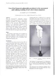
The Amputee Athlete<br />
by Richard Riley, CP.<br />
Figure 1. Below-knee amputee, George Lombard,<br />
member of the Fisher-Saloman Marathon Team<br />
and the U.S. Disabled Ski Team.<br />
An increasing number of amputees in the<br />
United States are moving beyond mere ambulation<br />
into active sports and recreation activities.<br />
Estimates of the number of amputees actively<br />
involved range from 15,000 to 20,000, with<br />
over 5,000 participating in organized competitive<br />
sports. 1<br />
Ten years ago, the athletic amputee was a<br />
unique phenomenon in our practice. Today few<br />
practitioners cannot count two or three among<br />
their clientele. These amputees are at the cutting<br />
edge of our field because they push us as<br />
professionals to expand our perceptions of what<br />
is possible. They also provide the positive role<br />
models that we hold out to the rest of our<br />
clients as an example of what can be done.<br />
The able-bodied sports world has taken some<br />
giant leaps of perception regarding the amputee<br />
athlete. No longer is it just "inspirational" to<br />
have a disabled person competing in sports.<br />
Today there are amputees that compete in<br />
world class events alongside the able-bodied.<br />
The skiing world has demonstrated this by<br />
naming below-knee amputee George Lombard<br />
to the Fischer-Saloman Marathon cross country<br />
ski team and awarding above-knee amputee<br />
Diana Golden with the U.S. Ski Writers Award<br />
for Outstanding Alpine Competitor.<br />
Not only are there more elite amputee athletes<br />
today, there is a much larger body of recreationally<br />
oriented amputees. The days are<br />
gone when the prosthetist and rehabilitation<br />
team could be satisfied with being able to get<br />
the amputee to just walk. Expectations of our<br />
clients have changed. Not only the younger<br />
amputee, but also the active geriatric expects<br />
to be able to ride a bicycle, play golf, tennis, or<br />
jog around the block. 2<br />
Our challenge is to meet<br />
these expectations.<br />
Psychology of the Amputee Athlete<br />
What causes one amputee to become an elite<br />
cross country skier (one of the most demanding<br />
physical sports in the world) and another with<br />
the same level of disability to be unable to even<br />
return to gainful employment? Part of the answer<br />
lies in the individual's ability to handle<br />
the stress and trauma of amputation. These are<br />
factors that we have little control over. The<br />
other part of the answer lies with environmental<br />
issues and can be addressed.<br />
Most amputee athletes are highly motivated<br />
individuals with a strong desire to overcompensate<br />
for their disability. A percentage of these
endorphines 4<br />
(the body's natural pain medication)<br />
into the body. These factors enable the<br />
amputee athlete to achieve great physical accomplishments.<br />
It also sets up potential for serious<br />
damage to the residual limb tissue because<br />
of overactivity. Pain is the body's message<br />
to the brain that something is wrong and<br />
many amputees have developed ways to shortcircuit<br />
this signal. This is a fact we must all be<br />
aware of in caring for and guiding the amputee<br />
athlete.<br />
Table I.<br />
people will rehabilitate themselves with practically<br />
no help at all and go on to accomplish<br />
great things in their personal lives as well as in<br />
sports. Others need the influence of role<br />
models to show them that their limitations are<br />
what they place upon themselves. One of the<br />
most positive experiences for any new amputee<br />
is when they meet another amputee with a positive<br />
attitude. 3<br />
This positive motivation is best<br />
facilitated by a support structure of family,<br />
friends, and the rehabilitation team. If any one<br />
of these aspects is continually placing limits on<br />
the amputee, eventually the amputee will accept<br />
these limitations. There are physical limitations<br />
for the amputee, but these should be discovered<br />
not imposed. There are ways around<br />
most physical limitations by keeping an open<br />
mind and being willing to innovate.<br />
Pain is an aspect of amputation that in many<br />
cases is initially the greatest barrier to overcome.<br />
All athletes know pain through training<br />
and the physical exertion of competition.<br />
People who are athletic prior to becoming an<br />
amputee will generally be able to deal with pain<br />
more easily due to their previous development<br />
of strategies to perform while enduring levels<br />
of pain. The successful amputee will develop<br />
ways of minimizing discomfort, either through<br />
increasing the conscious tolerance for pain or<br />
seeking a lifestyle that reduces trauma to the<br />
residual limb.<br />
The amputee athlete not only has the pain of<br />
general physical exertion to deal with, but also<br />
the added trauma of torques and stresses far<br />
beyond normal to the skin and bone structure of<br />
the residual limb. Most of these athletes have<br />
developed very high pain tolerances and their<br />
body readily reacts to pain stimuli by releasing<br />
Prosthetic Care<br />
For the prosthetic professional, the active<br />
amputee can be either a great source of pride<br />
and stimulation or a perpetual problem fraught<br />
with frustration. Nevertheless, this group of our<br />
clientele will continue to occupy a greater share<br />
of our patient load and we must develop strategies<br />
to successfully accommodate their needs.<br />
As important to the success of the athletic<br />
amputee as the prosthesis is his knowledge of<br />
how it works. Of equal importance are the limitations<br />
of the prosthesis and problem solving<br />
strategies for residual limb breakdown. The<br />
time spent in educating the amputee about his<br />
prosthesis and ways to deal with skin problems<br />
is always well spent.<br />
Regardless of how well fitting a prostheses<br />
is, there is a potential for skin breakdown of the<br />
residual limb due to overactivity. 5<br />
Athletes will<br />
continually push themselves to their limits and<br />
beyond. If they are armed with methods to deal<br />
with skin breakdown, they will benefit greatly.<br />
Advances in sports medicine for runners was<br />
bound to spill over into prosthetics. Of particular<br />
use is a skin protection material called<br />
"2nd Skin(tm)" (Table I). It is a 1/16" thick piece<br />
of gel that is applied directly onto the skin. It<br />
prevents friction between the skin and any<br />
moving surface. It does not stick to normal<br />
skin, yet because of its viscosity, will stay<br />
where it is placed. It is perforated so as to let<br />
the wound breathe as well as being sterile to<br />
prevent infection. 2nd Skin(tm) absorbs secretions,<br />
feels cool, alleviates itching, and can relieve<br />
pain. 6<br />
2nd Skin(tm) comes with plastic on both sides<br />
of the gel material. Before the plastic is removed,<br />
cut a piece one third larger than the<br />
area to be covered. This allows coverage of the
Figure 2. Applying 2nd Skin(tm) to a residual limb<br />
abrasion.<br />
affected area despite migration. The directions<br />
recommend removing the plastic from one side<br />
or from both sides. Personal experience has<br />
shown that removing the plastic from both<br />
sides prevents most migration.<br />
Because 2nd Skin(tm) is so thin, it does not<br />
increase pressure on blisters or abrasions. It<br />
prevents most friction and can actually promote<br />
healing even during heavy usage. 2nd Skin(tm)<br />
comes in a variety of sheet sizes which can be<br />
cut to the size needed and has to be kept in the<br />
zip-lock container provided. Unfortunately, it<br />
can be used only once and has to be cleaned off<br />
the sock after use. It works very well on<br />
below-knee amputees, especially when used<br />
beneath a sheath. In above-knee amputees,<br />
only suction wearers will experience difficulty<br />
in usage due to excessive migration from<br />
pulling into the socket. Second Skin® is an<br />
inert material made from 96 percent water and<br />
four percent polyethylene oxide.<br />
Another product which provides excellent<br />
friction reduction and is also reusable is<br />
"Spenco® Skin Care Pad" (Table I). This<br />
product comes in three thicknesses, 1/2", 3/16",<br />
and 1/8". The 1/8" thickness produces the least<br />
amount of pressure inside the socket. Spenco®<br />
Skin Care Pad acts like a second layer of fat to<br />
protect the skin from friction or abrasion. It adheres<br />
to the skin without sticking due to its viscosity.<br />
Made from a reticulated closed cell<br />
elastomer, it can be gas sterilized or washed in<br />
soap and warm water. It should also be stored<br />
in the zip-lock bag and has a shelf life of two<br />
years. It is best used as a preventative measure<br />
in circumstances where skin breakdown is a<br />
danger. 6<br />
One of the problems with most skin protection<br />
materials is that suction socket wearers<br />
cannot utilize them. When the amputee pulls<br />
into the suction socket, "2nd Skin(tm)" or<br />
"Spenco® Skin Care Pads" become displaced<br />
and usually do not cover the areas intended. A<br />
product that can be of use to suction socket<br />
wearers, or any amputee for that matter, comes<br />
with a variety of names. It is a transparent<br />
dressing with one adhesive side that is paper<br />
thin and porous both to air and water. The trade<br />
names are "Op-Site," "Bioclusive," "Tegaderm,"<br />
and "Acuderm" (Table I). This material<br />
can be applied directly to the skin and acts<br />
as another layer of protection, while still allowing<br />
normal dermal respiration and perspiration<br />
to occur. It can be left on the skin for four<br />
to five days before it needs to be removed. If<br />
left on much longer, the epidermis does not get<br />
an opportunity to slough off properly. 6<br />
These products work well to prevent friction,<br />
but do not provide any relief for pressure<br />
problems. The transparency of these materials<br />
allow for continual evaluation of the healing<br />
process. There is a problem that the adhesive is<br />
quite strong and oftentimes pulls hairs out upon<br />
removal. Different brands utilize different adhesives,<br />
but in general it is recommended that<br />
some soaking of the covered area in warm<br />
water will help remove the covering with minimal<br />
discomfort. Careful attention should be<br />
paid to the application instructions so as to<br />
avoid getting it adhered to itself when applying<br />
it. Most brands come with a paper backing and<br />
application method that allows it to be cut to<br />
the desired size.<br />
Until the time when skin abrasions and adherent<br />
scars become a thing of the past, we will<br />
have the need for skin protection materials.<br />
These products can give relief to thousands of<br />
prosthetic wearers as well as prevent much discomfort<br />
for active amputees. They should become<br />
a standard part of the amputee's "survival<br />
kit."<br />
Sports Organizations for Amputees<br />
The perceptions that amputees have of their<br />
capabilities has risen dramatically in the last<br />
decade. Paralleling the growth of competitive
Figure 3. The United States Disabled Ski Team.<br />
sports for amputees has been the organizations<br />
that provide the forum for these activities<br />
(Table II). Prior to these organizations bringing<br />
together amputees from around the nation and<br />
the world, there was little opportunity for exchange<br />
of ideas on the consumer level.<br />
Organizations such as the "National Handicapped<br />
Sports and Recreation Association,"<br />
sponsor and provide for competitive sports activities.<br />
Competition is based on ability and<br />
level of amputation with competitive levels<br />
ranging from local races to world class and a<br />
parallel Olympic structure.<br />
The impact of these organizations on the<br />
field of prosthetics has been enormous. All of<br />
us have fielded questions concerning amputee<br />
athletes and their various prostheses. This direction<br />
from the people whom we serve has<br />
been healthy for prosthetics for many reasons.<br />
First, we have had to expand our horizons and<br />
adapt technologies and techniques to accommodate<br />
these athletic amputees. Secondly, it has<br />
created a demand and thus a market for new<br />
components to accommodate extra-ambulatory<br />
activities. Third, there now exists a forum for<br />
amputees to exchange ideas, compare techniques,<br />
and services, as well as push each other<br />
to greater accomplishments. Another important<br />
contribution is the role model aspect of these<br />
athletic amputees. They provide inspiration to<br />
all of our clientele to continue to expand their<br />
perceptions of what is possible.<br />
All of these factors have changed prosthetics.<br />
Because of publicity surrounding some<br />
of the more astounding accomplishments, not<br />
only has the field gained more public recognition,<br />
but there is a growing acceptance of us as<br />
professionals. These organizations will continue<br />
to provide and promote sports and recreation<br />
as a normal part of the amputees lifestyle.<br />
Not only is it our responsibility and challenge<br />
to continue to adapt prosthetics to these activities,<br />
but it will play a major role in the future of<br />
our profession. 7<br />
Table II.
Conclusion<br />
As leisure time in our society increases, the<br />
need to accommodate sports and recreation in<br />
our society becomes essential. The perception<br />
of the amputee's lifestyle parallels this societal<br />
shift. Prosthetics must be able to accommodate<br />
this change in our patients' attitudes toward activity.<br />
This can best be accomplished through<br />
education and communication, as well as further<br />
development of componentry geared to the<br />
athletically inclined. 8<br />
The amputee athlete has given rise to a new<br />
specialty in our field. The sports prosthetist is<br />
now a viable specialist that as professionals we<br />
should recognize and refer our patients to. We<br />
will continue to provide state-of-the-art<br />
prostheses for our active amputees, and armed<br />
with information about proper care, they will<br />
be among the best athletes in the world.<br />
Author<br />
Richard Riley, CP., specializes in sports prosthetics and<br />
has a private practice with SportsMedicine Portsmouth, in<br />
Portsmouth, New Hampshire.<br />
Also a below-knee amputee, Riley is a member of the<br />
U.S. Disabled Nordic Ski Team and the Vice President of<br />
the National Handicapped Sports and Recreation Association.<br />
References<br />
1<br />
Riley, Richard, "The Amputee Athlete," Sports Medicine,<br />
Volume 4, October, 1984, pp. 31-32.<br />
2<br />
Kegel, Bernice, "Recreational Activities of Lower Extremity<br />
Amputees: A Survey," Archives of Physical Medicine<br />
and Rehabilitation, Volume 61, June, 1980, pp.<br />
258-264.<br />
3<br />
Foort, James, "How Amputees Feel About Amputation,"<br />
Orthotics and Prosthetics, Volume 28, March,<br />
1974, pp. 21-27.<br />
4<br />
Gaylor, Michael, M.D., personal communication,<br />
April, 1987. Presently Professor, Dartmouth College, Specialty<br />
in Sports Medicine.<br />
5<br />
Levy, W. S., "Skin Problems of the Leg Amputee,"<br />
Prosthetic and Orthotic International, Volume 4, 1980,<br />
pp. 37-44.<br />
6<br />
Riley, Richard, "Skin Protection Materials," lecture<br />
given at American Academy of Orthotists and Prosthetics<br />
Annual Meeting, Tampa, Florida, February, 1987.<br />
7<br />
Riley, Richard, "Sports Organizations for the Disabled<br />
and Their Impact on Prosthetics," lecture given at American<br />
Academy of Orthotists and Prosthetists Annual<br />
Meeting, Tampa, Florida, February, 1987.<br />
8<br />
Riley, Richard, "A Survey of Active Below-Knee<br />
Amputees," study undertaken at Northwestern Orthotic<br />
and Prosthetic Research Center, Chicago, Illinois, December,<br />
1980.<br />
9<br />
Kegel, Bernice, Sports for the Leg Amputee, 1986.
Winter Sports for the Amputee Athlete<br />
by Doug Pringle<br />
Organized participation in winter sports by<br />
people with disabilities has a relatively short<br />
history. It began in the early 1950s when amputee<br />
veterans of World War II began to experiment<br />
with skiing despite the loss of limbs. The<br />
West Germans are credited with the invention<br />
of the outrigger, a crutch with ski tips attached,<br />
which are used as balance assistors. This invention<br />
helped popularize the sport and several<br />
amputee ski clubs were formed in the United<br />
States.<br />
During the late 50s and early 60s, amputee<br />
skiing was the mainstay of the sport. It was<br />
during the late sixties and early seventies that<br />
others with one "bad" leg, such as polio<br />
victims, began to ski using the technique developed<br />
for amputees. It was also during this time<br />
that amputees began experimenting with skiing<br />
with a prosthesis.<br />
Simultaneously, visually impaired people<br />
began to participate and the sport began to include<br />
more than amputees. In the late 70s, the<br />
major innovation was development of the<br />
"Four-Track" technique, which allowed many<br />
types of severely disabled people to ski.<br />
The 1980s have contributed the technique<br />
known as 'sit skiing.' This technique allows<br />
people who are wheelchair bound to participate<br />
in the sport.<br />
The benefits of participation in skiing are numerous.<br />
Physically the participant develops<br />
stamina, strength, balance, and coordination.<br />
These are all valuable physical traits for a<br />
person trying to compensate for a physical<br />
problem.<br />
Psychologically, participants begin to develop<br />
a positive self-image and a "can do" attitude.<br />
This positive thought cycle carries over<br />
into other aspects of life such as education and<br />
employment.<br />
Skiing offers a unique opportunity as a sport<br />
that can be done with family and friends in a<br />
facility open to the public. In that sense it is a<br />
mainstreamed activity done with everyone else<br />
rather than in a special facility.<br />
Finally, there is something wonderful and<br />
invigorating about the freedom of movement,<br />
speed, risk, and the natural environment of<br />
skiing. All these add to the experience.<br />
Skiing is the only winter sport offered to<br />
people with disabilities through formal programs.<br />
These programs offer adaptive equipment,<br />
qualified instruction and a competition<br />
system. Participation in other winter sports is<br />
not extensive.<br />
Downhill Skiing<br />
Alpine<br />
Skiing<br />
Alpine (or downhill) skiing is the most popular<br />
winter sport of people with disabilities in<br />
the United States. There are approximately<br />
10,000 disabled skiers. The sport offers unique<br />
benefits to participants who are mobility impaired,<br />
not the least of which is that gravity<br />
supplies the means for movement.<br />
The development of adaptive equipment and<br />
techniques has made it possible for even the severely<br />
disabled to participate. Adaptive skiing<br />
is divided into five major categories or techniques:<br />
1. Three track skiing<br />
2. Four track skiing<br />
3. Blind skiing<br />
4. Sit skiing<br />
5. Other adaptive techniques
Three Track Skiing<br />
Above-knee and below-knee amputees,<br />
persons with polio or birth defects, and those<br />
with a variety of other problems, ski three track<br />
in which the common element is having one<br />
good leg and two good arms. Above-knee amputees<br />
ski without their prosthesis because it is<br />
difficult to control. Below-knee amputees can<br />
ski with their prosthesis. The advantage is that<br />
they can stand on it when stopped. The disadvantage<br />
is increased risk of injury.<br />
Adaptive equipment for three trackers are<br />
outriggers. Outriggers are forearm crutches<br />
with ski tips attached. They act as balance assistors<br />
and are used to "walk" on the flats.<br />
Three track skiing derives its name from the<br />
three tracks made in the snow by two outriggers<br />
and the single ski.<br />
Some three trackers, especially racers, learn<br />
to ski with ski poles instead of outriggers. In<br />
fact, that is how people with one leg skied before<br />
the invention of outriggers. While more<br />
difficult, "one tracking" is also a possibility<br />
for many and skiing with poles is an advanced<br />
instructional method.<br />
Four Track Skiing<br />
Four track skiing is used by people with a<br />
wide variety of disabilities including: double<br />
leg amputees, spina bifida, cerebral palsy,<br />
muscular dystrophy, multiple sclerosis, stroke,<br />
head trauma, paraplegia, and polio. An individual<br />
with two legs and arms, natural or prosthetic,<br />
who is capable of standing independently<br />
(static balance), or with the aid of outriggers,<br />
could use this method. Many severely<br />
disabled people ski using this technique.<br />
In addition to outriggers, a lateral stability<br />
device is often used. This device is commonly<br />
referred to as a "ski bra." It helps keep the<br />
skiis parallel and also allows the student's<br />
strong side to help control the weaker side.<br />
Blind Skiing<br />
Visually impaired students are taught the<br />
same as any other skier with the exception that<br />
the instructor must learn to communicate more<br />
clearly. A number of holds or assists have been<br />
developed as well. Once the student can ski,<br />
the task becomes one of guiding or talking<br />
them down the hill.<br />
No adaptive equipment is required for the visually<br />
impaired. Often the student and instructor<br />
(or guide) wear bright bibs which<br />
signal to other skiers to be alert.<br />
Sit Skiing<br />
Sit skiing is the technique used by anyone<br />
who cannot ski standing. Sit skiers include<br />
people with muscular dystrophy, multiple sclerosis,<br />
cerebral palsy, spina bifida, paraplegia,<br />
and quadraplegia. This technique has been used<br />
since 1980 and it has opened skiing to people<br />
who are wheelchair bound.<br />
The sit ski has a fiberglass shell and metal<br />
edges. It is steered by leaning the body and by<br />
dragging a "pole" on the side to which the<br />
skier wants to turn. An instructor skies behind<br />
the device holding a length of nylon mesh cord<br />
in order to stop the skier and to assist with turns<br />
when necessary. Sit skiers often become proficient<br />
enough to ski "untethered" or without<br />
the instructor and safety line.<br />
The most recent development in sit skiing is<br />
the mono-ski. Here the fiberglass shell is<br />
mounted on a single ski and the skier uses outriggers.<br />
Use of a mono-ski requires good upper<br />
body strength. Therefore, it is a technique that<br />
is not suitable to quadraplegics and high-level<br />
paraplegics.<br />
Other Adaptive<br />
Techniques<br />
This catch-all category is used for a variety<br />
of people with disabilities who don't fit into<br />
any of the other four. Among them are upper<br />
extremity impairment: people who have lost the<br />
use of one or both arms. Those with one good<br />
arm use one ski pole and a pole can also be<br />
used with an arm prosthesis.<br />
Below-knee amputees may choose to ski<br />
using their artificial leg or legs. A heel line is<br />
usually necesary to achieve a bent knee position.<br />
Waist straps and thigh lacers help provide<br />
lateral stability, a snug fit, and reduced pistoning<br />
and rotation. A special ski leg can be<br />
made if the student decides to seriously pursue<br />
skiing.<br />
The combination of disabilities and adaptive
equipment are numerous. In competitions,<br />
some 19 different classes are recognized. But,<br />
generally, most people ski using one of the four<br />
major techniques.<br />
Instruction<br />
There are a number of programs of ski instruction<br />
available. Most are voluntary,<br />
weekend programs. There are five full-time<br />
professional ski schools which specialize in<br />
adaptive skiing and about 25 voluntary ones.<br />
All but a few of these programs are chapters or<br />
affiliates of the National Handicapped Sports<br />
and Recreation Association (NHSRA).<br />
The NHSRA has also developed a clinic<br />
team which trains instructors in adaptive ski<br />
teaching. The team also advises on program delivery.<br />
There is an instructor testing and certification<br />
program conducted by NHSRA which is<br />
approved and recognized by the Professional<br />
Ski Instructors of America.<br />
Competition<br />
A natural outgrowth of participation in sports<br />
is the development of competition. A very well<br />
developed system is in place. Learn to Race<br />
clinics and training camps are conducted by a<br />
few of the instructional programs locally and<br />
by the NHSRA nationally.<br />
Those interested in competition can race in<br />
any number of programs open to the public<br />
such as NASTAR and United States Ski Association<br />
races. Further, there are ten sanctioned<br />
regional championships at which racers can<br />
qualify for the nationals.<br />
Both the NHSRA and U.S. Association of<br />
Blind Athletes conduct annual national championships.<br />
Both organizations also select athletes<br />
for the U.S. Disabled Ski Team which competes<br />
in the World Winter Games for the Disabled<br />
and the Winter Olympics for the Disabled.<br />
In 1986, the U.S. Disabled Ski Team was<br />
number one in the world at the games in<br />
Sweden.<br />
Resources<br />
National Handicapped Sports and Recreation<br />
Association<br />
4405 East West Highway, Suite 603<br />
Bethesda, MD 20814<br />
U.S. Association of Blind Athletes<br />
Professional Ski Instructors of America<br />
5541 Central Ave.<br />
Boulder, CO 80301<br />
Alpine Skiing, contact:<br />
Vineland National Center<br />
P.O. Box 308<br />
Loretto, MN 55357<br />
Nordic Skiing<br />
Nordic (or cross country) skiing is also popular<br />
among people with disabilities. Since the<br />
sport does require more muscular effort for motion<br />
than Alpine skiing, it is not an option for<br />
some severely disabled individuals.<br />
Among the participants are amputees skiing<br />
with their prosthesis and some who ski on one<br />
leg. Those on one leg must rely upon upper<br />
body strength and use their poles to push themselves<br />
along.<br />
Nordic skiing is well suited for the visually<br />
impaired. They may ski with a guide or follow<br />
pre-set tracks in the snow.<br />
Some more severely disabled people who<br />
would be four-trackers in Alpine skiing, such<br />
as those with cerebral palsy, muscular dystrophy,<br />
multiple sclerosis, stroke, head injury,<br />
etc., can also participate in Nordic skiing if<br />
they are able to ambulate well. Some will require<br />
assistance, pushing or pulling with a<br />
rope, and frequent rest breaks are always a safe<br />
practice.<br />
There is a sit ski for Nordic skiing. The sit<br />
skier will need excellent upper body strength to<br />
push themselves over any appreciable distance.<br />
Again, assistance and rest stops will help.<br />
Instruction<br />
There are very few Nordic skiing instructional<br />
programs in the U.S. The sport is just<br />
beginning to develop. Those interested in<br />
learning the sport should check with a local<br />
cross country ski resort to see if they have an<br />
instructor willing and qualified. Most will have<br />
difficulty finding a program nearby.
Competition<br />
The competition program described under<br />
Alpine skiing exists for Nordic skiing. Nordic<br />
events are held separately from Alpine events,<br />
but the U.S. Disabled Ski Team includes both<br />
Alpine and Nordic competitors.<br />
Other Winter Sports<br />
Snowmobiling has been a sport in which<br />
people with disabilities have participated for at<br />
least 15 years. It was one option open to more<br />
severely mobility impaired individuals before<br />
development of four track and sit skiing.<br />
Ice boating and bike sailing are adaptable to<br />
a wide variety of mobility impairments. Ice<br />
fishing can also be enjoyed by many people.<br />
Author<br />
Doug Pringle is the past president of the National Handicapped<br />
Sports and Recreation Association, 5946 Illinois<br />
Avenue, Organeville, California 95662.
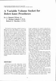
The UCLA Total Surface Bearing<br />
Suction Below-Knee Prosthesis<br />
by Timothy B. Staats, M.A., CP.<br />
Judd Lundt, B.S., A.E.<br />
Introduction<br />
While there was clear evidence to support<br />
examination of suction as a suspension technique<br />
for below-knee prostheses 1<br />
in the early<br />
1950s, overwhelming activity was in a direction<br />
that led ultimately to the development of<br />
the PTB design. 2<br />
What is truly remarkable is<br />
the almost blind obedience that the practitioners<br />
and educators have given to PTB theories, a<br />
recognition that has rendered them all but untouchable<br />
gospel. Introduction and widespread<br />
use of transparent check sockets has probably<br />
done more to cause the prosthetist to question<br />
the accuracy of his PTB fitting methods than<br />
any other development in the last decade. Inaccuracy<br />
in socket fit that this powerful tool has<br />
revealed has led to the obvious conclusion:<br />
more precise casting and modification methods<br />
are required. This is the intent of the technique<br />
described here.<br />
This paper presents a departure from PTB<br />
philosophy and technique. The methods described<br />
freely borrow from and recognize individuals<br />
who have developed alternative ideas,<br />
many of which have been integrated into the<br />
UCLA Total Surface Bearing Suction Below-<br />
Knee Prosthesis. The substance of this paper<br />
includes suction as the obvious mode of suspension.<br />
However, the essence of suction suspension,<br />
and of this article as well, is the critical<br />
anatomical accuracy of the socket fit. We<br />
refer to it as the total surface bearing or TSB<br />
technique. Without TSB, successful long-term<br />
suction suspension cannot be achieved. With<br />
TSB, the prosthetist can achieve suction if desired<br />
or may choose to fit with a sock and<br />
without suction if so indicated. Whatever the<br />
case, the final result will be improved fit and<br />
better patient comfort.<br />
Suction Suspension<br />
Suction below-knee prostheses are unique in<br />
that they do not require auxiliary suspension<br />
systems such as straps, cuffs, thigh lacers, or<br />
sleeves to maintain the socket on the residual<br />
limb. This is not to suggest that auxiliary suspension<br />
need not be employed as an extra measure<br />
of protection, particularly with a very active<br />
patient. However, in principle no other<br />
suspension should be required (Figure 1).<br />
Three variations of suction socket are discussed<br />
in this article. The first is the "tension<br />
suction" variation. 3 , 4,5<br />
This socket is made volumetrically<br />
smaller than the residual limb. Suction<br />
is maintained in the same manner as with<br />
the rigid above-knee suction prosthesis. This is<br />
probably through tension placed on the skin,<br />
thereby enhancing the friction between the<br />
tissue and the socket. Normally, a valve is<br />
placed at the distal end to release air while the<br />
socket is being applied. The second classification<br />
is "atmospheric suspension," mentioned<br />
by Murphy 6 in 1950 and later by others. 7 In<br />
atmospheric suspension, a non-elastic, but<br />
flexible interface is used, which virtually collapses<br />
around the residual limb when the prosthesis<br />
is unweighted. The third type of suction<br />
will be called "active compression suction." In<br />
this case, the socket interface is made of an<br />
elastic or elastomeric material which must be<br />
stretched or rolled over the residual limb,<br />
thereby gripping the skin through compression<br />
as well as through friction created between the<br />
skin and the socket. 8
A suction below-knee prosthesis virtually<br />
eliminates skin problems caused by movement<br />
and friction created between the residual limb<br />
and the socket interface. Problems of skin irritation<br />
related to hygiene and allergic reaction<br />
are covered in a later section.<br />
Bony<br />
Prominences<br />
Grevsten, 10<br />
using x-ray evaluation of suction<br />
below-knee fittings, found that the movement<br />
of skeletal anatomy inside the socket is less<br />
than one-half that inside ordinary PTB sockets.<br />
The UCLA experience, which employs a more<br />
intimate casting and cast modification technique<br />
(TSB), suggests an even greater reduction<br />
in skeletal movement. More importantly,<br />
few problems with bony prominence pain or<br />
discomfort were reported by patients in the<br />
over 150 fittings conducted at UCLA and other<br />
locations during the teaching of this technique.<br />
Figure 1. UCLA Total Surface Bearing Suction<br />
Prostheses.<br />
Fitting Variables<br />
The primary concern of any prosthetist attempting<br />
to fit a suction below-knee prosthesis<br />
should be the general health of the residual<br />
limb tissues. The UCLA experience has been<br />
similar to studies by Holmgren 9 and Bedouin. 4<br />
Types of Patients<br />
The suction below-knee prosthesis, properly<br />
fitted, appears to stimulate circulation and can<br />
be used on vascular amputees as well as amputations<br />
due to other causes. The suction belowknee<br />
may actually help to more quickly stabilize<br />
tissue fluid volume. Ages of patients have<br />
ranged from five to 88 years.<br />
Skin<br />
Problems<br />
Length<br />
We have found no correlation between residual<br />
limb length and the ability to wear a suction<br />
below-knee prosthesis. Fittings and suction<br />
suspension have been successfully achieved<br />
with residual limb lengths as short as 3 1/2".<br />
However, these are not all long-term results.<br />
Volume<br />
More important was the finding that many<br />
residual limbs initially fit with suction would<br />
lose this effect within one or two hours of wear.<br />
There is an immediate fluid volume adjustment.<br />
Patients fit with suction over longer periods<br />
of weeks and months will continue to experience<br />
residual limb volume changes until a<br />
point of volume stability is achieved. This normally<br />
will occur within six weeks. Any loss of<br />
body weight will certainly contribute to loss of<br />
suction as well.<br />
Shape<br />
Generally, with enough effort almost any<br />
shape residual limb can be fit with suction.<br />
However, to achieve suction with conical shape<br />
residual limbs, whether bony or fleshy, can be<br />
difficult. With such cases, it is often necessary<br />
to enlarge the gastrocnemius muscle bulge area<br />
of the socket while tightening slightly proximal<br />
to this to maintain suction. Many prosthetists<br />
might question the long-term effect of this technique<br />
on the health of the residual limb. Short
term effects have not been adverse and results<br />
look encouraging.<br />
Patient<br />
Cooperation<br />
Patients who intend to wear suction belowknee<br />
prostheses must be intelligent, cooperative<br />
and aware of the critical nature and accuracy<br />
required in this type of fitting. Numerous<br />
adjustments may be required during the first<br />
several months to maintain the intimacy of the<br />
fit. The patient must fully understand the function<br />
of the valve and the socket liner. It is imperative<br />
that any patient wearing a suction<br />
below-knee prosthesis, no matter how effectively<br />
fit, wear an auxiliary suspension as a<br />
back-up in case loss of suction does inadvertently<br />
occur.<br />
Comparison of Theories<br />
In the below-knee prosthesis, suction is a<br />
mode of suspension that can only be maintained<br />
through a precisely fit socket. A major<br />
aim of this article is to present a technique<br />
whereby such a fit can be achieved. Development<br />
of the total surface bearing (TSB) belowknee<br />
socket combines a staged precision<br />
casting method with a significantly different<br />
model modification to yield this result. In order<br />
to understand these differences, it is necessary<br />
to contrast the TSB and the more traditional<br />
PTB sockets.<br />
The basic philosophy of the patellar tendon<br />
bearing below-knee prosthesis can be stated as<br />
follows: Increase weight bearing on areas of the<br />
residual limb over pressure tolerant areas and<br />
relieve pressure over those areas which are<br />
pressure sensitive. With the total surface<br />
bearing below-knee prosthesis weight is distributed<br />
over the entire surface of the residual<br />
limb, including areas which have in the past<br />
been considered pressure sensitive. In TSB, the<br />
accuracy of fit and careful use of measurements<br />
has eliminated the need for relief buildups over<br />
bony areas of the residual limb during the<br />
plaster casting and model modification procedures.<br />
The resulting corrected model for a TSB<br />
socket is thus distinctly different from that developed<br />
in accordance with PTB modification<br />
techniques.<br />
Evaluation and Measurement<br />
Measurements include all standard belowknee<br />
prosthetics parameters. The following additional<br />
considerations are necessary.<br />
Circumferences<br />
Carefully located circumferential measurements<br />
are taken at one inch intervals. The intervals<br />
are laid out from a bony landmark<br />
which can be defined accurately during the<br />
plaster casting procedure. Normally, the apex<br />
of the head of the fibula or the distal anterior tip<br />
of the tibia are chosen, depending on which is<br />
more prominent. The tibial tubercle may also<br />
be used. However, it is necessary to measure at<br />
least one interval more proximal when this location<br />
is chosen. In very fleshy or redundant<br />
residual limbs, it is wise to select the fibular<br />
head as some elongation may occur during<br />
casting which will obscure the distal end.<br />
Length<br />
The length measurement must be accurately<br />
gauged from the distal end of the residual limb<br />
to both the medial tibial plateau and to the inferior<br />
edge of the patella while under forceful upward<br />
loading.<br />
Evaluation<br />
Patients with chronic skin problems or burn<br />
scar tissue may not be suitably fit in sockets<br />
where the skin is directly in contact with the<br />
socket liner, unless the interface surface is impervious<br />
to body fluids. Perspiration can cause<br />
maceration even in healthy skin and an appropriate<br />
interface must be selected in such cases.<br />
Plaster Casting Technique<br />
An essential element of a successful TSB<br />
socket is a precisely cast residual limb. The diagonal<br />
four stage casting technique which<br />
draws from work adapted from Fillauer, 11<br />
Gleaves, 12 Tranhardt, 13 Morris, 14 Hayes, 15<br />
Stokosa, 16 and Vinnecour 17 was developed to<br />
best achieve that end. Unusual elements of the<br />
technique include:<br />
1. Sheer nylon stockings for an ultra-thin<br />
barrier between skin and plaster, resulting<br />
in a more accurate cast.
Figure 2. The entire medial tibial flare and all<br />
bony prominences are carefully molded.<br />
2. A beveled anterior first stage splint which<br />
is very accurately tailored to encompass<br />
the head of the fibula, the shaft of the<br />
tibia, and the entire medial flare. This<br />
first stage (Figure 2) is carefully molded<br />
to all bony anatomical structures. If properly<br />
applied, it will establish the mediolateral<br />
dimension within 1/8" of patient<br />
measurement in most situations and require<br />
little or no model modification of<br />
the anterior aspect of the medial flare of<br />
the tibia.<br />
3. A second stage of elastic plaster bandage<br />
which is wrapped with about half the<br />
available stretch applied. This stage must<br />
not extend more proximal than about 1"<br />
to 1 1/2" below the crease of the skin in the<br />
popliteal fold. The anterior stage is maintained<br />
in position during this second procedure<br />
with firm proximal compression.<br />
As the second stage sets, the proximal<br />
posterior aspect is lightly compressed to<br />
help define the antero-posterior dimension<br />
of the cast. The medial lateral dimension<br />
is never sacrificed in any attempt<br />
to decrease the antero-posterior dimension.<br />
4. A third stage splint, which creates the<br />
posterior brim shape and completes the<br />
basic cast used when a non-supracondylar<br />
trim line, is desired. The salient point of<br />
the third stage is the hand molding of the<br />
plaster bandage in the hamstring tendon<br />
Figure 3. The posterior trim and hamstring<br />
muscle reliefs are created during the wrap casting<br />
procedure.<br />
region. When properly applied, the posterior<br />
brim will appear premodified with a<br />
diagonal trim which accommodates the<br />
lower anatomical insertion of the medial<br />
hamstring muscle group. It is necessary<br />
to do four things simultaneously to create<br />
an acceptable third stage, and generally<br />
will take considerable practice before repeatable<br />
accuracy and skill is achieved. It<br />
is necessary first to locate and create the<br />
shape of the tendons; secondly, compress<br />
the antero-posterior dimension of the<br />
cast both proximally and compressionally;<br />
third, mold the medial and lateral<br />
posterior areas of the third stage to prevent<br />
looseness in the hamstring areas<br />
proximal to the medial tibial plateau region;<br />
and fourth, spread the fingers of<br />
both left and right hands to stretch the<br />
plaster bandage to prevent a ridge from<br />
forming in the posterior aspect between<br />
the second and third stages (Figure 3).<br />
5. A fourth stage splint is used when supracondylar<br />
suspension is planned. It is applied<br />
in a manner similar to that used in<br />
Fillauer's three stage casting technique.
Figure 4. The wrap cast is alginated and pressure<br />
fitted.<br />
Alginate Pressure Fitting<br />
The first step in the fitting process occurs immediately<br />
after the hardened cast is removed.<br />
Through application of dental alginate to the<br />
inside of the wrap and a refitting on the patient,<br />
a more intimate contour is achieved. Though<br />
somewhat of a messy procedure, this will minimize<br />
the need to remove plaster from the model<br />
during modification. When casting very obese<br />
patients or those with excessive redundant<br />
tissue, this step may not be successful and may<br />
result in distortions in the final model.<br />
The nylon stockings are carefully removed<br />
from the cast and a hole is cut in each of the<br />
distal, lateral, medial, and posterior aspects to<br />
permit air to escape when the alginate is applied.<br />
The holes should be approximately 1/4" in<br />
diameter and should be cut using a knife. (A<br />
hand drill or drill press will likely grab the<br />
fabric in the wrap and destroy it.) About eight<br />
to ten ounces of dental alginate are mixed to a<br />
thick, but creamy consistency and quickly applied<br />
to the entire inner surface. The cast is replaced<br />
on the residual limb and forced proximal<br />
with moderate pressure. Alginate should exude<br />
from all cut holes (Figure 4).<br />
The instant the alginate stops flowing from<br />
the holes, they are covered with the hands or<br />
fingers to prevent further leakage. Any excess<br />
alginate can be smeared about the proximal<br />
brim to perfect the fit in this area (Figure 5).<br />
Figure 5. The completed diagonal four stage wrap<br />
cast.<br />
This procedure must be conducted quickly and<br />
precisely or air pockets will occur. If air<br />
pockets do occur, we have found that additional<br />
algination attempts have been unsuccessful.<br />
Total Surface Bearing<br />
Model Modification<br />
The antero-posterior and medial lateral are<br />
modified exactly to residual limb measurements.<br />
The anterior modification of the anteroposterior<br />
is markedly different from the PTB<br />
"Bar." The TSB modification follows the<br />
shape of the anatomy in this region as shown in<br />
the xeroradiograph of the below-knee amputation<br />
(Figure 6).<br />
Notice that the shape of the tibia angles posteriorly<br />
immediately above the tibial tubercle.<br />
Plaster removal follows this shape. The inferior<br />
edge of the patellar area is modified as though<br />
the patella were being lifted proximally about<br />
1/4". In other words, the true tibial plateau is<br />
below the inferior edge of the patella in most<br />
cases (Figure 7). The posterior aspect of the<br />
model normally requires only smoothing or<br />
only slight reduction to establish the correct<br />
AP.<br />
Plaster is removed from the posterior aspect<br />
of the medial flare of the tibia. This half moon<br />
shape sweeps into the medial hamstring area.<br />
Up to 3 /8" of plaster may be removed in a very<br />
redundant residual limb. It is not unusual to see<br />
a medial hamstring 1/2 to 3 /4" lower than the
Figure 6. Xeroradiographs lateral view of belowknee<br />
amputation. Notice the shape proximal to<br />
tibial tubercle.<br />
lateral side. Generally, the lateral side hamstring<br />
can be kept almost at tibial plateau level<br />
and is maintained at this level across the popliteal<br />
fossa.<br />
Absolutely no buildups are applied to the<br />
crest of the tibia, the head of the fibula, the<br />
anterior distal aspect of the tibia, or any other<br />
bony prominences. Reliefs are created by removal<br />
of plaster from around these areas to accentuate<br />
their shapes and to compress the<br />
tissues. Usually no more than 1/8" of plaster is<br />
carved away using a curved blade flexible knife<br />
(Figure 8).<br />
The model is next measured for circumferences<br />
using the previously established bony<br />
landmark as a guideline for accurately locating<br />
the measurement levels (Figure 9).<br />
It is generally found that the model at this<br />
point will be approximately at the residual limb<br />
measurement or somewhat larger, even if fairly<br />
liberal modifications have been performed. If<br />
the model were to be smoothed and a socket<br />
fabricated at these measurements (0" to +1/8")<br />
it will result in about a two-ply heavy cast sock<br />
fit or about one "Socket Liner Stump Sock." 18<br />
However, this may not in itself achieve suction.<br />
In order to create a suction fit, the model<br />
must be carefully reduced in its circumferential<br />
measurements starting from a point approximately<br />
one inch above the tibial plateau and<br />
proceeding distally the entire length of the cast.<br />
As a beginning, a minimum of 1/2" of tension<br />
reduction less than the patient's measurements<br />
is applied at each measured level. Ultimately,<br />
in a new patient (any patient who has never<br />
Figure 7. Modification inferior to patella simulates<br />
shape of anatomy rather than "PTB" patellar<br />
bar.<br />
Figure 8. No plaster buildups are added to master<br />
model. Plaster is carefully removed around bony<br />
prominences and over bony prominences.
Figure 9. Circumference measurements of master model are reduced below patient measurements to<br />
achieve suction.<br />
worn a suction socket) the tensions may well<br />
reach 3/4" to 1" less than the original anatomical<br />
measurements. However, it is not a simple<br />
matter of initially bringing the tensions on the<br />
model to these values. This is inadvisable and<br />
potentially harmful for the patient. A gradual<br />
reduction process over time must be followed<br />
in order to achieve the results just stated.<br />
In pilot studies and in pilot courses conducted<br />
at UCLA in 1984, an attempt to empirically<br />
arrive at appropriate TSB suction tension<br />
values was made. Each prosthetist was asked to<br />
carefully record how much reduction in residual<br />
limb measurements was required to finally<br />
achieve suction suspension. The compiled<br />
results of these efforts suggest an initial tension<br />
value of 3/4" is necessary at each level to<br />
achieve suction. This value may vary depending<br />
on residual limb musculature, length,<br />
and tissue type.<br />
The Flexible Check Socket<br />
A check socket is vacuum formed using 1/8"<br />
Surlyn® plastic. On a five to seven inch residual<br />
limb this will result in a very thin socket<br />
probably no thicker than 1/32". A valve is located<br />
distally to release air from the socket as it<br />
is donned (Figure 10).<br />
Check Sockets<br />
It is advisable, if not imperative, to use<br />
transparent check socket fittings to confirm the<br />
accuracy and precision of the wrap cast and<br />
subsequent model modifications. The UCLA<br />
technique involves two types of check sockets:<br />
flexible check sockets and more conventional<br />
rigid check sockets.<br />
Figure 10. A flexible check socket is vacuum<br />
formed with small valve placed distally.
Figure 11. The flexible check socket is "wet" fit<br />
to the patient.<br />
Figure 12. Suction, total contact, volumetric and<br />
anatomic accuracy of check socket are determined<br />
in the flexible check socket.<br />
Lotion or Vaseline® is used to lubricate the<br />
surface of the residual limb to aid in donning 19<br />
(Figure 11). Flexible socket fit can be confirmed<br />
by direct palpation of the anatomy from<br />
the outer surface. Any air spaces or otherwise<br />
loose areas are located and subsequently corrected<br />
on the model. It is not unusual for this<br />
flexible socket to hold suction even if inadequate<br />
tensions were applied to the model<br />
(Figure 12).<br />
Accordingly, if the socket is made rigid by<br />
an application of a roll of fiberglass casting<br />
tape to the outer surface, suction will invariably<br />
be lost almost immediately. This demonstrates<br />
one of the many problems facing anyone<br />
wishing to fit or wear a suction below-knee<br />
prosthesis. The flexible socket in this case is<br />
exhibiting atmospheric suction. The socket collapses<br />
around the residual limb as any attempt<br />
is made to remove it. Rendering the socket<br />
rigid transforms this flexible membrane into a<br />
rigid socket and as the socket wall cannot<br />
move, suspension is lost.<br />
The Rigid Check Socket<br />
A rigid check socket may be used after the<br />
model corrections, determined by the fit of the<br />
flexible check socket, have been performed.<br />
With the rigid fitting, it is common to find the<br />
need to increase tension values to an average of<br />
5<br />
/8" to 3 /4". It must be assumed that fluids rapidly<br />
leave the residual limb as a more rigid, accurate<br />
fitting socket is applied. It might also be<br />
speculated that the muscles flatten out somewhat<br />
as excess fluid leaves the residual limb.<br />
Examination of residual limbs in properly fit<br />
rigid transparent suction check sockets after<br />
several hours of wear reveal good color and<br />
lack of a distal discoloration which one might<br />
expect in a "tight" socket.<br />
Socket Materials<br />
A variety of materials and fabrication techniques<br />
have been examined for their application<br />
to the suction socket. Varying levels of success<br />
have been achieved; however, there are usually<br />
trade-offs involved. Suction may be achieved<br />
with a removable liner/insert alone that keys<br />
into the prosthesis much like a liner in a PTB<br />
socket. A prosthesis may also be constructed<br />
with a hard suction socket with no liner or with<br />
a soft liner that is permanently attached. In any<br />
case, some type of valve is usually necessary,<br />
installed either in the liner, in the socket, or at<br />
the end of a tube extending from the distal end<br />
of the socket to the outside finish lamination of<br />
the prosthesis. Valveless liners are also possible;<br />
they will be discussed later.<br />
In considering a method of constructing a<br />
suction socket, it is important to realize that<br />
there will be no sock to absorb moisture; the<br />
patient will likely require some type of powder,<br />
cream or lotion application to don the socket,<br />
and the skin will be in direct and intimate contact<br />
with the inner material. All of these factors<br />
dictate a non-porous, easily cleaned material<br />
that will minimize the growth of bacteria, yet<br />
provide the necessary cushioning and comfort<br />
for daily or specialized activities. Whichever<br />
approach is taken, the prospects of success are<br />
limited only to the ingenuity of the prosthetist<br />
and the materials employed.
Hard Socket<br />
Variations<br />
This is perhaps the most difficult variation<br />
with which to achieve success since the demands<br />
of precision required for fit and comfort<br />
are the highest. Firm residual limbs of good<br />
muscle mass are the most likely candidates for<br />
this design.<br />
The hard socket is undoubtedly the easiest to<br />
fabricate, and for the patient is the easiest to<br />
keep clean. Even if accepted by the patient,<br />
these sockets will feel hard and, while suitable<br />
for walking, they are probably not appropriate<br />
for heavy activities such as running. However,<br />
hard sockets, with the addition of a single<br />
nylon sheath, have been very successful in the<br />
long-term with low activity level patients.<br />
Flexible acrylic and polyester laminates backed<br />
on the outer surface with soft foams such as<br />
PE-LITE(tm) or Aliplast(tm) have enjoyed about<br />
the same level of success as a hard socket. Patients<br />
report that these sockets feel hard despite<br />
the padding. Additionally, allergic skin reactions<br />
seem to be more common when flexible<br />
resins are used. Minute cracking in the interface<br />
may create a breeding ground for bacteria<br />
or lead to skin irritation through surface friction.<br />
A number of thermoplastic liners have been<br />
successfully fit (Figure 13). Some have been<br />
quite comfortable, notably the "total flexible<br />
brim" variation suggested by IPOS 20<br />
and Sabolich.<br />
7<br />
Both are frame-supported polyethylene<br />
designs. Since thermoplastics may exhibit<br />
"cold flow" and may actually shrink, they are<br />
not ideal materials. An interesting characteristic<br />
of thin thermoplastic sockets is the enhanced<br />
capability of atmospheric suction.<br />
However, this advantage is basically negated<br />
by a lack of long-term durability. The suggested<br />
ease of refabrication and/or inexpensive<br />
nature of replacement does not hold up to criticism<br />
by patient used to no-nonsense prosthetic<br />
care. Another negative characteristic of thin<br />
thermoplastic liners such as Surlyn® and polyethylene<br />
is the inability to make adjustments<br />
after fabrication.<br />
A major point of consideration in fitting any<br />
socket material that directly contacts the skin is<br />
the coefficient of friction at the interface. There<br />
are definite differences which are recognized<br />
empirically and clinically, but not objectively<br />
related to prosthetic fit in the below-knee as<br />
Figure 13. Surlyn® inner flexible socket with<br />
outer frame fitted in 1985 as a suction below-knee<br />
prosthesis.<br />
well as in above-knee suction sockets. For example,<br />
Surlyn® and Durr-Plex both seem to<br />
have a surface which adheres very well to<br />
slightly damp skin. When these surfaces are<br />
lightly sanded, they lose some of this gripping<br />
capability. This can be both a positive and a<br />
negative factor, depending on the skin tolerance<br />
of the patient involved.<br />
Generally, hard socket variations of suction<br />
below-knee prostheses, while feasible, are not<br />
very practical for most patients. Moreover, the<br />
instance of inadvertent loss of socket suction<br />
must be expected. This is not really considered<br />
a problem since we recommend that auxiliary<br />
suspension be worn even on the best suction<br />
below-knee fitting.
Figure 14. Pelite(tm) liner with Plastozote distal<br />
end, distal valve and Surlyn® outer shell fitted as<br />
suction below-knee prosthesis in early suction<br />
below-knee courses at UCLA in 1985.<br />
Figure 15. The TSB Suction below-knee can be<br />
fitted on almost any length below-knee residual<br />
limb. Auxiliary suspension is not shown in this<br />
diagram but is recommended for all suction<br />
below-knee wearers.<br />
Soft Socket<br />
Variations<br />
Early suction liners were made of leather<br />
backed with Neoprene(tm). Even when given a<br />
sealant coating, the leather will begin to deteriorate<br />
and develop offensive odors in a fairly<br />
short period. However, good comfort has been<br />
achieved as has adjustability. Replaceability is<br />
not really possible in this variation.<br />
PE-LITE(tm) and Surlyn®-backed PE-LITE(tm)<br />
have both been successfully used for soft suction<br />
liners (Figures 14 and 15). It wears fairly<br />
well and can be cleaned with baking soda, vinegar,<br />
or rubbing alcohol to eliminate both odor<br />
and dirt. These liners will likely pack-out in<br />
time, and thus, normal prosthetic delivery<br />
should include a duplicate. Replacement duplication<br />
after wearout of thermoplastic foam<br />
liners is not really practical to the level of precision<br />
necessary to maintain suction.<br />
Another major advantage of these materials<br />
is that they may be easily added to or otherwise<br />
adjusted. By use of selectively placed materials<br />
of varying durameters, comfort can be achieved<br />
in very bony patients and those with poor skin<br />
conditions. It is important to further note that<br />
some foams are not closed cell and will, therefore,<br />
permit moisture, dirt, and bacterial<br />
buildup which may not be easily removed.<br />
However, coatings have been developed which<br />
may solve the interface cleansing problem. Additional<br />
considerations in the use of a liner<br />
coating are potential allergic reactions, alteration<br />
of friction and shock absorption charac-
teristics of the liner material, and adequacy of<br />
adherence.<br />
Foam liners, it must be remembered, provide<br />
comfort by absorbing load forces of axial,<br />
shear, and torque. The shock of impact is absorbed<br />
in the compression of the foam or in the<br />
compression of the gases within the individual<br />
cellular structure of the foam. Any buildup of<br />
heat within a liner could lead to problems for<br />
the patient in an intimate suction fit.<br />
In summary, soft foam liners are very practical<br />
from the point of view of comfort and the<br />
ability to adjust to maintain fit. Their major<br />
drawbacks are that they change shape with<br />
wear and they do get dirty and smell if not meticulously<br />
cleaned daily.<br />
Three known types of silicone liners are<br />
presently in use or in experimentation at this<br />
time. Koniuk 21<br />
reported fabricating cast silicone<br />
liners (Figure 16) which can be later duplicated<br />
from the same mold. There have been<br />
some problems with tearing of these liners in<br />
early phases of development, but this is viewed<br />
as a materials problem only. Early liners were<br />
fairly thick and heavy which can be detrimental.<br />
Some problems of skin reaction to direct<br />
contact with silicone have been reported.<br />
Since silicones are relatively inert, skin irritation<br />
most likely may be attributed to friction<br />
between the skin and the liner. It may actually<br />
be holding the skin too well. Some patients<br />
may also be allergic to the catalysts used in the<br />
preparation of the silicone elastomer.<br />
Experiments with very thin laminated<br />
sheath-like silicone liners have been attempted<br />
with some positive initial results. However, adjustments<br />
are not possible because of the inability<br />
to cement to the material, a characteristic<br />
of the entire silicone group. Bedouin has<br />
reported using fills between the socket liner and<br />
the outer lamination as a means of reestablishing<br />
lost suction.<br />
Kristinsson 8<br />
has demonstrated a preformed<br />
silicone liner which either rolls on or is pulled<br />
on the residual limb. The effect is to create distension<br />
of the distal tissues. Some problems<br />
have been seen in initial demonstrations,<br />
among which are tearing of the liners during<br />
application, some discomfort by patients with a<br />
hairy limb, and heat build-up. It may be too<br />
early in the development of these direct-contact<br />
silicone liners to determine with fairness their<br />
Figure 16. Silicone below-knee socket liner with<br />
expulsion valve installed.<br />
ultimate practicality. It is certainly true that<br />
lack of adjustability will likely continue as a<br />
source of considerable concern.<br />
A relatively new system, the PM Liner, developed<br />
by Peyton Massey 22<br />
has been used as a<br />
suction below-knee liner. While proprietary in<br />
nature, it appears to be a vinyl-like foam which<br />
may be heated and formed with ease directly<br />
over the below-knee model. It has the comfort<br />
and padding of silicone but is much easier to<br />
work with and does not migrate as is the tendency<br />
with some silicone materials. Massey<br />
has been adapting this liner for use with adhesives<br />
so as to make it possible to glue patches<br />
of similar material to the PM Liner.<br />
A new concept in liners under development,<br />
called the Socket Liner Stump Sock, 18<br />
offers an<br />
additional variation for potential use with a<br />
suction below-knee prostheses. It is a neoprene<br />
sock that is fabric-backed on both sides. When<br />
properly fitted, it maintains suspension by<br />
compression. The problem with this variation
at present is that the smooth surface of the cloth<br />
outer face of the liner against the smooth inner<br />
socket surface does not provide sufficient friction<br />
to hold suspension. A coating is under development<br />
to resolve this problem. This liner<br />
offers an excellent compromise for the patient<br />
wishing to have an intimate TSB fit without<br />
complete suction. There is reportedly very little<br />
or no motion between the liner and the residual<br />
limb.<br />
Suction Below-Knee<br />
Valves<br />
Several specialized valves have been developed<br />
for the suction below-knee prosthesis although<br />
any valve can probably be used. An important<br />
feature in a valve for suction belowknee<br />
application is air expulsion capability.<br />
With such a valve, the patient simply forces his<br />
residual limb into the socket to expel the air<br />
through the distal end. Problems experienced<br />
with all valves have been accessibility and<br />
leakage brought on by inability to securely<br />
bond the valve seat to the liner.<br />
Auxiliary Suspension<br />
As has been previously emphasized, auxiliary<br />
suspension is mandatory on all suction<br />
below-knee prostheses. Sleeve type suspension<br />
offers the best compromise of comfort, security,<br />
and maintenance of suction. Cuff suspension<br />
in all forms has been tried, but cannot assist<br />
in sealing the socket to the residual limb.<br />
Three types of sleeves should be considered.<br />
The Latex Sleeve<br />
This provides the best seal and the most positive<br />
suspension, but has the problem of skin irritation,<br />
durability, odor, discoloration, and<br />
loss of shape.<br />
The Neoprene<br />
Sleeves<br />
These offer an acceptable seal that, while not<br />
as positive as the Latex, are acceptable so long<br />
as the sleeve has been properly manufactured.<br />
Neoprene sleeves are similar to Latex sleeves<br />
with respect to skin rashes and durability. Daily<br />
cleansing with alcohol can greatly reduce the<br />
incidence to skin problems. Providing the patient<br />
with multiple sleeves and proper hygienic<br />
education will reduce the incidence of skin<br />
rashes.<br />
Cloth Lined Neoprene<br />
Sleeves<br />
While these sleeves do not work well for<br />
total suspension, they can afford a margin of<br />
back-up for good suction wearers.<br />
Some Suggestions for Skin Problems<br />
For any serious rashes or other skin conditions,<br />
the patient should always be directed to<br />
his physician. A number of techniques have<br />
been tried by patients to clear up simple rashes.<br />
One technique is to wear a "Baggie®" or a thin<br />
polyethylene sheet directly against the skin of<br />
the residual limb until the rash clears. Some patients<br />
wear this inner protection at all times as a<br />
method of preventing rashes which might be<br />
caused by friction. When used with sock fittings,<br />
this will keep moisture out of the sock,<br />
thereby helping to prevent skin maceration.<br />
Some athletic patients apply transparent surgical<br />
tape over areas that are known to be prone<br />
to skin breakdown during heavy sports activities.<br />
Some brands that have been successfully<br />
used include 2nd Skin(tm), Op-Site, and Bioclusive<br />
Pads®.<br />
Conclusion<br />
The suction below-knee prosthesis, while an<br />
excellent option for some patients, may for<br />
others be the triumph of valor over reason.<br />
Should the decision be made to proceed with<br />
suction, both the prosthetist and patient must be<br />
completely aware of the long and difficult route<br />
involved. There will be obvious changes in the<br />
residual limb following initial fit which will require<br />
socket adjustment and refabrication over<br />
an extended period. There will probably be the<br />
need for some experimentation with materials<br />
and fabrication methods to arrive at an optimum<br />
fit for the patient. However, once these<br />
factors have been resolved, the results of a<br />
well-fit suction socket will be a marked improvement<br />
in patient comfort, satisfaction, and<br />
in a prosthesis that the patient "feels" is more<br />
a part of his person.<br />
If, on the other hand, suction is not a goal,<br />
the Total Surface Bearing casting and modification<br />
techniques that support a suction fit are entirely<br />
valid for every below-knee fitting regardless<br />
of the socket interface or method of suspension.<br />
In the view of the authors, these
improvements over more traditional methods of<br />
below-knee prosthetics have been long<br />
overdue. Clearly, the superiority of Total Surface<br />
Bearing has been established and undoubtedly<br />
is the most important dividend of the research<br />
and education on suction below-knee<br />
fittings.<br />
Authors<br />
Timothy B. Staats, M.A., CP., and Judd Lundt, B.S.,<br />
A.E., are with Prosthetics-Orthotics Education & Research<br />
at the UCLA Division of Orthopedic Surgery, 1000 Veteran<br />
Avenue, 22-56 Rehabilitation Center, Los Angeles,<br />
California 90024.<br />
References<br />
1<br />
Murphy, E., "Lower Extremity Components," Orthopaedic<br />
Appliance Atlas, Vol. 2, J.W. Edwards, 1960.<br />
2<br />
Radcliffe, C.W. and J. Foort, The Patellar-Tendon-<br />
Bearing Below Knee Prosthesis. University of California,<br />
Berkeley, Biomechanics Laboratory, 1961.<br />
3<br />
Grevsten, S., The Patellar Tendon Bearing Suction<br />
Prosthesis. 1977 Functional Studies, Doctoral Thesis, University<br />
of Uppsala, Sweden.<br />
4<br />
Bedouin, Leo, personal communication, Dan Muth<br />
Company San Francisco, California, 1981-March, 1987.<br />
5<br />
Friestadt, Ake, "The Swedish Suction BK Prosthesis,"<br />
presentation at UCLA Advanced below-knee Prosthetics<br />
Seminar, October, 1984. Contact Een Holmgren<br />
Co., Uppsala, Sweden.<br />
6<br />
Murphy, E.F., "The Fitting of Below Knee<br />
Prostheses," Klopsteg PE, Wilson PD (eds), Human Limbs<br />
and their Substitutes, New York, McGraw Hill, 1954, pp.<br />
693-735.<br />
7<br />
Sabolich, J. and T. Guth, "Below Knee Prosthesis<br />
with Total Flexible Socket: Preliminary Report," Clinical<br />
Prosthetics and Orthotics, Vol. 10. No. 2, Spring, 1986,<br />
pp. 93-99.<br />
8<br />
Kristinsson, O., "The ICEROSS System," lecture at<br />
UCLA Advanced Below-knee Prosthetics Techniques Seminar,<br />
Fall, 1986. Contact: Ossur hf. Reykjavik, Iceland.<br />
9<br />
Holmgren, G., "The Patellar Tendon-Bearing (PTB)<br />
Suction Prosthesis," Disability, Strathclyde Bioengineering<br />
Seminars, August, 1978, MacMillian Press, Chapter<br />
47.<br />
1 0<br />
Grevsten, S. and U. Eriksson, "Stump-Socket Contact<br />
and Skeletal Displacement in Suction Patellar Tendon<br />
Bearing Prosthesis," J. Bone and Joint Surgery, 56, 1974,<br />
pp. 1692-1696.<br />
11<br />
Fillauer, C, "A P.T.B. Socket with a Detachable<br />
Medial Brim," Orthotics and Prosthetics, Vol. 25, No. 4,<br />
December, 1971, pp. 26-34.<br />
12<br />
Gleaves, J.A.E., Moulds and Casts for Orthopedic<br />
and Prosthetic Appliances, Charles C. Thomas Publishers,<br />
Springfield, Illinois, 1972.<br />
13<br />
Tranhardt, T., "Trimlines for Prosthetics," lecture to<br />
California Association of Prosthetists and Orthotists, Lake<br />
Tahoe, California, Spring, 1978.<br />
1 4<br />
McQuirk, A. and A. Morris, Controlled Pressure<br />
Casting for PTB Sockets (Teaching Manual), Hangers,<br />
Roehamptom Lane, London, England, 1982.<br />
15<br />
Hayes, R., "A Below-Knee Weight Bearing, Pressure<br />
Formed Socket Technique," Orthotics and Prosthetics,<br />
Vol 29, No. 4, December, 1975, pp. 37-40.<br />
1 6<br />
Stokosa, J., "Prosthetics for Lower Limb Amputees,"<br />
in Haimovici, H., Vascular Surgery, Norwalk,<br />
Connecticut, Appleton Century-Crofts, 1984.<br />
1 7<br />
Vinnecour, K., "Clinical Below Knee Prosthetics,"<br />
lecture at UCLA Prosthetics Education Program Advanced<br />
below-knee Symposium, Fall, 1983.<br />
18<br />
Cascade Orthopedics, Chester, California.<br />
1 9<br />
Staats, Timothy, "Advanced Prosthetics Techniques<br />
for Below-Knee Amputations," Orthopedics, 8, 1985, pp.<br />
249-258.<br />
2 0<br />
IPOS Manual, "Below Knee Supracondylar Flexible<br />
Socket," IPOS-USA, Niagara Falls, New York, 1982.<br />
2 1<br />
Koniuk, W., "A Pure Silicone Below-knee Socket<br />
Liner," lecture at American Academy of Orthotists and<br />
Prosthetists at San Francisco, California, Winter, 1986.<br />
2 2<br />
Mr. Peyton Massey, New Life Laboratory, Santa<br />
Monica, California.<br />
Suggested Readings<br />
Roberts, Ruth, "Suction Socket Suspension for Below-<br />
Knee Amputees," Archives Physical Medicine and Rehabilitation,<br />
Vol. 67, March, 1986, pp. 196-199.<br />
Grevsten, S., "Ideas on Suspension of Below-knee Prosthesis,"<br />
Prosthetics Orthotics International, 2, 1978,<br />
pp. 3-7.<br />
Grevsten, S., "Patellar Tendon Bearing Suction Prosthesis<br />
Clinical Experiences," (Uppsala) J. Medical Science,<br />
82, 1977, pp. 209-220.<br />
Grevsten, S. and L. Marsh, "Suction-type Prosthesis for<br />
Below-Knee Amputees: Preliminary Report," Artificial<br />
Limbs, 15, Spring, 1971, pp. 78-80.<br />
Pearson, J.R., S. Grevsten, B. Almby, and L. Marsh,<br />
"Pressure Variation in Below-Knee, Patellar Tendon<br />
Bearing Suction Socket Prosthesis," J. Biomechanics, 7,<br />
1974, pp. 487-496.<br />
Murphy, E., "Sockets, Linings, and Interfaces," Clinical<br />
Prosthetics and Orthotics, Vol. 8, No. 3, Summer,<br />
1984, pp. 4-10.<br />
Schuch, M. and A.B. Wilson, "The Use of Surlyn® and<br />
Polypropylene in Flexible Brim Socket Designs for<br />
Below-Knee Prostheses," Clinical Prosthetics and Orthotics,<br />
Vol. 10, No. 3, Summer, 1986, pp. 105-110.<br />
Kay, H. and J. Newman, "Report of Workshop on BK and<br />
AK Prostheses," Orthotics and Prosthetics, Vol. 27,<br />
No. 4, December, 1973.<br />
Abrahamson, M., et al., "Improved Techniques in Alginated<br />
Check Sockets," Orthotics and Prosthetics, Vol.<br />
40, No. 4, Winter, 1987, pp. 63-67.<br />
Pritham, C, "Suspension of the Below-Knee Prosthesis:<br />
An Overview," Orthotics and Prosthetics, Vol. 33, No.<br />
2, June, 1979, pp 1-20.<br />
Holley, Teresa, "The Suction BK Prosthesis," UCLA<br />
Prosthetics Education Program term paper, 1984.
Upper-Extremity Prosthetics:<br />
Considerations and Designs for Sports<br />
and Recreation<br />
By Bob Radocy<br />
The population of upper-extremity amputees,<br />
including congenitally limb-deficient persons,<br />
in the United States and abroad is placing increased<br />
demand upon the profession for improved<br />
prosthetic designs and devices which<br />
will allow its members to participate competitively<br />
in sports and recreation activities. 1,2,3<br />
Recreation trends indicate that these demands<br />
will most likely increase.<br />
Until recently, prosthetics did not directly<br />
address the needs of the sports-oriented amputee.<br />
Prosthetic designs focused on domestic<br />
and vocational needs and did not necessarily<br />
target the criteria necessary to perform in the<br />
vigorous environments of sports or recreation.<br />
Over the years, select prosthetists working with<br />
individual amputees have developed "one of a<br />
kind" sports devices for their patients. These<br />
devices sometimes proved adequate, but most<br />
were never made available commercially.<br />
Two commercially available sports terminal<br />
devices have been available for many years: the<br />
Baseball Glove Attachment and the Bowling<br />
Attachment. 4<br />
Recently, other specialized prosthetic<br />
devices have become available to meet<br />
the sports-minded amputee's needs. These are<br />
the SUPER SPORTs, 5 Amputee Golf Grip, 6<br />
and the Ski Hand. 4<br />
Additionally, new variations<br />
in the designs of body-powered terminal<br />
devices are allowing amputees to participate in<br />
many sports activities without the need for specialized<br />
aids or radical modifications. 7 , 8<br />
The measure of performance by the amputee<br />
in any activity, as always, depends upon proper<br />
limb design. Socket design, materials, alignment,<br />
and components all play a vital role in<br />
any amputee's ability to perform competitively.<br />
Another important factor is the amputee's physical<br />
condition. The prosthesis, no matter how<br />
well designed and constructed, cannot supplement<br />
atrophied muscle, limited range of motion,<br />
or inadequate strength.<br />
Sports prosthetics begins with the evaluation<br />
of the need and of the capacity of the amputee<br />
being served. A physical therapist and potentially<br />
a clinic physician will be important components<br />
in the rehabilitation of an amputee<br />
wishing to become active in sports and recreation.<br />
Exercise and conditioning with or without a<br />
prosthesis will be required as a preliminary step<br />
for an amputee who wishes to excel without injury<br />
in sports. Exercise can take multiple<br />
forms. Proven exercise techniques exist. Isometric,<br />
isotonic, and passive and active resistance<br />
all have specific goals and methods. Education<br />
is required so that the amputee is knowledgeable<br />
about how to proceed with an exercise<br />
program and to determine the objectives, i.e. is<br />
muscle hypertrophy (bulk) required for strength<br />
or is muscle endurance more appropriate? Additionally,<br />
how are flexibility and range of motion<br />
impacted?<br />
Preprosthetic exercise may be required or<br />
desired. Weight harnesses 9<br />
(Figures 1, 2, and<br />
3) rather than strap or cuff weights are a better<br />
way to approach exercise without a prosthesis.<br />
A properly designed harness will prevent<br />
weight slippage during exercise and will enable<br />
many variations of upper-extremity conditioning<br />
(Figures 4, 5, and 6).<br />
Bilateral exercise using a dumbbell on the<br />
non-affected side is important to maintain<br />
muscle balance and reduce spinal stress. A full
Figures 1, 2, and 3. Weight harnesses, rather than strap or cuff<br />
weights, are a better way to approach exercise without a prosthesis.<br />
Figures 4, 5, and 6. A properly designed harness will prevent slippage during exercise and will enable<br />
many variations of upper extremity conditioning.
Figures 7, 8, 9, (above) and 10 (right). Certain<br />
weight machines also allow for non-prosthetic exercise,<br />
but exercise will be limited to certain<br />
muscle groups.<br />
length mirror aids the amputee in viewing him<br />
or herself in order to correct postural deficiencies<br />
or extraneous movements to optimize<br />
resistance exercise efforts.<br />
Certain weight machines also allow for nonprosthetic<br />
exercise, but exercise will be limited<br />
to specific muscle groups (Figures 7, 8, 9, and<br />
10). <strong>Complete</strong> upper-body conditioning will be<br />
most effectively accomplished while wearing a<br />
prosthesis. Furthermore, exercise while<br />
wearing a prosthesis will help condition the residual<br />
limb to the skin stresses and shears a<br />
prosthesis will create when under load. Modern<br />
exercise equipment systems, such as Nautilus,<br />
Hydra-Fitness, and Universal, are available<br />
virtually everywhere in YMCAs, community<br />
recreation centers, health and sports clubs. A<br />
planned program for the amputee can be structured<br />
by professional instructors to the amputee's<br />
goals. Free weights are another alternative<br />
or can complement a weight conditioning<br />
program with the convenience of low cost and<br />
home use. Equipped with a proper terminal device<br />
(Figure 11), an arm amputee can safely<br />
handle dumbbells or barbells in weight<br />
training.<br />
Proper conditioning balanced by flexibility<br />
achieved through passive stretching, aerobics<br />
or any number of alternatives will result in the<br />
range of motion and strength an amputee will<br />
need for high performance in sports and recreation.<br />
A regular conditioning program will<br />
Figure 11. Amputee lifting dumbbell with a terminal<br />
device.
especially enhance the use of body-powered<br />
prostheses which require activation through<br />
body-controlled movements.<br />
Sound limb design, mentioned previously, is<br />
a major component in an amputee's performance<br />
potential. Lightweight yet strong<br />
prostheses are ideal, but strength should not be<br />
sacrificed just to achieve reduced weight.<br />
Socket design is dictated to a certain extent by<br />
stump configuration, but it is the author's belief<br />
that, if at all possible, a supra-condylar socket<br />
should be used. 10,11<br />
Supra-condylar sockets<br />
with all their variations (Muenster, Bock, etc.)<br />
have evolved rapidly with advances in electromechanical<br />
limbs. A supra-condylar socket<br />
need not be unduly restrictive, and such a limb<br />
allows for less complicated harnessing.<br />
Carbon fiber and acrylic resins are two materials<br />
which lend well to the lightweight but high<br />
strength prosthetic objectives. Socket padding,<br />
10<br />
whether fully or partially lined, aids in<br />
protecting the condyles, olecranon, and distal<br />
residual limb end from trauma. If adequately<br />
reinforced, ISNY 12<br />
style sockets may prove to<br />
be applicable for sports as well, but the published<br />
data on below-elbow applications is<br />
scarce.<br />
In addition to padding, the author recommends<br />
a heavy residual limb sock or two regular<br />
weight socks for most sports activities.<br />
Highly absorbent terry lined socks (designed<br />
for athletic footwear) are excellent. A polypropylene<br />
sock can be used effectively as a liner if<br />
heavy perspiration is a problem.<br />
An adjustable excursion harness, 13<br />
such as<br />
the modified Northwestern (Figure 9) which<br />
allows for excellent range of motion and terminal<br />
device control, can be applied, although<br />
other designs will work. Rapidly adjustable excursion<br />
is a plus for actuation of voluntary<br />
closing terminal device systems and in sports<br />
where gross motion of the arms is required, i.e.<br />
archery, golf, baseball, etc. Cable efficiency<br />
may also be targeted for consideration. Several<br />
experienced amputees known to the author wax<br />
the stainless steel cables before assembly into<br />
the cable housing. The wax is clean and reduces<br />
cable to cable housing friction, thus improving<br />
efficiency.<br />
Alignment of the prosthesis on the residual<br />
limb also requires consideration, depending<br />
upon the amputee's sports needs. Preextended,<br />
as opposed to pre flexed, socket designs have<br />
Figure 12. A supra-condylar fit socket with an<br />
undesirable trim line.<br />
useful applications in sports. They allow for<br />
full elbow extension while limiting flexion only<br />
slightly and usually not unacceptably. Wrist<br />
alignment is also of consequence and affects<br />
the manner in which the prosthesis torques on<br />
the residual limb when load is applied. It is important<br />
to emphasize the need for prosthetists to<br />
be concerned with dynamic forces on the prosthesis.<br />
A mere static fitting with a check socket<br />
will not suffice because it doesn't accurately<br />
duplicate what will occur in the definitive prosthesis.<br />
A secondary fitting session with a<br />
foamed, but unlaminated, prosthesis donned<br />
and the chosen wrist unit and terminal device in<br />
place can determine the optimum alignment of<br />
the components. Changes can be made accordingly<br />
and retested so that the definitive prosthesis<br />
will fit correctly. Testing the prosthesis<br />
in this manner will also determine if undesirable<br />
trim lines exist in the socket or whether<br />
extended padding is required. A supra-condylar<br />
fit socket on short residual limbs can cantilever<br />
on the epicondyles and cut in proximal to the<br />
olecranon when the prosthesis is loaded distally<br />
making it impossible to carry any significant<br />
load (Figure 12). Extending the trim line can<br />
direct pressures to the back of the humerus instead<br />
of into the joint.<br />
Two other techniques which can aid in<br />
creating a more suitable sports prosthesis are<br />
external padding and suspension sleeves.<br />
Nylon covered neoprene rubber, such as a<br />
diver's wet suit material, is readily available<br />
and makes an excellent "stretch to fit" cover<br />
for a prosthesis (Figure 13). Thicknesses from
Figure 13. Nylon covered neoprene<br />
rubber, such as a diver's wet suit material,<br />
is readily available and makes an excellent<br />
"stretch to fit" cover for a prosthesis.<br />
Figure 14. Both latex and neoprene sleeves designed<br />
for below-knee amputees are available and<br />
can be modified for upper extremity use.<br />
Figure 15. A bow riser (handle) can be modified<br />
to create a functional bow grip.<br />
3 mm to 1/4" are available. The material provides<br />
a good cushion for contact sports, helps<br />
reduce limb trauma during a fall, and the<br />
thicker materials have enough bouyancy to<br />
float a prosthesis. This technique has satisfied<br />
the requirements for a padded prosthesis in several<br />
school systems around the country.<br />
Suspension sleeves can improve a supracondylar<br />
fit, especially when using a passive recreational<br />
device where the cable is absent or does<br />
not play a role in prosthetic suspension. Both<br />
latex and neoprene sleeves designed for belowknee<br />
amputees are available and can be modified<br />
for upper-extremity use simply by cutting<br />
them down in length (Figure 14). The advantages<br />
of using a commercially available belowknee<br />
sleeve is that angulation for a joint is already<br />
built in. The author prefers neoprene due<br />
to its durability. Both cause increased perspiration<br />
within the socket. Designed properly, a<br />
neoprene prosthetic cover can function as a suspension<br />
sleeve as well.<br />
The remainder of this article will focus on<br />
modifications for specific sports and recreation<br />
to which the author has been exposed either directly<br />
or indirectly. In some cases, the solutions<br />
are simple; in others, performance dictates<br />
a more complex technical solution. Photographs<br />
and drawings have been used as often as<br />
possible rather than the written descriptions to<br />
illustrate a modification, device, or technique.<br />
Activities are dealt with alphabetically for convenience<br />
sake.<br />
Archery<br />
Modern archery equipment is easily adaptable<br />
to certain types of terminal devices. Figure<br />
15 illustrates how a bow riser (handle) can be<br />
wrapped with consecutive layers of rubber,
Figure 16. An amputee can simply hold on to the bow as shown.<br />
foam, and bicycle inner tube to create a durable,<br />
functional bow grip. 8<br />
A chuck or pin can<br />
be used to jam the thumb of the terminal device<br />
closed around the riser or the amputee can just<br />
"hold on" as illustrated by Figure 16. 14<br />
Performance<br />
capabilities are exemplified by the amputee<br />
archer in this photo. He is a skilled hunter<br />
who has harvested three deer in a four year period.<br />
Basketball, Soccer, Volleyball,<br />
and Football<br />
Until recently, aids for amputees in ballsports<br />
were limited to padded hooks, cosmetic<br />
hands, and custom one-of-a-kind terminal devices.<br />
Although these devices were useful, they<br />
rarely provided the type of high performance<br />
characteristics the sports-minded amputee required<br />
to compete successfully.<br />
One possible answer or solution is now<br />
available. The SUPER SPORTs devices, sized<br />
for all ages, are designed specifically for ballsports<br />
and other rigorous recreations in which<br />
hand/wrist flexion/extension is needed. Additionally,<br />
they absorb shock as well as store and<br />
release externally applied energy (Figures 17,<br />
18, and 19). SUPER SPORTs are passive, not<br />
cable activated, but are helpful in catching and<br />
ball control when used in opposition to an anatomical<br />
hand or another device. SUPER<br />
SPORTs combined with padded arm covers<br />
create a safe, effective prosthesis for sports,<br />
such as football, basketball, and soccer in<br />
which interpersonal contact is inevitable.<br />
Bicycling, Tricycling,<br />
and Motorcycling<br />
Bicycling or tricycling has proven to be an<br />
aggravation for amputees equipped with conventional<br />
style hooks. Lack of adequate gripping<br />
strength and finger shapes have hampered<br />
performance. Presently, however, children and<br />
adults equipped with newer style voluntary<br />
closing terminal devices (Figures 20 and 21)<br />
can control two or three wheeled cycles as well<br />
as their two-handed peers. No modifications<br />
are required except when hand brakes are<br />
present. Front and rear brakes can be actuated<br />
from a single hand lever. Brake pressure must<br />
be regulated so that braking forces are always<br />
applied to the rear wheel first for safe handling.<br />
Your local bicycle shop can usually solve hand<br />
brake complications.
Figures 17, 18 and 19. The SUPER SPORTs devices<br />
sized for all ages, designed specifically for<br />
ball sports and other rigorous recreations in<br />
which hand/wrist flexion/extension is needed.
Figures 20 and 21. Children and adults equipped<br />
with newer style voluntary closing devices can<br />
control two or three wheeled cycles as well as<br />
their two handed peers.<br />
Special adapters have been designed for or<br />
by individuals interested in competitive bicycle<br />
racing (Figure 22). 15<br />
The prototype illustrated<br />
is simple and is designed for safety to "quick<br />
disconnect" or "break away" at certain levels<br />
of force.<br />
Motorcycling is a natural extension of bicycling.<br />
Again, hand brakes and, in this case, a<br />
clutch hand lever complicate the situation. Unilateral<br />
amputees missing their left hands can<br />
shift and clutch with one hand with practice.<br />
Brakes again can be combined. A single foot<br />
lever is practical for driving dual master cylinders<br />
for hydraulic brakes. The rear wheel<br />
braking must occur first however. A local motorcycle<br />
mechanic or custom motorcycle shop<br />
can provide ideas or adaptations and modifications<br />
to standard equipment.<br />
Canoeing and Kayaking<br />
The author's experience with conventional<br />
terminal devices proved frustrating during these<br />
types of recreation. Split hook finger shapes<br />
did not adequately adapt to a paddle or oar.<br />
Lack of prehension inhibited the bilateral arm<br />
function required for these activities. Locking<br />
type terminal devices should never be used in<br />
water sports activities. Figures 23 and 24 illustrate<br />
how new technology and minor modifications<br />
to paddles can overcome problems in canoeing.<br />
Kayaking (Figure 25) with a double-bladed<br />
paddle requires only coordination and practice.<br />
Rubber rings on the paddle which are used to<br />
keep water off the central shaft work equally<br />
well in preventing terminal device slippage.<br />
Gross arm movements, such as paddling or<br />
rowing, inherently activate voluntary closing<br />
devices and keep them closed. Rowing using<br />
an oar and oar lock can be enhanced by adding<br />
a stop or flange to the oar handle to prevent the<br />
terminal device from inadvertently pulling off<br />
during a power stroke.<br />
Dance/Floor Exercise<br />
and Gymnastics/Tumbling<br />
Activities, such as dance, tumbling and floor<br />
exercise gymnastics, have been treated similarly<br />
to ball sports in the past due to a lack of<br />
specialized terminal devices that were readily<br />
available. Padded hooks, cosmetic hands and
Figure 22. Special<br />
adapter for use in<br />
bicycle racing.<br />
Figures 23 and 24. New technology and minor modifications to paddles can overcome problems in canoeing.<br />
some custom pedestal style terminal devices<br />
have been applied to attempt to satisfy the amputees'<br />
needs for balanced bilateral function.<br />
Figure 26 illustrates how the SUPER SPORT<br />
terminal devices can be applied to satisfy these<br />
specialized recreation niches.<br />
Fishing<br />
Fishing is a sport and pastime everyone has<br />
access to and should be able to enjoy. Amputees<br />
using split hooks who wish to have improved<br />
control of reels might want to consider<br />
the Ampo Fisher I 16<br />
which adapts to their prosthesis<br />
and reel (Figure 27).<br />
Another alternative for the high level amputee<br />
is the Royal Bee Electric Retrieve<br />
Fishing Reel system (Figure 28). 17<br />
Amputees equipped with voluntary closing<br />
terminal devices do not require many modifications<br />
to fish. A handle modified with some<br />
rubber inner tube or tape is usually all that is<br />
required to operate a spinning or bait casting<br />
reel, due to the improved prehension of these<br />
types of terminal devices (Figures 29 and 30).<br />
Casting with a prosthesis is awkward due to<br />
lack of wrist flexibility. Amputees usually control<br />
the pole with their natural hand then switch<br />
hands to reel or reel with the terminal device.<br />
Most reels are available in left and right handed<br />
models to suit various physical conditions.
Figure 25. Kayaking with a double-bladed paddle requires<br />
only coordination and practice.<br />
Figure 26. SUPER SPORT terminal devices<br />
can be applied to satisfy specialized recreation<br />
niches.<br />
Figure 27. Amputees using split hooks may want to consider the<br />
Ampo Fisher I which adapts to their prosthesis and reel.<br />
Figure 28 (above). The Royal Bee<br />
Electric Retrieve Fishing Reel<br />
systems.<br />
Figures 29 and 30 (left). A handle<br />
modified with some rubber inner<br />
tube or tape is usually all that is required<br />
to operate a spinning or bait<br />
casting reel.
Figures 31 and 32. The Fly Fishing Reel for Amputees.<br />
Fly fishing poses more of a challenge due to<br />
the two-handed dexterity required in handling<br />
the fly line. One alternative is the Fly Fishing<br />
Reel for Amputees 5<br />
(Figures 31 and 32). This<br />
system has been used successfully, although<br />
the author feels there is still a need for improved<br />
alternatives.<br />
Automatic fly reels have been experimented<br />
with unsuccessfully due to the difficulties involved<br />
in "pulling out line" to wind up the return<br />
spring in these reels. Additionally, it was<br />
discovered that the spring force was only sufficient<br />
to pull in slack line, not with line under<br />
drag or a fish engaged.<br />
Golf<br />
Due to its popularity, golf has rules (USGA<br />
14-3/15) regarding artificial limbs established<br />
by U.S. Golfing Association for tournament<br />
play.<br />
Variations in golf aids have evolved over the<br />
years primarily as individual designs to suit<br />
specific amputee's needs. Recently, however, a<br />
device called the Amputee Golf Grip (AGG) 6<br />
has been introduced. The AGG is a standardized<br />
manufactured product which meets the<br />
USGA requirements (Figures 33 and 34). The<br />
device is somewhat similar to the Robin-Aids<br />
Golfing device 18<br />
(Figures 35 and 36). Both devices<br />
utilize a flexible member to attach to the<br />
prosthesis and do not require club modification.<br />
They allow for complete wrist/club flexion and<br />
extension. The Amputee Golf Grip also allows<br />
for unrestricted rotation.<br />
Other attempts to produce a functional aid<br />
should also be noted. One custom device is designed<br />
to have clubs attach directly to the prosthesis<br />
(Figure 37). 19<br />
Similarly, another model,<br />
the Atkins Golf Aid, 20<br />
also attaches into the<br />
end of the club, but uses a ball-socket swivel.<br />
The swivel allows for a limited degree of wrist/<br />
club, flexion/extension, and complete rotation.<br />
The author has tried several devices and<br />
prefers those that do not require club modification<br />
and which provide for total flexion/extension/rotation<br />
at the wrist/club interface. This<br />
allows for a complete back swing and smooth<br />
follow through capability.
Figures 33 and 34. The Amputee Golf Grip is a standardized manufactured product which meets the<br />
USGA requirements.<br />
Figures 35 and 36. The<br />
Robin-Aids golfing device.<br />
Figure 37. A custom device designed to have<br />
clubs attach directly to the prosthesis.
Figure 42.<br />
SR-77.<br />
The<br />
Figure 43 (right). The<br />
Para-Quad shooting<br />
system.<br />
Figure 44. An over and under shotgun modified to shoot one-handed.
Figure 45. A terminal device for hockey developed in Canada.<br />
Music<br />
Information and devices to aid amputees<br />
playing instruments is scarce. Recently, however,<br />
information on a new guitar prosthesis<br />
was published in Canada 19<br />
(Figure 48). Dan<br />
Roy, the guitarist, in conjunction with specialist<br />
Armand Viau have developed a prosthesis<br />
which allows Roy to use his shoulder to<br />
strum the guitar. The arm is lighter than a conventional<br />
prosthesis and can hold a guitar pick.<br />
Figures 49 and 50 illustrate how some newer<br />
terminal devices, such as the ADEPT, 5<br />
have<br />
proved to be viable solutions for children<br />
wishing to "play" musician.<br />
Photography<br />
Custom photography and camera adapters<br />
have been fabricated for years. Now a device<br />
called the Amp-u-Pod 5<br />
(Figure 51) is a standardized,<br />
manufactured product which has<br />
proved to be an extremely effective aid for the<br />
amputee photographer. Designed to replace the<br />
amputee's regular terminal device, the Amp-u-<br />
Pod mounts directly to the prosthesis and<br />
adapts to any 35mm, movie, or video camera<br />
equipped to receive a tripod.<br />
Sailing<br />
Amputees are less restricted in this recreation,<br />
but handling rope lines and other types of<br />
sailing gear can place demands on the sailor to<br />
have two-handed capabilities. Figure 52 22<br />
illustrates<br />
a triple amputee who found a GRIP 5<br />
terminal<br />
device to be one of his best assets for<br />
sailing.
Figures 46 and 47. The author during a technical<br />
climbing training session.<br />
Figure 48. A new prosthesis<br />
which enables guitarists<br />
to strum their instrument<br />
using their<br />
shoulders.
Figures 49 and 50. Newer terminal devices, such as the ADEPT, have proved to be viable solutions for<br />
children wishing to "play" musician.<br />
figure 51. The Amp-u-Pod has proven to be extremely<br />
effective for amputee photographers.<br />
Figure 52. A GRIP terminal device used for<br />
sailing.
Figure 53. The Ski Hand.<br />
Snow Skiing<br />
Amputees have experimented with a number<br />
of ways to attach a ski pole to a prosthesis with<br />
little functional success. The Ski Hand 4<br />
(Figure<br />
53) is the first standardized manufactured terminal<br />
device designed specifically for skiing.<br />
Available in varying sizes, the amputee force<br />
fits the Ski Hand over a ski pole after removing<br />
the standard hand grip. The Ski Hand proved<br />
worthwhile for cross-country skiing where<br />
upper-body strength is required for propulsion.<br />
During downhill skiing, the author found the<br />
device of less advantage due to the shallow<br />
angle to which the pole enters the hand. The<br />
pole basket had a tendency to drag in the snow<br />
and was therefore more difficult to control.<br />
Novice skiers, however, will find the Ski Hand<br />
useful because it enhances maintaining balance<br />
and getting up after a tumble.<br />
Swimming<br />
Swimming for many upper-limb amputees<br />
requires no aid whatsoever. However, for those<br />
individuals who wish to perform better or compete<br />
in the water, several devices have evolved<br />
as custom, one-of-a-kind solutions. The Viau-<br />
Whiteside Swimming Attachment 19 (Figure 54)<br />
and the P.O.S.O.S./Tablada Swimming Hand<br />
Prosthesis 23<br />
(Figures 55 and 56) are two with<br />
which the author is most familiar, although<br />
others may exist.<br />
The Tablada hand is flat rather than curved<br />
to prevent submarining of the prosthesis during<br />
pre-stroke arm extension (Australian Crawl) in<br />
order to generate greater stroke volume. Additionally,<br />
note that the Tablada system uses a<br />
prosthesis which is close to actual anatomical<br />
arm length, whereas the Viau system has a<br />
shortened forearm section. Both utilize a preflexed,<br />
rigid elbow design. The Viau arm was<br />
designed primarily for back stroke swimming<br />
and may therefore account for the curved terminal<br />
device shape which would not hamper<br />
this style of swimming.<br />
The author is also aware of the use of<br />
SUPER SPORT devices for swimming, especially<br />
for children unaccustomed to the water.<br />
Pistoning of the prosthesis can be one of the<br />
most common occurrences during swimming.<br />
A suspension sleeve can aid in eliminating this<br />
action. An additional consideration related to<br />
swimming and skin or scuba diving is that the<br />
prosthesis is not as buoyant as the body and can<br />
seem heavier than normal in water and sometimes<br />
will impair performance.<br />
Water-Skiing<br />
Water-skiing can be an extremely dangerous<br />
recreation if not approached with caution. The<br />
author suggests the following rules of good<br />
judgment if water-skiing is on an amputee's<br />
wish list of recreational pursuits. First, don't<br />
ever lock onto a ski rope handle with any terminal<br />
device or use a terminal device which requires<br />
a cable and harness system. Second, use<br />
a ski rope equipped with a single handle. Third,<br />
wear a self-suspending, condylar socket that<br />
can be twisted free of under stress. A suspension<br />
sleeve will aid support but not impair release<br />
of the socket due to the flexibility of the<br />
material. Fourth, have a neoprene arm cover<br />
for the prosthesis which will float the arm in the<br />
water if it comes off. Fifth, always wear an approved<br />
floatation vest.<br />
The Water Ski Hook 5<br />
(Figure 57) is a simple<br />
solution to water skiing that has proved safe<br />
when set up and used properly. The Ski Hook<br />
should be mounted on the prosthesis in a canted<br />
position and tightened into place so that it<br />
cannot rotate freely. The shallow hook design<br />
provides support, yet will twist off a ski rope<br />
handle. Should a fall occur where twisting off<br />
is impaired, the supra-condylar socket can be<br />
"torqued off" the arm and save the amputee's<br />
shoulder from potential trauma.
Figure 54. The Viau-Whiteside swimming attachment.<br />
Figures 55 and 56. The P.O.S.O.S./Tablada Swimming Hand Prosthesis.
sport, and the amputee needs to be cautious and<br />
prepared to participate safely.<br />
Figure 57. The Water Ski Hand is a simple solution<br />
to waterskiing problems.<br />
Another solution to prevent injury is to have<br />
the tow rope attached to the boat with a quick<br />
release, or equipped with a second handle (for<br />
small children only) and always manned by an<br />
observer/handler. Should the amputee skier go<br />
down, the observer can release the rope instantly,<br />
preventing injury.<br />
The Ski Seat 24 (Figure 58) and E-Ski 25 illustrated<br />
in Figure 59 are viable answers for the<br />
high level bilateral amputee and the paraplegic<br />
or quadraplegic who wishes to enjoy the thrill<br />
of skiing. The sled is custom constructed and<br />
has two skis. The E-Ski, a newer device, has<br />
only one ski and a cage seat.<br />
Wind Surfing<br />
Wind surfing is a relatively new recreation<br />
which combines aspects of sailing, surfing, and<br />
hang gliding. Load coordination and balance<br />
compounded by the need to grasp, maneuver,<br />
and rapidly let go of a cylindrical boom as well<br />
as uphaul a rope with mast and sail in tow are<br />
some of the obstacles the amputee windsurfer<br />
faces. A prototype voluntary closing wind<br />
surfing terminal device is illustrated in Figures<br />
60 and 61. Other considerations should include<br />
special adjustable harnesses and cable systems<br />
for ocean or cold water sailing. Salt accumulation<br />
can foul cable function and negate terminal<br />
device operation. Wet suits, due to their tight<br />
elastic fit, will also interfere with cable function<br />
if the cable is worn inside the suit. The<br />
harness and cable system must be designed to<br />
fit on the outside of the wet suit for unrestricted<br />
terminal device operation. Leather on the prosthesis<br />
or harness should be avoided, as well as<br />
hardware which corrodes. Performance wind<br />
surfing is a physically and mentally demanding<br />
Summary<br />
The varied demands of sports and recreation<br />
create a multitude of factors which impact the<br />
design, construction, and use of a sports prosthesis.<br />
Physical fitness and conditioning, prosthetic<br />
design and materials, harness styles, and terminal<br />
devices all have roles in determining<br />
whether an amputee can engage in a sports activity<br />
successfully and safely.<br />
New improved prosthetic devices and designs<br />
will continue to evolve to meet these<br />
varying demands. Communication between<br />
professionals is important in order to share information<br />
on the improvements which are<br />
made. Designs for high performance limbs and<br />
devices for sports and recreation may well pave<br />
the way for improved prosthetic technology as<br />
a whole.<br />
An open mind, a fresh outlook, an understanding<br />
attitude, as well as the patience and<br />
willingness to experiment and develop, will inevitably<br />
lead to a brighter future for the disabled<br />
in sports and recreation.<br />
Figure 58. The Ski Seat.
Figure 59. The<br />
E-Ski.<br />
Figures 60 (above) and 61 (right). A prototype<br />
voluntary closing wind surfing terminal device.<br />
References<br />
1<br />
Chadderton, O.C., C.A.E., "Survey: Consumer Interests,"<br />
The Fragment, Winter, 1986, Vol. 151, pp.<br />
29-31.<br />
2<br />
Robinson, W.D., B. Pflanz, B. Watkins, and A. Viau<br />
"Recreational Limbs AMPUTATION III," The War Amputations<br />
of Canada, April, 1986, pp. 19-33.<br />
3<br />
Mensch, G. and P.E. Ellis, "Running Patterns of<br />
Transfemoral Amputees: A Clinical Analysis," Prosthetics<br />
and Orthotics International, 1986, Vol. 10, pp. 129-134.<br />
4<br />
Products and trade names of Hosmer-Dorrance Corporation,<br />
Campbell, California.<br />
5<br />
Products and tradenames of T.R.S., Inc. of Boulder,<br />
Colorado.<br />
6<br />
Product and tradename of Recreational Prosthetics,<br />
Inc., North Dakota.<br />
7<br />
Radocy, R., "Sports Designs for Upper Extremity<br />
Amputees," a symposium presentation at the National<br />
Sports Prosthetics and Orthotics Symposium, U.C.L.A.<br />
Prosthetics/Orthotics Education Program, October, 1985.<br />
8<br />
"Bow Modifications Serve Amputees," Archery<br />
World, February, 1987, p. 22.<br />
9<br />
Weight harnesses designed and tested by Bob Radocy,<br />
T.R.S., Boulder, Colorado {not commercially available}.<br />
1 0<br />
Radocy, B. and Randall D. Brown, "Technical Note:
An Alternative Design for a High Performance Below-<br />
Elbow Prosthesis," Orthotics and Prosthetics, 1986, Vol.<br />
40, No. 3, pp. 43-47.<br />
11<br />
Billock, John N., "Northwestern University Supracondylar<br />
Suspension Technique for Below-Elbow Amputations,"<br />
Orthotics and Prosthetics, December, 1972, Vol.<br />
26, No. 4, pp. 16-23.<br />
1 2<br />
Berger, N., et al, "The Application of ISNY Principles<br />
to the Below-Elbow Prosthesis," Orthotics and<br />
Prosthetics, Winter, 1985/86, Vol. 39, No. 4, pp. 10-20.<br />
1 3<br />
Radocy, Bob, "The Rapid Adjust Prosthetic Harness,"<br />
Orthotics and Prosthetics, 1983, Vol. 37, No. 1,<br />
pp. 55-56.<br />
1 4<br />
Courtesy of Bill White, bilateral amputee using two<br />
GRIP terminal devices, Waterford, Pennsylvania.<br />
15<br />
Courtesy of Kent Barber & Bill Dalke, Prototype bicycle<br />
aid not commercially available. Inquiries to T.R.S. of<br />
Boulder, Colorado.<br />
1 6<br />
Courtesy of Bassamatic, Inc. of Canton, Ohio.<br />
1 7<br />
Courtesy of Royal Bee Corporation, Pawhuskas,<br />
Oklahoma.<br />
1 8<br />
Courtesy of Robin-Aids Prosthetics of Vallejo, California.<br />
1 9<br />
Courtesy of The War Amputations of Canada, Ottawa,<br />
Ontario.<br />
2 0<br />
Tradename and product of Innovation Research Corporation,<br />
Milwaukie, Oregon.<br />
21<br />
Courtesy of SR-77 Enterprises, Inc. of Chadron, Nebraska.<br />
2 2<br />
Courtesy of R.F. Meyer's photograph of R. Wityczak,<br />
a triple amputee.<br />
2 3<br />
Courtesy of Carmen Tablada, CP., Professional Orthopedic<br />
Systems of Sacramento, California.<br />
2 4<br />
Ski Seat, Mission Bay Aquatic Center of San Diego,<br />
California.<br />
2 5<br />
E-Ski, Courtesy of E.S.C.I. of Gretna, Louisiana.<br />
2 6<br />
Courtesy of the Rehabilitation Centre for Children,<br />
Winnipeg, Manitoba, Canada.<br />
Author<br />
Bob Radocy is President, TRS, Inc. 1280 28th St., Suite<br />
3, Boulder, CO. 80303-1797
Energy Storing Feet:<br />
A Clinical Comparison<br />
by John Michael, M.Ed., C.P.O.<br />
The human foot is an exceedingly complex<br />
structure. The pair contain 52 separate bones,<br />
dozens of intrinsic muscles, and scores of extrinsic<br />
ones. The feet are composed of multiple<br />
layers of ligaments, fascia, and muscle, and<br />
contain numerous interrelated articulations.<br />
In combination with the ankle complex, the<br />
foot provides the dual functions of support and<br />
propulsion. Paradoxically, this is accomplished<br />
by combining the diametrically opposite characteristics<br />
of flexibility and rigidity as the foot<br />
adapts to the gait cycle. 15<br />
Despite hundreds of historical attempts to<br />
imitate this remarkable structure, very few designs<br />
have ever achieved widespread acceptance.<br />
Within the last three years, however,<br />
four new foot components have become commercially<br />
available—all in the previously unheard<br />
of class called "energy storing" designs.<br />
These intriguing new developments will be discussed<br />
in chronological order, summarizing our<br />
experience at Duke.<br />
Seattle Foot(tm)<br />
In 1978, Bernice Kegal of the Prosthetics<br />
Research Study in Seattle published a paper entitled<br />
"Functional Capabilities of Lower Extremity<br />
Amputees," 13<br />
and noted that a major<br />
prosthetic limitation in sports activities was the<br />
inability to run. The vigorous amputee athlete<br />
was competing despite the components rather<br />
than because of them.<br />
The Prosthetics Research Study, in cooperation<br />
with engineers from Boeing aircraft, began<br />
developing a prosthetic foot specifically designed<br />
to store energy and release it at push off:<br />
the Seattle Foot(tm). First introduced in 1981 at a<br />
course in modern prosthetic rehabilitation presented<br />
by the American Academy of Orthopedic<br />
Surgeons, the Seattle Foot(tm) was later<br />
field tested by hundreds of Veterans Administration<br />
clients. Today, it should be widely acknowledged<br />
as the stimulus for the current explosion<br />
of new concepts in this area.<br />
The design specifics have varied over the<br />
past few years as the concept was refined.<br />
Originally, the keel was a fiberglas multi-leaf<br />
design, somewhat similar to an automobile suspension<br />
spring. The key concept was that as the<br />
patient increased his cadence, stiffer portions of<br />
the spring came into play. Various exotic materials<br />
were considered, including titanium, but<br />
were clinically impractical. 12<br />
The commercial version first became available<br />
in October, 1985 and consisted of a Delrin<br />
bolt block and integral keel, with Kevlar® toe<br />
pad (Figure 1). The entire structure is contained<br />
in a lifelike injection-molded polyurethane<br />
shape. To date, over 8,000 Seattle(tm) feet have<br />
been used in the United States. 2<br />
Although patient acceptance has generally<br />
been noted with this design. During the VA<br />
field-testing, catastrophic failure of the plastic<br />
keel occurred in some cases. This has been<br />
greatly reduced in the commercial version, provided<br />
the proper keel configuration is selected<br />
using the manufacturer's guidelines.<br />
Because of ongoing problems with failure of<br />
the flexible rubber toes at the keel tip, the polyurethane<br />
composition has recently been reformulated<br />
for more tear resistance. 4<br />
About one<br />
third of our feet at Duke have failed in the forefoot,<br />
although all were replaced under manufacturer's<br />
warranty. We have experienced no<br />
catastrophic failures whatsoever in our series.<br />
The "Life-Molds," although very natural in<br />
appearance, have presented some difficulties.<br />
The first is that the forefoot is fairly wide and
Figure 1. Seattle Foot(tm); note cantilevered plastic spring keel to store energy (Courtesy MIND).<br />
often difficult to fit into dress shoes, particularly<br />
narrow widths. In addition, there is no<br />
uniformity in dimensions from size to size, or<br />
even between left and right in the same size.<br />
For example, if a patient returns requesting a<br />
foot one size smaller since purchasing tighter<br />
shoes, and a 26cm foot is substituted for a<br />
27cm foot, the prosthesis has been inadvertently<br />
shortened by 5mm (1/4"). Also, the stark<br />
contours of the original "Life-Molds" can be<br />
difficult to blend into the prosthetic ankle at the<br />
retromalleolar area, and are too muscular for<br />
some patients.<br />
The recently available "Ladies Molds" have<br />
effectively addressed the problems noted<br />
above. Redesign of the male version is underway,<br />
and is expected to achieve similar results.<br />
The Delrin keel has also been a source of<br />
problems. Because it is very slippery, inadvertent<br />
rotation and loss of toe out has occurred.<br />
Since drilling and pinning the bolt block would<br />
significantly increase the risk of breakage, the<br />
manufacturer recommends bonding the foot to<br />
the ankle block or endoskeletal adapter with<br />
hot-melt glue. This has eliminated problems<br />
with loss of toe out in our series at Duke, although<br />
we still experienced occasional<br />
problems with the keel "slipping" completely<br />
out of the polyurethane shell for active walkers.<br />
Problems have also been reported with occasional<br />
bolt breakage, and speculation regarding<br />
cold creep of the plastic has been voiced. The<br />
manufacturer supplies special bolts, locktite,<br />
and torque specifications to address this issue.<br />
We have experienced no bolt problems at<br />
Duke.<br />
Finally, this is the heaviest solid ankle design<br />
commercially available. Although most<br />
patients have no apparent difficulties, some<br />
find the weight objectionable. One volleyball<br />
player, in particular, rejected the foot for<br />
jumping activities, even though she found it<br />
excellent for jogging and similar sports.<br />
Despite the technical difficulties noted, our<br />
experience at Duke has generally been favor-
Figure 2. Flex-Foot(tm), showing full-length composite<br />
strut for energy return (Photo courtesy<br />
Flex-Foot, Inc.).<br />
able. Patients often comment on the "lively"<br />
step permitted by the cantilevered spring design.<br />
We particularly favor this component in<br />
the smaller sizes (26cm and below), as the incidence<br />
of breakage seems reduced. One unilateral<br />
hip disarticulation amputee commented<br />
that the more active push off "lets me pass<br />
someone in a crowd for the first time since I<br />
became an amputee." 21<br />
Flex-Foot(tm)<br />
At the same time the Seattle Foot(tm) was<br />
being developed, an independent collaboration<br />
between a plastics engineer and a young research<br />
prosthetist-amputee resulted in creation<br />
of the Flex-Foot(tm). This lightweight graphite<br />
composite structure offers a radically different<br />
approach. All are hand made from a computergenerated<br />
design specific to each individual patient.<br />
Data such as weight, activity level, and<br />
residual limb characteristics determine the specific<br />
orientation and thickness of reinforcement<br />
fibers.<br />
Ultra high pressure, high temperature<br />
molding insures the greatest possible strength<br />
to weight ratio, but requires several weeks for<br />
fabrication. Although this is a very costly approach,<br />
it does permit fitting the widest range<br />
of individuals. The chief restriction is that a<br />
minimum of five inches is required from the<br />
end of the residual limb to the floor, and seven<br />
inches or greater is preferred. Thus, the Flex-<br />
Foot® is not suitable for small children, Symes<br />
and similar amputations, and very long belowknee<br />
residual limbs. 8<br />
Unlike any other component currently available,<br />
Flex-Foot(tm) utilizes the entire distance<br />
distal to the socket for function. Since it stores<br />
energy throughout its entire length rather than<br />
just within a four inch keel, this results in a<br />
very responsive and resilient component. It also<br />
significantly improves the mass distribution of<br />
the prosthesis (Figure 2).<br />
Most multi-functional feet bolt onto the prosthesis<br />
at the ankle block, and are heavier than a<br />
conventional SACH foot. With the weight concentrated<br />
at the distal end, the limb swings as if<br />
it were a sledgehammer. Overcoming the inertia<br />
of this mass in order to propel it through<br />
space consumes energy, and the patient perceives<br />
it as "heavy."<br />
The Flex-Foot(tm), however, is more akin to<br />
an inverted sledgehammer. The bulk of the<br />
weight is in the socket and attachment cone,<br />
with the rest uniformly distributed in the pylon.<br />
This is analogous to holding the head of the<br />
sledge and swinging the handle through space.<br />
Even if the Flex-Foot(tm) prosthesis weighs<br />
nearly as much as the conventional limb, the<br />
patient finds it much easier to propel, and perceives<br />
it as "light." Actual weight savings of<br />
10-15 percent are common, but patients typically<br />
perceive that the Flex-Foot(tm) weighs<br />
"half as much."<br />
Another advantage unique to the Flex-Foot(tm)<br />
is the ability to independently adjust the anterior<br />
and posterior lever arms. Overall stiffness<br />
is fabricated in at the factory, but tilting the<br />
pylon increases the anterior flexibility. Varying<br />
the length of the heel pylon independently controls<br />
its resistance. Conventional AP linear<br />
slide adjustments affect the resistances in the
conventional manner: sliding the foot forward<br />
decreases posterior leverage while increasing<br />
the anterior resistance.<br />
Due to the complexity and magnitude of the<br />
inter-related alignment changes possible with<br />
the Flex-Foot(tm), we advocate use of a prototype<br />
prosthesis, at least initially. By dynamically<br />
aligning the new socket on a conventional<br />
foot using a conventional alignment fixture,<br />
mediolateral alignment and the quality of<br />
socket fitting can be easily evaluated and refined.<br />
Once these are satisfactory, the vertical<br />
transfer fixture can be used to permit substitution<br />
of the Flex-Foot(tm) pylon. A secondary dynamic<br />
alignment is then performed, permitting<br />
concentration on sagittal plane characteristics<br />
without being distracted by a multitude of adjustments<br />
in other planes.<br />
Although use of slow-motion video analysis<br />
has been of some value in refining the sagittal<br />
alignment, we strongly encourage an extended<br />
field trial prior to finishing the limb. Application<br />
of a PVC bag over the alignment fixture<br />
followed by several layers of fiberglass casting<br />
tape reinforcement will permit the patient to<br />
use the limb clinically for a week or two.<br />
Upon return to the laboratory, the fiberglass<br />
tape can be removed and the alignment further<br />
enhanced. As the patient becomes accustomed<br />
to the function of the Flex-Foot(tm), he will often<br />
prefer stronger anterior resistance. A knowledgeable<br />
physical therapist can be an asset at<br />
this stage, as the person must learn to shift his<br />
weight onto the Flex-Foot(tm) throughout stance<br />
phase and "ride it into toe off" in order to<br />
achieve maximum benefit from its push off<br />
characteristics.<br />
Casting tape should be reapplied and the<br />
field trial continued. Only when the patient returns,<br />
needing no additional alignment<br />
changes, can it be assumed the alignment is optimized,<br />
permitting transfer and finishing to<br />
proceed.<br />
A comprehensive fabrication manual is provided<br />
by the manufacturer, 8<br />
and the instructions<br />
should be followed explicitly, particularly<br />
regarding reinforcement of the attachment<br />
cone. Tremendous stresses are concentrated<br />
where the resilient pylon meets the rigid<br />
socket, and structural failures of the lamination<br />
can occur if improperly fabricated.<br />
Cosmetic finishing is difficult and time-consuming,<br />
but results in a finished structure that<br />
is highly water resistant since the foam provided<br />
is used in life preserver construction. If<br />
immersion is anticipated, a final sealing coat of<br />
Lynadure or other flexible "skin" is recommended.<br />
Although our series is small, we have experienced<br />
no failures with the Flex-Foot(tm) system,<br />
even on very large and very active individuals.<br />
One high school athlete, who destroyed SACH<br />
and SAFE feet two or three times per year, has<br />
been playing varsity football with the Flex-<br />
Foot(tm) for two seasons without incident.<br />
The manufacturer reports an overall failure<br />
rate of less than four percent with over 2,500<br />
units in the field. Most failures occurred where<br />
the heel pylon bolts attached to the anterior<br />
pylon. One common denominator has been a<br />
sudden increase in the patient's activity level<br />
after being fitted with the Flex-Foot(tm). A<br />
highly active individual (or one who has recently<br />
gained weight) using a pylon originally<br />
designed for standard duty applications is at<br />
risk, so the prosthetist must anticipate the ultimate<br />
stresses that will be applied. 9<br />
The recent announcement of a "Modular<br />
Flex-Foot(tm)" (MFF) represents an effort to expand<br />
the usefulness of the Flex-Foot(tm). Available<br />
in standard configurations, these pre-made<br />
pylons can be supplied within two weeks. The<br />
heel lever arm bolts through the forefoot rather<br />
than the highly stressed ankle area, to enhance<br />
durability. A refined attachment system permits<br />
easier socket replacements, which should encourage<br />
application to more recent amputees.<br />
And, limited alignment refinements are possible<br />
even after permanent attachment to the<br />
socket, via Otto Bock "Modular" components<br />
or the "pylon connector" (Figure 3).<br />
We believe the cost and complexity of the<br />
Flex-Foot(tm) can be justified due to the degree<br />
of function offered. A competitive volleyball<br />
player reported her vertical leap nearly doubled<br />
when using the Flex-Foot(tm), and its low inertial<br />
drag made activities less tiring. 20<br />
A severely<br />
debilitated geriatric amputee, who ambulated<br />
with a cane due to impaired balance, claimed<br />
he could walk "twice as far before my wind<br />
gives out" after fitting with the Flex-Foot(tm). 1<br />
And a 47 year old nurse completed the New<br />
York Marathon's 26 mile race on the Flex-
Foot(tm) one hour thirty-two minutes more<br />
quickly than with a conventional design. 16<br />
Hard data to buttress these anecdotal reports<br />
are very limited at this time. A motion analysis<br />
conducted at the University of Illinois suggests<br />
that the Flex-Foot(tm) allows a more normal<br />
range of motion than the SACH foot, even at<br />
normal cadences. 25<br />
Several centers are reportedly<br />
conducting oxygen consumption studies in<br />
an effort to verify claims of lowered energy<br />
consumption, but none are yet published.<br />
Although most Flex-Foot(tm) prostheses have<br />
been used for unilateral and bilateral belowknee<br />
amputees, a significant percentage have<br />
been applied to above-knee amputees as well,<br />
and some hip disarticulation fittings have been<br />
completed. 9<br />
Our experience at Duke has been<br />
chiefly at the below-knee level. Although<br />
higher level amputees would benefit greatly<br />
from reduced energy consumption, the addition<br />
of a passive knee mechanism may dissipate<br />
some of the potential return and bears further<br />
study.<br />
Carbon Copy II<br />
The Ohio Willow Wood Company introduced<br />
the original all-plastic SACH foot a decade<br />
ago called the "Marvel" foot. After its<br />
demise due to the availability of lighter and<br />
more durable feet from other suppliers, they<br />
embarked on a research and development<br />
project for what they termed the "next generation"<br />
of solid ankle feet.<br />
A few years ago, Mauch Laboratories approached<br />
Ohio Willow Wood to design a foot<br />
shell for Mauch's hydraulic ankle. This lead to<br />
the development of life-molds, a special microcellular<br />
polyurethane elastomer blend, and engineering<br />
of a carbon composite keel. The result<br />
was Carbon Copy I, a relatively rigid shell<br />
whose function comes primarily from the ankle<br />
mechanism.<br />
Development continued, and in May, 1986,<br />
Carbon Copy II was introduced as the latest<br />
entry into the energy storage arena. In many<br />
ways, it represents the synthesis of some of the<br />
best attributes of previous designs. This is a<br />
conventional solid ankle design, available with<br />
three durometers of heel cushion for simulated<br />
planter flexion.<br />
The keel, however, is a unique dual structure:<br />
a rigid posterior bolt block plus flexible<br />
anterior deflection plates. The bolt block is a<br />
special ultralight reinforced Kevlar/nylon design<br />
which recently won the plastic composite<br />
industry's "National Award of Excellence" for<br />
innovative engineering. A fiberglass/epoxy attachment<br />
plate resists deformation by both exoskeletal<br />
and endoskeletal ankle blocks, while<br />
very low density Styrofoam fills the cavities<br />
and prevents infiltration of the heavier polyurethane<br />
elastomer which forms the outer shell.<br />
The anterior deflection plates provide twostage<br />
resistance at heel off. In normal walking,<br />
the thin primary deflection plates (which run to<br />
the PIP joints of the toes) provide a gentle energy<br />
return. At higher cadence or during more<br />
Figure 3. Modular Flex-Foot(tm) (MFF), showing<br />
improved socket and heel attachment designs.
Figure 4. Carbon Copy II; note rigid bolt block plus dual flexible carbon fiber deflection plates (Photo<br />
courtesy Ohio Willow Wood Co.).<br />
vigorous activities, the auxiliary deflection<br />
plate provides additional push off. A Kevlar(tm)<br />
glide sock prevents the plate from knifing<br />
through the elastomer shell (Figure 4).<br />
The exterior design shows a similar attention<br />
to practical detail. The contours are lifelike, but<br />
not as starkly detailed as the Seattle Foot(tm).<br />
Rather, the veins and retromalleolar undercuts<br />
are softened into a more practical "humanoid"<br />
configuration. The forefoot width is a bit wider<br />
than conventional SACH feet, but less than the<br />
Seattle Foot(tm) version (Figure 5). Fitting<br />
narrow width shoes can sometimes be a<br />
problem.<br />
The plantar surface is where the Carbon<br />
Copy II contour is most unique. Broad and flat<br />
(with a full-width carbon composite plate similar<br />
to Flex-Foot(tm)), it is shaped to fit the shoe<br />
last. Analogous to a well-posted UCBL foot<br />
orthosis, this congruence between device and<br />
shoe offers maximum mediolateral stability<br />
(Figure 6).<br />
Finally, all these practical details are contained<br />
in a package that is extremely lightweight.<br />
Significantly lighter than the conventional<br />
SACH foot, Carbon Copy II is actually<br />
slightly lighter than a geriatric "litefoot."<br />
Currently available only in adult male sizes,<br />
Carbon Copy II should be available in female<br />
sizes in the near future. Some practitioners report<br />
that the small keel sizes are noticeably<br />
suffer than their full-sized counterparts. In response<br />
to that observation, Ohio Willow Wood<br />
is retooling for a shorter keel block as well as<br />
narrower deflection plates for the women's<br />
style, which will initially be offered only in a<br />
10mm ( 3 /8") heel height.<br />
We have experienced no failures whatsoever<br />
with Carbon Copy II thus far, even for very<br />
vigorous applications. The manufacturer reports<br />
sales of over 2,000 feet, with known<br />
failures in nine cases. Seven were rubber tears<br />
at the tips of the toes (reportedly from one particular<br />
manufacturing run), plus one split deflection<br />
plate and one broken rivet. 17<br />
If this<br />
early reliability continues, this may be one of<br />
the most durable prosthetic feet available.<br />
The only other problem noted is insufficient<br />
threads on the Otto Bock titanium endoskeletal<br />
foot bolt, which can be identified by its bright<br />
blue color. Placing one or two spacer washers<br />
under the head of the bolt allows it to be tightened<br />
firmly without running out of threads.<br />
One of the key design criteria for this foot<br />
was versatility, and we have found it suitable<br />
for many levels of amputation—including unilateral<br />
and bilateral below-knee, unilateral<br />
above-knee, hip disarticulation and hemipelvectomy,<br />
as well as above-knee/below-knee bilaterals.<br />
Overall, the Carbon Copy II and Seattle<br />
Foot(tm) seem to offer similar function to the patient,<br />
and the wholesale cost is comparable. At<br />
least in the larger keel sizes, most patients have<br />
preferred the Carbon Copy over the Seattle<br />
Foot®, due to lighter weight and the two-stage<br />
resistance. In the smaller keel sizes, the difference<br />
is less pronounced, and many prefer the<br />
responsiveness of the Seattle design. In general,<br />
we consider both Carbon Copy and the
Figure 5. (Dorsal view,<br />
L to R) STEN foot,<br />
Carbon Copy II, Seattle<br />
Foot(tm); note retromalleolar<br />
contours and forefoot<br />
width.<br />
Figure 6. (Plantar view,<br />
L to R) Seattle Foot(tm),<br />
STEN foot, Carbon<br />
Copy II; the flatter configuration<br />
enhances mediolateral<br />
stability<br />
within the shoe.<br />
Seattle Foot(tm) design to be good, moderately<br />
responsive energy storing designs.<br />
STEN Foot<br />
STEN Foot is one of the simplest designs in<br />
prosthetic feet. Externally, it uses the familiar<br />
Kingsley foot molds and rubber. This means it<br />
is the easiest design to fit in a variety of shoe<br />
styles, and comes in the greatest selection of<br />
sizes and heel heights: from a child's 18cm keel<br />
to an adult's 30cm, including women's widths<br />
as well. Soft, medium, or firm heel durometers<br />
are available as well. 24<br />
Slightly heavier than a conventional SACH<br />
foot, the STEN Foot differs in its dual articulated<br />
keel. In addition to a metatarsal-phalangeal<br />
articulation, it also features a tarsal-metatarsal<br />
articulation, thus permitting a smoother,
Figure 7. STEN foot; note dual keel articulations and double reinforced belting (Illustration courtesy<br />
Kingsley Manufacturing).<br />
more gradual roll-over than a solid SACH keel<br />
(Figure 7).<br />
Although the name stands for "STored ENergy"<br />
foot, it is our clinical impression that it<br />
does not accomplish this goal as effectively as<br />
the previous designs. The "keel bumpers" are<br />
directly analogous to the toe bumper in an oldfashioned<br />
wooden foot; both seem more to dissipate<br />
than to return energy.<br />
We view the STEN Foot as an additional<br />
flexible keel design, similar to the SAFE foot,<br />
permitting a smoother roll-over and somewhat<br />
greater forefoot supination and pronation than<br />
the more rigid SACH design. Since it is lighter<br />
than the SAFE foot, fits the shoe more readily,<br />
and is available in a broad range of heel heights<br />
and sizes, it may offer some advantages.<br />
Compared to a SACH foot, patient response<br />
has been predominantly favorable. Most preferred<br />
the smoother, "softer" roll-over it<br />
offers. Some higher level amputees complained<br />
of a slight increase in the tendency for the prosthetic<br />
knee to "buckle," although this could<br />
usually be minimized by plantarflexing or<br />
moving the foot more anteriorly.<br />
Reliability was a significant problem with<br />
early versions of this design, which sometimes<br />
failed catastrophically due to rupture of the<br />
plantar belting beneath the midfoot articulation.<br />
This resulted in a sudden loss of forefoot resistance,<br />
causing the amputee to stumble. When<br />
three of our initial seven STEN Feet failed in<br />
this fashion, we stopped using this component.<br />
It has since been redesigned with double<br />
belting reinforcements. The manufacturer reports<br />
that 3,000 feet have been sold, with no<br />
belting failures whatsoever since the reinforcement<br />
was added. With the new design, the<br />
overall failure rate from all causes is currently<br />
under one percent. 24<br />
At a recent Academy conference, Richard<br />
Carey, CP. reported on over 80 successful applications<br />
of the reinforced version of the<br />
STEN Foot, and suggested it is particularly appropriate<br />
for the new amputee as the softer rollover<br />
may facilitate gait training. 6<br />
This also<br />
might allow an easier transition to a more sophisticated<br />
design later, since the flexible keel<br />
is a common characteristic of all current "energy<br />
storing" feet.<br />
Other Designs<br />
Although not a brand new design, the SAFE<br />
foot (Stationary Ankle Flexible Endoskeleton)<br />
has recently been advertised as "the original<br />
energy storing foot." In our view, this may be<br />
stretching the point, since we believe the flexible<br />
keel serves primarily to dissipate energy as<br />
it accommodates to irregular surfaces.<br />
The SAFE foot can be viewed as a solid<br />
ankle version of the multi-axis concept, and we<br />
consider it an alternate to the well-known<br />
Greissinger foot. Both provide significant<br />
transverse rotation as well as inversion and<br />
eversion, in addition to some degree of plantar
flexion and dorsiflexion. 5<br />
The SAFE foot has<br />
the advantage of requiring no maintenance and<br />
being moisture and grit-resistant, while the<br />
Greissinger permits independent selection of<br />
the plantar flexion and other resistances.<br />
We summarize the SAFE foot as an "accommodative"<br />
design. It is probably unparalleled<br />
for use on uneven surfaces, and many<br />
amputees report an increase in residual limb<br />
comfort because it absorbs much of the shock<br />
of everyday walking. But aggressive racquet<br />
sportsmen have complained that it takes a fraction<br />
of a second to "wind up" before permitting<br />
push off, thus lowering their score.<br />
Perhaps the SAFE foot and other soft keel designs<br />
should be viewed as offering increased<br />
shock absorption and comfort at the expense of<br />
responsiveness in a competitive situation.<br />
Clinical Ranking<br />
There are currently no accepted definitions<br />
of what constitutes an "energy storing" prosthetic<br />
foot. In fact, there is currently no hard<br />
data to demonstrate any energy savings at all,<br />
despite numerous anecdotal reports. Yet, there<br />
is a need to have some means of evaluating and<br />
ranking the various designs, to add some measure<br />
of rational justification for clinical use of a<br />
given component.<br />
In reviewing slides of a unilateral belowknee<br />
amputee playing competitive volleyball, it<br />
was noted that her vertical leap appeared to be<br />
noticeably higher with the Flex-Foot(tm) than<br />
with the Seattle Foot(tm). This difference is<br />
likely due to the amount of "spring return" inherent<br />
in the components, and may represent<br />
one plausible criterion to rank their effectiveness.<br />
To test this hypothesis, a simple "pogo<br />
stick" apparatus was constructed which permitted<br />
interchange of various prosthetic feet<br />
(Figure 8). A non-amputee subject was in-<br />
Figure 8. Pogo stick device used to test vertical<br />
spring capabilities of various feet.<br />
Figure 9. Frame-by-frame video analysis of<br />
ground clearance in centimeter increments.
structed to jump on the pogo stick for ten hops,<br />
trying to attain as much altitude as possible. It<br />
is believed that this measures the spring potential<br />
of the component as if it were loaded by<br />
body weight at midstance. Since the subject's<br />
feet both remained firmly on the foot pegs and<br />
did not contact the ground, this was felt to be<br />
more accurate than measuring unilateral amputees<br />
jumping, where the sound limb could<br />
partially compensate for the component's deficits.<br />
Using frame-by-frame slow motion video<br />
analysis, the amount of ground clearance was<br />
measured to the nearest centimeter (Figure 9).<br />
This was not intended to be a controlled study,<br />
but rather a simple preliminary investigation;<br />
no quantitative judgments should be drawn<br />
from this data. Nevertheless, the trends were<br />
consistant over multiple trials, and are summarized<br />
in Figure 10.<br />
It is interesting to note that Figure 10 coincides<br />
with our subjective clinical ranking of the<br />
effectiveness of these designs. Patients given<br />
the choice between the SACH and STEN foot,<br />
for example, generally chose the more flexible<br />
STEN, but patients perferred the Carbon Copy<br />
II or Seattle Foot(tm) to the STEN, because the<br />
spring keels "felt more natural." Given the<br />
choice between Flex-Foot(tm) and other designs,<br />
the choice was generally for the more responsive<br />
composite system.<br />
Furthermore, the ranking also reflects the<br />
degree of sophistication of the design, and the<br />
relative wholesale cost from the manufacturer<br />
(Figure 11). The weight of the components was<br />
less straightforward. The inexpensive designs<br />
increased in weight as they increased in complexity,<br />
weighing progressively more than a<br />
conventional SACH foot. However, the two<br />
most expensive energy storing designs—Flex-<br />
Foot(tm) and Carbon Copy II—resulted in a<br />
lighter prosthesis than a SACH configuration<br />
(Figure 12).<br />
Summary<br />
Thanks to the efforts of the Prosthetics Research<br />
Study in Seattle, the concept of energy<br />
storing prosthetic feet has been widely dissemi-<br />
Figure 10. Ground clearance after vertical leap using pogo stick apparatus; 175 pound male subject,<br />
men's size 10 feet.
Figure 11. Relative wholesale costs for prosthetic foot mechanisms.<br />
Figure 12. Weight of men's size 10 foot components, not including ankle block.
Figure 13. "Energy storing" feet through April 1987, Duke University experience.<br />
nated. 19<br />
Although it is fashionable to claim<br />
such benefits, no clear definition of the characteristics<br />
required has been established. The author<br />
suggests that the ability to leap vertically is<br />
one simple measurement of the "springiness"<br />
of a component, while reduced oxygen consumption<br />
during a measured task would be a<br />
more precise definition of an energy-conserving<br />
component.<br />
All current designs seem to have merit, and<br />
have been successfully utilized clinically<br />
(Figure 13). Although limited, the Duke experience<br />
has been summarized as a first step toward<br />
more clearly delineating the indications<br />
and contraindications for each design (Figure<br />
14).<br />
The conventional SACH foot remains the<br />
most widely used design in North America, due<br />
to its low cost and reliability. In sports applications,<br />
it is particularly well suited for sprinting,<br />
since the rigid keel digs into the track, permitting<br />
rapid acceleration. 20<br />
Multi-axis feet (Greissinger and SAFE) accommodate<br />
uneven terrain and dissipate some<br />
of the shocks of ambulation, thereby increasing<br />
skin comfort. They have been widely used by<br />
amputee athletes, although the softer keel resistance<br />
may increase the lag between sudden<br />
movements. Except for limiting transverse rotation,<br />
the STEN foot offers similar function,<br />
and may be worth considering for the novice<br />
amputee in particular.<br />
The Seattle Foot(tm) and Carbon Copy II are<br />
solid ankle devices that attempt to store energy<br />
via a spring keel design. They have been well<br />
received for a variety of amputation levels, and<br />
seem particularly well suited for joggers and<br />
weekend athletes.<br />
Flex-Foot(tm) represents the maximum in energy<br />
storage potential, and can be individualized<br />
for a wide range of applications. It is by<br />
far the best design for vertical jumping, thereby<br />
lending itself to such sports as volleyball. It has<br />
also performed well for long distance running,<br />
as well as vigorous sports in general.<br />
Finally, all these components have more<br />
widespread application than originally assumed.<br />
A more flexible forefoot permits an<br />
easier roll-over. For the geriatric individual,<br />
even a modest decrease in the effort required<br />
for walking can offer a substantial improvement<br />
in ambulatory potential. The more debilitated<br />
the person, the more important the weight<br />
and responsiveness of the foot component become.<br />
Virtually any lower limb amputee could<br />
benefit from the enhanced functioning that a<br />
sophisticated prosthetic foot can offer.<br />
Although none of these designs will turn the<br />
amputee into Superman, each can add a significant<br />
dimension to the degree of restoration that<br />
can be offered. Jan Stokosa, CP., has noted<br />
that although conventional prosthetic limbs restore<br />
mobility rather effectively, many patients<br />
feel their function has not been restored, so<br />
long as vigorous activities remain difficult or<br />
impossible to achieve. 23<br />
By increasing our collective experience with<br />
the components under discussion and pooling<br />
our impressions in forums such as this, it is<br />
hoped that we can more closely approach that<br />
elusive goal: complete functional prosthetic<br />
restoration for every amputee.
Figure 14. Clinical comparison of prosthetic feet.
Author<br />
John W. Michael, M.Ed., C.P.O., is Assistant Clinical<br />
Professor and Director of Prosthetics & Orthotics at Duke<br />
University Medical Center.<br />
References<br />
1<br />
Beckman, Clarence, personal communication, May,<br />
1983.<br />
2<br />
Brooke, Steve, Marketing Manager, Model Instrument<br />
and Development, Inc., personal communication, April,<br />
1987.<br />
3<br />
Burgess, et al., "The Seattle Prosthetic Foot—A Design<br />
For Active Sports: Preliminary Studies," Orthotics<br />
and Prosthetics, Volume 37, Number 1, pp. 25-32.<br />
4<br />
Burgess, et al., "The VA Seattle Foot," Rehabilitation<br />
Research and Development—Progress Reports 1984, Veterans<br />
Administration Publications, 1984, p. 5.<br />
5<br />
Campbell, J. and C. Childs, "The S.A.F.E. Foot,"<br />
Orthotics and Prosthetics, Volume 34, Number 3, 1980,<br />
pp. 3-17.<br />
6<br />
Carey, Richard, "The STENFOOT," Continuing Education<br />
Course 1-87, American Academy of Orthotists and<br />
Prosthetists, Portland, Oregon, March, 1987.<br />
7<br />
Enoka, et al., "Below-Knee Amputee Running Gait,"<br />
American Journal of Physical Medicine, Volume 61,<br />
Number 2, 1982, pp. 66-84.<br />
8<br />
"Flex-Foot(tm) Fitting and Alignment Procedure," Flex-<br />
Foot Inc., 19600 Fairchild, Suite 150, Irvine, CA 92715.<br />
9<br />
Fosberg, Robert, President of Flex-Foot, Inc., personal<br />
communication, April, 1987.<br />
1 0<br />
Graves, J. and E. Burgess, "The Extra-Ambulatory<br />
Concept As It Applies To the Below-Knee Amputee<br />
Skier," Bulletin of Prosthetics Research, Fall, 1973, pp.<br />
126-131.<br />
11<br />
Hittenberger, Drew, "Extra-Ambulatory Activities<br />
and the Amputee," Clinical Prosthetics and Orthotics,<br />
Volume 6, Number 4, 1982, pp. 1-4.<br />
12<br />
Hittenberger, Drew, "The Seattle Foot," Orthotics<br />
and Prosthetics, Volume 40, Number 3, 1986, pp. 17-23.<br />
13<br />
Kegal, Bernice, et al., "Functional Capabilities of<br />
Lower Extremity Amputees," Archives of Physical Medicine<br />
and Rehabilitation, Volume 59, 1978, pp. 109-120.<br />
1 4<br />
Kegal, et al., "Recreational Activities of Lower Extremity<br />
Amputees: A Survey," Archives of Physical Medicine<br />
and Rehabilitation, Volume 61, 1980, pp. 258-264.<br />
1 5<br />
Klenerman, Leslie, The Foot and Its Disorders,<br />
Blackwell Scientific Publications, London, 1976, p. 19.<br />
1 6<br />
"A Material Change for Prosthesis," The Orange<br />
County Register, October 31, 1985, Sec.E, p. 12.<br />
1 7<br />
Martin, Jeffrey, Marketing Director, Ohio Willow<br />
Wood Company, personal communication, April, 1987.<br />
1 8<br />
Michael, J.W., "Prosthetic Feet for the Amputee<br />
Athlete," Palaestra, Volume 2, Number 3, 1986, pp.<br />
37-41.<br />
1 9<br />
Miller, Enoka, et al., "Biomechanical Analysis of<br />
Lower Extremity Amputee Running." Final Report to Veterans<br />
Administration. Contract Number V5244P-1540/VA<br />
Hospital, New York, 1979.<br />
2 0<br />
Nobbe, Carol, personal communication, September,<br />
1984.<br />
2 1<br />
Rauch, Colleen, personal communication, November,<br />
1986.<br />
2 2<br />
Sethi, M.P., "Vulcanized Rubber Foot for Lower<br />
Limb Amputees," Prosthetics and Orthotics International,<br />
Volume 2, Number 3, 1982, pp. 125-136.<br />
2 3<br />
Stokosa, Jan, "Total Surface Bearing in Lower Extremity<br />
Prosthetics," Region II-III Assembly, American<br />
Orthotic & Prosthetic Association, Atlantic City, New<br />
Jersey, April, 1986.<br />
2 4<br />
Truesdell, James, president, Kingsley Manufacturing<br />
Company, personal communication, April, 1987.<br />
2 5<br />
Wagner, J., et al., "Motion Analysis of SACH vs.<br />
Flex-Foot(tm) in Moderately Active Below-Knee Amputees,"<br />
Clinical Prosthetics & Orthotics, Volume 11,<br />
Number 1, 1987, pp. 55-62.<br />
Appendix<br />
SAFE Foot, Campbell-Childs, Inc., 105 East First Street,<br />
P.O. Box 120, Phoenix, Oregon 97535.<br />
Flex-Foot(tm), Flex-Foot, Inc., 14 Hughes, B-201, Irvine,<br />
California 92714.<br />
STEN Foot, Litefoot, SACH, and Single Axis Feet,<br />
Kingsley Manufacturing Company, P.O. Box CSN<br />
5010, Costa Mesa, California 92628.<br />
Carbon Copy II, Ohio Willow Wood Company, 15441<br />
Scioto Darby Road, P.O. Box 192, Mount Sterling,<br />
Ohio 43134.<br />
Greissinger, Single Axis, & SACH Feet, Otto Bock Industries,<br />
Inc., 4130 Highway 55, Minneapolis, Minnesota<br />
55422.<br />
Seattle Foot(tm), Model & Instrument Development, 861<br />
Poplar Place South, Seattle, Washington 98144.
The O.K.C. Above-Knee<br />
Running System<br />
by John Sabolich, B.S., C.P.O.<br />
For many years, above-knee amputees have<br />
been trying to run step over step rather than<br />
using the hop and skip running gait typified by<br />
Terry Fox in his run across Canada. This type<br />
of locomotion is still biomechanically defined<br />
as walking since it still contains a double support<br />
phase when both feet are touching the<br />
ground simultaneously. True running has no<br />
period of double support.<br />
One reason that above-knee amputees have<br />
had to run in this manner is that the lower<br />
shank does not accelerate forward fast enough<br />
for true running due to inertia. While the thigh<br />
segment quickly flexes about the hip, the foot<br />
tends to stay in place, causing the knee to flex<br />
beyond a desirable position and resulting in<br />
what is commonly referred to as "excessive<br />
heel rise." This excessive heel rise causes a<br />
delay in getting the foot-shank complex to<br />
move into extension which complicates the amputee's<br />
basic problem of not having active control<br />
of the knee. It seems that the harder the<br />
amputee tries to flex his hip, the worse the heel<br />
rise becomes.<br />
The O.K.C. system strives to solve these<br />
problems. It consists of a cable-housing arrangement<br />
(similar to that on a below-elbow<br />
prosthesis) that travels behind the hip joint and<br />
anterior to the knee axis (Figure 1). The proximal<br />
end of the cable is attached to a belt similar<br />
to a Silesian bandage by a short piece of<br />
elastic webbing and Dacron tape which is adjustable<br />
via a 4-bar buckle. The distal end of<br />
the cable is fixed to the proximal anterior shank<br />
section of the prosthesis.<br />
When the hip joint starts to flex, just at the<br />
moment of "running toe off," tension in the<br />
cable causes a dynamic extension moment at<br />
the knee. In other words, power is being transferred<br />
to the knee joint directly from the action<br />
of hip flexion. When the thigh is fully flexed,<br />
the tension in the system is at its maximum.<br />
This turns out to be very desirable biomechanically,<br />
since the knee needs to be fully extended<br />
at heel strike. The O.K.C. system therefore<br />
supplies a dynamic force to the shank, much as<br />
the quadriceps does in the normal human leg<br />
during running (Figure 2).<br />
It has been our experience that it is easier to<br />
start using this system on children running on<br />
grass and advance to adults later for two<br />
reasons. First, children are not afraid to try to<br />
run, especially when the practitioner tells them<br />
they are now capable of it. Second, due to<br />
lower stresses in the system, the prosthetist can<br />
use conventional upper extremity cable and<br />
housing components that are readily available<br />
rather than specially made cable and hardware<br />
which are needed for adults. It has been noted<br />
that some children are able to remove the cable<br />
after a few months, (much as training wheels<br />
on a bicycle) and still do a fair job of running<br />
step over step. They gain confidence from the<br />
system and use it to fine tune their running capabilities.<br />
However, it has been our experience<br />
that when truly fast running is required as in<br />
competitive events, the patient prefers the<br />
O.K.C. System. Parents report that their children<br />
like to keep the system in place at all times<br />
since it gives them a natural dynamic quadriceps<br />
effect. However, some adults prefer to remove<br />
the O.K.C. System for normal locomotion.<br />
For adult running, we have found that special<br />
aircraft grade cable and terminal ends are<br />
required due to the increased stresses in the<br />
system. It has also been discovered that monofilament<br />
fishing line (300-500lb. test line)
Figure 1. Lateral views of prosthesis showing path and attachment points of the OKC running cable.<br />
works quite nicely as the coefficient of friction<br />
between the cable and housing is reduced. A<br />
plastic housing such as polypropylene tubing<br />
(commonly used in air conditioner drains)<br />
works best with this monofilament.<br />
An extension aid of surgical tubing or elastic<br />
webbing augments the O.K.C. System and<br />
provides another method of fine tuning the<br />
system. Some competitive runners also like to<br />
use a flexion limiter with the system. This consists<br />
of a 3 /4" thick piece of PE-LITE® at the<br />
back of the knee joint which does not allow the<br />
knee to flex completely. This flexion limiter<br />
acts as a compressive stop which tends to<br />
bounce the knee into extension and swings out<br />
of the way during normal walking. A variety of<br />
other methods of limiting flexion can be used.<br />
To our knowledge, the first above-knee amputee<br />
to ever run step over step on an aboveknee<br />
prosthesis was in March, 1982 utilizing an<br />
O.K.C. System. Since that day, many adults<br />
who enjoy competitive running or just sports in<br />
general have been fit. The shortest residual<br />
limb fit successfully with the O.K.C. System<br />
was on a 17 year old above-knee male with a<br />
2 7 /8" femur. The longest have been knee disarticulation<br />
amputees.<br />
It is easier to implement this system if the<br />
patient is using an exoskeletal prosthesis, since<br />
the cable and housing have a natural surface to<br />
ride and sit on. However, we have placed several<br />
on endoskeletal systems with a little creative<br />
rigging (Figure 4). It is also possible to<br />
laminate a track directly into the thigh portion<br />
of the prosthesis which eliminates the need for<br />
housing. However, this sometimes causes excessive<br />
breakage unless a section of housing is<br />
extended distally to reduce the bending radius<br />
distally about the knee.<br />
Sitting can be a problem unless the cable or<br />
monofilament is placed in such a way as to<br />
allow the cable and housing to move posterior<br />
to the knee during sitting. This prevents the<br />
creation of a knee extension moment, which
Figure 2. Running sequence showing action of the cable system.
Figure 3 (left). Series of photographs taken from<br />
video screen.<br />
Figure 4. OKC running cable on an endoskeletal<br />
prosthesis. Aircraft cable and terminal ends were<br />
used in fabrication.<br />
could be bothersome during sitting.<br />
Last, we have found it most helpful that the<br />
heel portion of the prosthetic foot be soft<br />
enough to provide very easy planer-flexion so<br />
as to lessen the tendency for the knee to be<br />
forced into flexion by the ground reaction force<br />
at heel strike.<br />
Author<br />
John Sabolich, B.S., C.P.O, is president of Sabolich Orthotic<br />
Prosthetic Center, 1017 N.W. 10th Street, Oklahoma<br />
City, Oklahoma 73106.
Below-Knee Waterproof Sports<br />
Prosthesis with Joints and Corset<br />
by Alfred W. Lehneis, CP.<br />
This article is concerned with the development<br />
of a waterproof below-knee prosthesis<br />
with knee joints and corset, utilizing the supracondylar/suprapatellar<br />
(SC/SP) suspension<br />
socket. A case report is described below.<br />
The patient had a below-knee amputation<br />
due to traumatic injury with a resultant amputation<br />
length of the tibia of approximately 1"<br />
(Figure 1). This patient currently wears a PTB<br />
type socket with leather thigh corset, polycentric<br />
joints and an SC/SP suspension socket,<br />
thus, no auxilliary suspension was necessary<br />
(Figure 2). He was doing well with this design<br />
in all activities of daily living, but desired a<br />
waterproof prosthesis for boating.<br />
In developing the waterproof design, the following<br />
components were utilized: Kingsley<br />
beachcomber foot, Otto Bock polycentric stainless<br />
steel knee joints, and a corset fabricated<br />
from 4mm Subortholen thermoplastic. Closures<br />
were 1" dacron straps with virgin nylon buckle<br />
closures used on scoliosis type body jackets.<br />
The fitting and fabrication of the prosthesis<br />
was as follows: the patient was casted (including<br />
the thigh) and the cast modified, using<br />
standard procedures for SC/SP suspension, an<br />
insert was fabricated from Pelite®, and the<br />
socket was fabricated with acrylic resin and<br />
carbon/glass reinforcements, especially at the<br />
side bar attachment sites.<br />
Figure 2. Patient currently wears a PTB type<br />
socket with a leather thigh corset.<br />
Figure 1. Length of tibia is approximately 1".
Figure 3. The laminated shell is split longitudinally on the posterior aspect.
After fabrication of the socket, the socket<br />
was foamed up and set-up on a Staros-Gardner<br />
coupling and aligned atop the beachcomber<br />
foot. The bars were then attached directly to the<br />
socket (not over the foam build-up), and the<br />
area over the bars filled with fiberglass/resin<br />
putty. The thigh bars were contoured to the<br />
modified cast, over which the Subortholen<br />
thermoplastic had been molded and attached to<br />
the corset. The patient was then fitted and<br />
aligned in the usual manner, but while wearing<br />
topsider type boating shoes.<br />
After optimum alignment was achieved, the<br />
Staros/Gardener coupling was transferred out.<br />
This can be accomplished on a horizontal<br />
transfer device. The prosthesis was then shaped<br />
to the patient's tracing and measurements and<br />
reduced to accommodate the lamination thickness.<br />
The sole of the foot is then removed and a<br />
woman's nylon is pulled over the entire prosthesis,<br />
followed by the PVA sleeve. A lamination<br />
of one carbon-glass and two nylons<br />
without pigment is performed. After the lamination<br />
is set, the laminated shell is split longitudinally<br />
on the posterior aspect (Figure 3), taken<br />
off the prosthesis, and taped back together to<br />
retain its shape.<br />
The shaped portion of the prosthesis is cut to<br />
allow for a 3" ankle block and the socket is cut<br />
at the base. The foam between the ankle and<br />
socket is now eliminated (Figure 3). The foam<br />
ankle block and the foam at the base of the<br />
socket can be sealed with a resin-silica mix to<br />
prevent water penetration.<br />
The laminated shell should be sealed with<br />
tape on the outside, and the seam should be<br />
sealed on the inside with Siegelharz. The<br />
socket and ankle block can then be bonded to<br />
the laminated shell. Once this is set, the outer<br />
shell should be sanded for a second lamination,<br />
and approximately 1" of the proximal socket<br />
and distal ankle block perimeter should be exposed<br />
(Figure 3).<br />
The prosthesis is then filled with sand<br />
through the hole at the bottom of the ankle<br />
block. The hole is then sealed with play dough.<br />
Lay-up of the prosthesis consists of six alternating<br />
layers of nylon and nyglass. Two pieces<br />
of polypropylene with 120° arcs (Figure 3)<br />
should be placed between the joints and the<br />
socket after the first two layers to allow attachment<br />
of the joint clevis after lamination. These<br />
pieces are removed after lamination. The foot<br />
drain hole is then reopened to release the sand.<br />
A second 1/2" hole should be drilled posterior<br />
and distal to the socket end to allow air to enter<br />
and escape the inner hollow of the leg. This<br />
allows water to enter and escape the foot drain<br />
hole and prevent bouyancy of the prosthesis.<br />
The thermoplastic corset is finished with a<br />
polyethylene tongue and dacron strap closures<br />
as described earlier. When assembling the prosthesis,<br />
bonding of the foot should be as recommended<br />
by Kingsley, Mfg. or using Devcon<br />
two-part epoxy.<br />
Acknowledgments<br />
The author gratefully acknowledges the technical contribution<br />
of Roger Losee, CO., and Robert Wilson, M.S.,<br />
for the illustration in Figure 3.<br />
Author<br />
Alfred W. Lehneis, CP., is with Lehneis Orthotics and<br />
Prosthetics Associates in Roslyn, New York.
Editor's Note: This article is reprinted from Clinical Prosthetics and Orthotics, Volume 40, Number 4, with<br />
revised captions to the illustrations.<br />
Seating for Children and Young<br />
Adults with Cerebral Palsy<br />
by J. Martin Carlson, M.S., C.P.O.<br />
John Lonstein, M.D.<br />
Karen O. Beck, R.P.T.<br />
David C. Wilkie, B.F.A.<br />
Introduction<br />
This paper will reflect the experience, perspective,<br />
and design rationale of one institution<br />
rather than attempt to give a comprehensive<br />
survey of the full spectrum of experience and<br />
designs.<br />
Several examples are given and references<br />
made to Duchenne muscular dystrophy<br />
(D.M.D.). The D.M.D. examples are used<br />
when they are particularly good illustrations of<br />
a general principle which helps complete our<br />
understanding of seating for children with cerebral<br />
palsy. For more information on our experience<br />
and rationale relative to seating boys with<br />
Duchenne Muscular Dystrophy, refer to the reference<br />
section. 2<br />
The study of seating has many facets (cosmetic,<br />
functional, economic, etc.) and many<br />
professional perspectives (engineer, therapist,<br />
orthotist, physician, manufacturer, etc.). Engineers<br />
tend to relate to biomechanics and the<br />
economics of standard design. Therapists are<br />
concerned with function, development, inhibition<br />
of spasticity, etc. Each medical specialist<br />
has a different predominant focus. In different<br />
settings, it is inevitable that availability of professionals,<br />
availability of funds, age and severity<br />
of client population culture, etc., vary,<br />
and these factors will direct the seating program.<br />
Another important factor is that orthotists<br />
have not traditionally been trained in the<br />
provision of special seating, most are not active<br />
in special seating, and in most communities,<br />
there is a shortage of orthotists. These realities<br />
are a major reason why pre-manufactured, easy<br />
to assemble, and adjustable designs have predominated<br />
in many regions. The potential for<br />
commercial success and profit for the manufacturer,<br />
the ability to provide a system without<br />
the involvement of orthotic professionals (who<br />
are scarce and often inexperienced in seating),<br />
and the need to minimize costs, all seem to be<br />
best served by the wide distribution of premanufactured<br />
designs. In many communities,<br />
that is the best option available at this time.<br />
However, there are communities and settings<br />
wherein the circumstances make it possible to<br />
have the advantages of custom fabricated designs.<br />
To help you put this paper into perspective,<br />
we need to provide some information on the<br />
history of our seating program. The Orthotic/<br />
Prosthetic Laboratory at Gillette Children's<br />
Hospital became involved with seating in 1974.<br />
Our seating program developed out of almost<br />
ideal circumstances. Orthotic services were<br />
strong and there was a close working relationship<br />
between our orthotists, therapists, and<br />
medical specialists. Weekly clinics brought a<br />
steady stream of clients through our outpatient<br />
clinic where the team members worked together<br />
to solve both general and individual<br />
problems. Also extremely important was our<br />
strong tradition and mechanisms for follow-up,<br />
which provided us with excellent feedback.<br />
Our early entry into seating, and the growth of<br />
the program, quickly gave us a significant<br />
volume so that specialists could be assigned<br />
and efficient procedures developed.<br />
Another factor bearing positively on our program<br />
is Gillette's extensive experience in spinal
orthopedics. Spinal support to resist the development<br />
of spine deformities is therefore an<br />
ever-present consideration.<br />
Although we have some experience with<br />
people of middle and advanced age, our experience<br />
at Gillette Children's Hospital is primarily<br />
with people from birth into young adulthood.<br />
This younger age group will be the focus of this<br />
paper. Our client population with cerebral palsy<br />
includes the full spectrum of severity, but the<br />
very severe cases far out number the less severe.<br />
It is important that we all endeavor to recognize<br />
and respect the various aspects, perspectives,<br />
and variable circumstances mentioned<br />
earlier. Two very different seating programs<br />
may offer equally excellent care, but both can<br />
be even better if they "compare notes." This<br />
paper is a compilation of our "notes."<br />
Fundamental Goals<br />
The seating systems we provide must benefit<br />
the impaired person, those who care for that<br />
person, and society. Balanced against that,<br />
every piece of equipment inherently carries<br />
costs and disadvantages. Our systems cannot be<br />
all things to all people, but we will most nearly<br />
approach the ideal by keeping our sights aimed<br />
directly at the fundamental benefits and goals,<br />
while we endeaver to minimize the negatives.<br />
What are the fundamental goals? The main<br />
categories are outlined below.<br />
1) Function<br />
2) Orthopedic/Neurologic<br />
3) Cosmesis<br />
4) Safety<br />
5) Economy<br />
Function is primary. It affects a range of activities<br />
and benefits which can be best explained<br />
by examples: recreation for the child<br />
and family; making it easier for a care worker<br />
to feed a youngster; improving the child's field<br />
of vision; increasing his comfort; increasing the<br />
level of independence, etc. A functional seating<br />
system improves the child's development, decreases<br />
the amount of work required to take<br />
care of the child, and promotes a more enjoyable<br />
existence for the entire family.<br />
From an orthopedic/neurologic standpoint,<br />
Figure 1. A typical example of sitting alignment<br />
control in a young person with severe cerebral<br />
palsy provided with only minimal propping aid<br />
(wide spaced arm rests). He is much more able to<br />
control his head and neck position than his pelvis.<br />
(Also see Figure 5, an example of an x-ray taken<br />
under the same conditions.)<br />
the ideal would be to prevent the progression of<br />
hip and spine deformities, and maintain body<br />
positions which reduce spastic reflex patterns.<br />
The expected benefits are better voluntary control,<br />
less severe deformity, less surgery, and a<br />
corresponding decrease in the work and cost of<br />
daily care. The advantages are perhaps most<br />
apparent to those of us who have visited state<br />
hospitals and have seen severely involved adult<br />
patients who were maintained only in recumbent<br />
positions during their earlier years. Positioning<br />
options for these adults are so severely<br />
limited that constant and expensive care is required<br />
to prevent ulcers and maceration. Also,<br />
hospitalization for those problems and pneumonia<br />
tend to be more frequent.<br />
Cosmetically the ideal is a well camouflaged,<br />
hidden, or attractive seating system<br />
which helps the youngster sit upright with the
Figure 3. Proposed nomenclature to describe seated pelvic misalignment<br />
in the frontal plane.<br />
Figure 2. Sagittal view of "standard"<br />
sitting posture. In most cases,<br />
seats should be designed to biomechanically<br />
urge the sitting posture toward<br />
this configuration, with variations<br />
as necessary to inhibit spastic<br />
reflex patterns.<br />
Figure 4. Proposed nomenclature to describe seated pelvic misalignment<br />
in the sagittal plane.<br />
head in a position to see and be seen. The aesthetic<br />
and emotional benefits of a cosmetically<br />
appealing seating system accrue to the child<br />
and everyone in his environment.<br />
Federal laws passed in the U.S. in the early<br />
and mid 1970's mandated that children be<br />
transported from their living environments to<br />
educational settings. Safe transportation necessitates<br />
secure seating. Ultimately, society benefits,<br />
both tangibly and intangibly.<br />
Comparing the costs of various seating approaches<br />
is difficult because of the many costs<br />
which should be taken into account and the<br />
complexity of the various alternatives. We<br />
must take into account the cost of the seat, the<br />
cost of wheeled bases, repairs, frequency of replacement,<br />
and the cost of therapist involvement.<br />
The most important economic factor is<br />
the impact of a particular seating decision or<br />
system on the long range cost of daily care and<br />
health care. Long range costs must be considered,<br />
but they are very hard to estimate.<br />
Biomechanics of Seating<br />
The unimpaired human trunk-neck-head<br />
complex receives its stability partly from the<br />
spinal column acting as a controlled stack of<br />
compression elements and partly from a multitude<br />
of muscles acting in several different
Figure 5. This is an x-ray illustrating the typical<br />
tilt of the pelvis in the direction of the convexity of<br />
the major scoliosis curve.<br />
ways. The paraspinal muscles have a direct action<br />
on the configuration of the spine through<br />
extension, lateral flexion, and rotation. The abdominal<br />
(and to some extent, costal) muscles,<br />
in addition to being direct skeletal motors, affect<br />
the spine's stability and configuration indirectly,<br />
but importantly, through their action on<br />
the viscera. Muscle action to constrict and control<br />
the circumference of the abdomen and<br />
thorax allow compressive body weight loads to<br />
be taken partly down through the fluid filled<br />
abdominothoracic cylinder rather than all<br />
acting down through the spinal column. This<br />
adds significantly to the stability of the torso.<br />
We must note that recent research by Nachemson,<br />
et al. 6<br />
(indicating that the Valsalva<br />
maneuver fails to lower pressure in the intervertebral<br />
disks) challenges this classical explanation<br />
of Morris, 5<br />
but does not propose a new<br />
analysis of abdominal muscle function in trunk<br />
stabilization. Swedish data suggests that we<br />
don't fully understand what the Valsalva maneuver<br />
consists of and how it functions biomechanically.<br />
(The Valsalva maneuver is a general<br />
tensing of abdominal muscles.)<br />
The normal activity of sitting consists of a<br />
series of frequently changed postures. Each of<br />
those postures would be non-functional, uncomfortable,<br />
and even injurious if it were the<br />
only posture available to us and maintained for<br />
hours. It is the frequent voluntary change<br />
which makes those postures collectively safe,<br />
acceptable and tolerably comfortable for more<br />
than ten minutes. It is quite an undertaking to<br />
design a seating system in which our client can<br />
safely and comfortably sit, with little or no<br />
change, for a matter of hours. In the case of a<br />
person with cerebral palsy, the abnormally high<br />
muscle tone about the pelvis and thighs is the<br />
major reason this an be accomplished.<br />
It is important to note that when a child has<br />
some limited postural alignment capability, that<br />
capability is greatest at the head and neck.<br />
There is less ability to control the pelvis (Figure<br />
1). (This capability reflects the early developmental<br />
stages of an infant, but when we see it<br />
in the older child, it represents delayed or arrested<br />
development.) Arm-propping is typically<br />
used to stabilize the upper thorax for effective<br />
Figure 6. When abdominal and lower costal<br />
muscles are flaccid, a simple corset, providing<br />
snug circumferential constraint helps to create a<br />
hydraulic load bearing column. This reduces the<br />
collapsing load on the spinal column.
Figure 7. The unconstrained-pelvic condition illustrated<br />
on the lower left is similar to the pin<br />
jointed base end-condition represented above it.<br />
The constrained-pelvis condition illustrated on<br />
the lower right can be compared to a built-in base<br />
end-condition. The column with the built-in end is<br />
approximately twice as stable as the column with<br />
the pin jointed end.<br />
neck and head control. This illustrates two<br />
seating principles. The first is that the postural<br />
control and use of the superior body elements is<br />
dependent on the stability of body elements inferior<br />
to them. Second, the seat should bring<br />
the stability from the pelvis upward to meet the<br />
descending/decreasing voluntary stability of the<br />
client. Terminating stability too low will fail to<br />
maximize the child's function. Carrying stability<br />
too high will deprive the client of his full<br />
voluntary movement capability.<br />
Since "normal" sitting postures are so variable<br />
and changeable, we cannot relate supported<br />
sitting postures to a specific normal posture.<br />
We must reason and choose a sitting posture<br />
which has the most advantages, and<br />
propose it as a "standard."<br />
We choose the "sitting at attention" sagittal<br />
configuration (Figure 2), because it represents a<br />
mid-range spine configuration, it allows significant<br />
weight bearing on the proximal thighs as<br />
well as the bottom of the pelvis, it is a cosmetic<br />
posture (chest and head upright, facing outward),<br />
and it is a functional posture (head in a<br />
position to observe and thorax and shoulders<br />
forming a secure base for the neck and arms to<br />
move). In the sagittal plane, the sacrum is tilted<br />
anteriorly a moderate amount. There is moderate<br />
lumbar lordosis, thoracic kyphosis, and<br />
cervical lordosis. We would further propose<br />
that the "standard" posture consists of a pelvis<br />
level and the spine straight in the frontal plane.<br />
When the left side of the pelvis is elevated, the<br />
pelvis is said to be "tilted rightward," and<br />
when the right side is elevated, it is "tilted leftward"<br />
(Figure 3). Likewise, in the sagittal<br />
view, the pelvis is "tilted posteriorly" or<br />
"tilted anteriorly" depending on which direction<br />
the upper parts of the pelvis are oriented<br />
relative to "standard" (Figure 4). In the transverse<br />
plane, if the right side of the pelvis is rotated<br />
forward relative to the shoulders, we<br />
would say the pelvis is "torqued leftward."<br />
We do not present this nomenclature as the<br />
most correct, but offer it for use in the absence<br />
of standard nomenclature.<br />
Cerebral palsy is a disease that expresses itself<br />
in a wide variety of static and dynamic patterns,<br />
and we cannot go into the mechanics of<br />
all those variations. We will limit ourselves to a<br />
discussion of what, in our experience, is the<br />
most common combination.<br />
Fortunately, even some of the children with<br />
severe cerebral palsy do not have a significant<br />
deformity or collapse in the frontal plane. This<br />
is not to say, however, that scoliosis is rare in<br />
this group. Scoliosis is quite common, and we<br />
see very severe cases. When we examine a<br />
child with scoliosis, we should evaluate<br />
whether or not the scoliotic collapse is aggravated<br />
by asymmetric trunk muscle spasticity.
Figure 8. Photos of x-rays<br />
taken before (left) and just<br />
after (right) the child's<br />
pelvis was leveled in the sitting<br />
support orthosis illustrate<br />
the stabilizing benefit<br />
of pelvic control.<br />
Figure 9. Left and center x-rays show the deterioration which occurred during a time period when the<br />
pelvic leveling procedure was not used. The x-ray on the right shows the immediate effect of leveling (to<br />
the extent then possible) and controlling the pelvis.
Figure 10a. S.T., a 12 year old boy with Duchenne<br />
muscular dystrophy, seated as he was<br />
presented to us.<br />
We can expect to be much more effective at<br />
controlling a scoliosis deformity when asymmetric<br />
trunk muscle spasticity appears not to be<br />
a significant factor.<br />
One of the usual characteristics of scoliosis<br />
in neuro-muscularly impaired sitters is lateral<br />
tilting of the pelvis in the direction of the convexity<br />
of the major scoliosis curve (Figure 5).<br />
This is not surprising when we consider that<br />
pelvic orientation is usually not under voluntary<br />
control. This characteristic will become more<br />
interesting later as we discuss the various<br />
methods for generating spine stability.<br />
There are several distinct biomechanical<br />
schemes for providing spine stability to resist<br />
scoliosis. These schemes do not, of course,<br />
operate exclusively in the frontal plane. Also,<br />
the employment of one scheme does not preclude<br />
the simultaneous employment of one or<br />
more other schemes. The first and most familiar<br />
of these is "three-point-force." We need<br />
not explain the principles of this scheme since<br />
they are so well known. However, it is appropriate<br />
to note that three-point-force schemes are<br />
Figure 10b. S.T. in the sitting support system we<br />
provided.<br />
much less effective at stabilizing a multi-joint,<br />
multi-axis system such as the spinal column,<br />
than stabilizing a single-joint system such as<br />
the elbow or knee. The application of the threepoint<br />
scheme in a spinal support system, which<br />
includes a seat, has some advantage over a traditional<br />
spinal orthosis in that the most inferior<br />
force can be located at greater distance from the<br />
more superior forces to give a longer moment<br />
arm. However, the more the client functionally<br />
moves in his seated position, the less the seat is<br />
able to apply three-point support, because it<br />
doesn't move with the client. Furthermore, a<br />
spinal orthosis can be worn 23 hours per day, if<br />
necessary. These latter considerations make the<br />
spinal orthosis a stronger orthotic treatment of<br />
progressive spine deformity.<br />
The second scheme we will discuss has to do<br />
with the Valsalva maneuver, given earlier, in<br />
which the abdominal and costal muscles function<br />
to relieve the spinal column of compression<br />
and bending loads. No matter what exactly<br />
happens during the Valsalva maneuver, the<br />
Morris explanation is a valid biomechanical<br />
analysis of how a snug corset contributes to
Figure 10c. Spine x-ray of S.T. sitting unsupported<br />
as presented, showing a scoliosis of 65°<br />
and a lateral pelvic tilt of 30°.<br />
trunk/spine stability in the presence of flaccid<br />
paralysis of abdominal and costal muscles. Engineering<br />
analysis and empirical evidence indicate<br />
that when we passively apply circumferential<br />
abdominal constraint (ie. a snug corset), a<br />
hydraulic load bearing column is created and<br />
we reduce the magnitude of flexible collapse<br />
(Figure 6). In our experience, the corset is<br />
seldom used for children with cerebral palsy,<br />
but is virtually always useful for children with<br />
muscular dystrophy.<br />
The third scheme for enhancing spine stability<br />
derives from the fact that the sacro-pelvic<br />
complex forms the foundation on which the<br />
flexible spinal column rests. Voluntary pelvic<br />
control is an important component of spine stability<br />
in the unimpaired trunk. If, by a conforming<br />
design about the pelvis and a proper<br />
donning procedure, we can increase the foundation<br />
(bottom end) constraint conditions,<br />
much is added to spinal stability. The pair of<br />
diagrams on the left side of Figure 7 illustrates<br />
the similarity between the spinal column in the<br />
Figure 10d. Spine x-ray of S.T. sitting<br />
in the support system we provided.<br />
The scoliosis is reduced to 35°<br />
and the lateral pelvic tilt to 14°.<br />
case of an uncontrolled pelvis and the slender<br />
column pin jointed (free to tilt) at its lower end.<br />
The two diagrams on the right in Figure 7 illustrate<br />
the similarity between the controlled<br />
pelvic case and the built-in base end condition.<br />
Elastic column buckling equations for the two<br />
beams indicate that the built-in beam will withstand<br />
almost twice as much load as the other<br />
before buckling. 4<br />
To achieve this end condition<br />
stability, we need a well made seat, as well as a<br />
procedure to level the pelvis each time the child<br />
is seated.<br />
To fully appreciate the strength of this<br />
scheme in practice, compare the two x-rays in<br />
Figure 8. Figure 8a is the x-ray taken just before<br />
the pelvic leveling procedure was performed<br />
and Figure 8b is the x-ray taken a few<br />
minutes later, after the pelvic leveling procedure<br />
was performed. The Cobb angle is reduced<br />
from 36 degrees to 20 degrees by this<br />
quick procedure, which is normally performed<br />
as a routine part of positioning the child in the<br />
sitting support orthosis. These x-rays are of a
Figure 11a. This x-ray of J.S., a 14 year old girl<br />
with cerebral palsy, presented with a pelvic rightward<br />
tilt of 8° and a convex-right thoraco-lumbar<br />
scoliosis of 38°. Her shoulders were tilted 13° degrees<br />
toward the left. Her clinical appearance<br />
verified the features noted on the x-ray. She occupied<br />
her right arm almost constantly as a lateral<br />
prop.<br />
Figure 11b. J.S. was provided with a sitting support<br />
system consisting of soft corset worn under<br />
her clothing and a somewhat abbreviated S.S.O.<br />
Her system was almost identical to that provided<br />
to S.T. (see Figure 10b). This x-ray shows a pelvic<br />
tilt reduced to 2°, the scoliosis curve reduced to<br />
22°, and her shoulders level. She liked the system<br />
because her hands were free and she found<br />
breathing easier.<br />
boy with Duchenne muscular dystrophy; he<br />
was not wearing a corset.<br />
A second example is given in Figure 9. The<br />
left and center x-rays show the progression<br />
which occurred in the eight months following<br />
fitting. During this period, the parents did not<br />
use the pelvic leveling procedure. The x-ray on<br />
the right was taken a short time after the center<br />
x-ray, with the only difference being the pelvic<br />
leveling procedure was performed before the<br />
last film. Note: once a spine deformity has become<br />
partially structural, the pelvis can be leveled<br />
only to the degree that the deformity is still<br />
flexible.<br />
In summary, maintaining a level pelvis<br />
makes it easier to control the spine. Pelvic control<br />
and orientation in the frontal plane also relates<br />
strongly to the uniformity of pressures in<br />
weight bearing areas and minimizing the progressive<br />
deterioration of sitting comfort.<br />
Let us now look at two examples where these<br />
stabilizing schemes have been simultaneously<br />
applied. Figure 10a is a photo of a 12 year old<br />
boy with muscular dystrophy, sitting as he was<br />
presented to us. Figure 10b shows the sitting<br />
support system properly applied. The corset is<br />
entirely independent; it is not attached to the<br />
seat. Figures 10c and 10d compare his A-P<br />
spine x-rays with and without the orthotic<br />
system. The lateral tilt of his pelvis is reduced<br />
from 30° to 14°. The Cobb angle of his scoliosis<br />
was reduced from 65° to 35°. Curve con-
trol of this magnitude is not unusual as long as<br />
the deformity is still flexible. Figure 11a is the<br />
x-ray of J.S., a 14 year old girl with cerebral<br />
palsy. She presented a right thoraco-lumbar<br />
scoliosis of 38° and a rightward pelvic tilt of<br />
eight degrees. Her shoulders were tilted 13° to<br />
the left partly because she used her right arm<br />
for propping to avoid falling to the right. We<br />
provided her with a soft corset and the Gillette<br />
Sitting Support Orthosis. The Sitting Support<br />
Orthosis was to provide pelvic control and bilateral<br />
"propping" support. It had no head rest<br />
or anterior support. The x-ray taken just after<br />
fitting shows pelvic tilt reduced to two degrees<br />
(Figure 11b), the Cobb angle of the scoliosis<br />
reduced to 22°, and shoulders leveled. Both<br />
hands were free to function, and she said she<br />
could breathe deeper.<br />
Figure 12. Example of a Sitting Support Orthosis<br />
designed to accommodate a right hip extension<br />
contracture.<br />
Figure 13. A diagram of a sitting posture caused<br />
by overactive hip extensors and inadequate thoracic<br />
extensors.<br />
Figure 14. A diagram showing the thigh, pelvic,<br />
and lumbar forces essential to flex the hips, reduce<br />
pelvic posterior tilt, and restore lumbar lordosis.<br />
It also shows a fourth force, at the upper<br />
thorax, sometimes necessary to aid thoracic extension.
Figure 15. This diagram illustrates the skeletal<br />
alignment which actually occurs when someone<br />
with over-active hamstrings sits on a horizontal,<br />
lightly padded seat.<br />
Figure 16. A depression under the pelvis is necessary<br />
to maintain horizontal thighs.<br />
Figures 17a and 17b. These diagrams illustrate both the pelvic depression and the incline frequently<br />
needed in, (a) an upholstered seat and, (b) a contoured seat.<br />
In cerebral palsy, we occasionally see a case<br />
of lateral pelvic tilt and scoliotic posture secondary<br />
to a unilateral hip extension contracture.<br />
A right hip extension contracture, if not accommodated,<br />
will cause the right side of the pelvis<br />
to be elevated. The pelvis will be tilted leftward<br />
and a compensatory convex left scoliosis will<br />
be produced. When we see this problem, it is<br />
usually an older child or adult. Figure 12 is an<br />
example of a rather extreme case of how the<br />
deformity was accommodated to minimize<br />
pelvic and spinal malalignment and stress.<br />
In the sagittal view, we commonly see a posture<br />
dominated by the powerful, very active<br />
hamstring muscle group. The gluteals are often<br />
helping to resist adequate hip flexion for an<br />
ideal sitting alignment. To a greater or lesser<br />
degree, the pelvis is maintained in a posterior<br />
tilt position with weight bearing shifted posteriorly<br />
toward the sacrum. This pelvic alignment
Figure 18. A diagram of the contoured plastic<br />
shell Sitting Support Orthosis (S.S.O.)<br />
tends to reduce lumbar lordosis and convert it<br />
to a kyphosis (Figure 13). The loss of lumbar<br />
lordosis makes it more difficult for the thoracic<br />
extensors to maintain a vertical upper thorax.<br />
This explains why a flexible spine, maintained<br />
with a pelvic belt and lumbar bolster to restore<br />
lumbar lordosis, often produces better active<br />
alignment of the upper thorax and head. (We<br />
would caution you that different solutions are<br />
necessary for people with rigid hyperkyphosis.)<br />
The three forces needed to maintain the position<br />
of the pelvis and lumbar spine are the thigh<br />
support, lap belt constraint, and lumbar support<br />
(Figure 14). Attention must be given to properly<br />
provide all three. The seat bottoms must be<br />
configured specifically to provide optimum<br />
thigh support. A flat horizontal seat bottom will<br />
never maintain hip flexion against active extension<br />
(Figure 15). The anatomy itself calls for a<br />
depression under the pelvis to bring the femurs<br />
to a horizontal position (Figure 16). More importantly,<br />
the hip flexion required to "break<br />
through" the extensor spasticity varies from<br />
child to child, but we usually find that some<br />
degree of seat bottom incline (pelvis to knees)<br />
is needed for the more severely involved children<br />
(Figures 17a and 17b).<br />
Figure 19. Anterior view of the child in his S.S.O.<br />
This photo illustrates how the thin polypropylene<br />
shell can achieve high bilateral thoracic support<br />
without interfering with arm position.<br />
The pelvic belt force is perhaps the most critical.<br />
The pelvic belt must be perfectly anchored:<br />
close to the body posterolaterally for<br />
good "wrap around" and at the correct level to<br />
achieve a good downward force component<br />
(Figures 18 and 19). The most common mistake<br />
is to anchor the lap belt too high. We have<br />
never seen one anchored too low. (We must remember<br />
that none of the hip/lumbar support<br />
forces function properly in service unless the<br />
caretakers know why and how to put the pelvis<br />
in position and snug up the pelvic belt. Without<br />
education and training of the users, our designs<br />
are worthless. We must train and retrain on<br />
every return visit.)<br />
A fourth support force is sometimes needed<br />
in the area of the upper thorax or shoulders to<br />
maintain adequate thoracic extension. This is<br />
accomplished with a vest or shoulder straps<br />
which must be adjustable for grading the<br />
amount of support to fit the need, which may<br />
vary through the daily routine of activities.<br />
Seating misalignment and deformity<br />
problems in the transverse plane are not uncommon<br />
among the severely involved cerebral<br />
palsy population. The problem consists of the<br />
pelvis being torqued right or left by deformities
Figure 20a. Top view of a Sitting Support<br />
Orthosis for B.K., who, with a diagnosis of cerebral<br />
palsy, has a "windblown hips" deformity.<br />
of one or both hips. A severe adduction contracture<br />
of the right hip will, for instance, cause<br />
a seated misalignment which includes leftward<br />
direction of the thighs (with respect to the<br />
pelvis), a rightwardly torqued pelvis, and an<br />
apparently (not actually) short right femur. This<br />
misalignment has been well diagrammed in an<br />
article by Mercer Rang, et al. 7<br />
A severe abduction<br />
contracture of the left hip will cause a similar<br />
misalignment. These deformities are often<br />
referred to as "wind blown hips." We can see<br />
that when such a condition exists, forcing the<br />
thighs to be aligned straight forward will obligate<br />
the client to sit facing to one side, or the<br />
spine will be continuously twisted. In most<br />
cases, the direction of the thighs may be altered<br />
enough to avoid much of the spinal twist.<br />
Figure 20a is a photo of a top view of a Sitting<br />
Support Orthosis we provided for such a client.<br />
Figure 20b is the same view of the client in the<br />
orthosis.<br />
It is of utmost importance, as we treat these<br />
clients, that we keep function and quality of life<br />
issues uppermost in our mind. Biomechanics<br />
and deformity prevention ideals often must be<br />
compromised to avoid undue impingement on<br />
any aspect of the child's development or function.<br />
Figure 20b. Top view of B.K. sitting in the<br />
orthosis. Direction of the thigh section is designed<br />
to minimize the rightward torque of the pelvis<br />
and the corresponding spinal twist.<br />
Client Evaluation<br />
Seating evaluations at Gillette always include<br />
an orthotist, a therapist, and a physician<br />
in addition to the client, parents or caretakers,<br />
and, if available, a community therapist. The<br />
physical evaluation includes an assessment of<br />
orthopedic deformities, spastic reflex patterns,<br />
voluntary sitting capability, and other functional<br />
abilities. To assess sitting ability, two<br />
people manually control the child's thighs,<br />
pelvis and lower trunk. If, with this amount of<br />
stabilizing assistance, the child still cannot<br />
manage an upright sitting posture, we would<br />
grade voluntary sitting capability at non-existent<br />
to poor. If the child can, with that assistance,<br />
struggle to an upright sitting posture and<br />
maintain it for fifteen seconds, we would grade<br />
voluntary sitting capability at poor to fair.<br />
Better performance would be graded accordingly<br />
as better than fair.<br />
A thorough interview of parents and others<br />
with the child is immensely valuable. We want<br />
to find out about the child's daily routine, mode<br />
of family transportation, what they feel are positive<br />
and negative features about their present
Figure 21. The current design for the Upholstered Sitting Support Orthosis combines an ABS frame and<br />
removable, firm upholstered components.<br />
Figure 22. This photo shows the bilateral pelvic<br />
growth pads which can be removed later to accommodate<br />
an increased pelvic width.<br />
equipment and routine, and the child's usual<br />
status compared to what we are observing. We<br />
also seek all concerns and ideas they may have<br />
for optimum seating. The interview should<br />
gradually become more of an educational session<br />
and finally a discussion of options. The<br />
child and parents or caretakers should, as much<br />
as possible, feel they were heard, were educated,<br />
and have participated in the decisions<br />
made on the seat, mobility base, accessories,<br />
etc.<br />
Seating Design<br />
We currently solve the majority of the<br />
seating problems we encounter with variations<br />
Figure 23. This diagram shows both right and<br />
wrong ways to render a vest support. Incidentally,<br />
Figure 29 is an example of a vest too snug<br />
across the mid-thorax.
Figure 24. This is an example of an S.S.O. design<br />
utilizing the shoulder strap type anterior support.<br />
This S.S.O. also has a removeable pommel for<br />
easier entry and exit. It also has modifications to<br />
the base for recessing into the wheelchair.<br />
Figure 25. This diagram illustrates the difficulty<br />
in safely supporting spinal deformity prominences<br />
and how a denim fabric panel may be installed<br />
to provide a "wrapping-around" support<br />
which is more conforming. The flexible panel also<br />
accommodates some positioning errors and some<br />
movements without increasing the support pressures.<br />
on two basic designs. Both are custom made.<br />
Although there have been many very significant<br />
design changes along the way, the Gillette<br />
style Sitting Support Orthosis (S.S.O.) has<br />
continued, from 1974 to the present, as a portable<br />
system utilizing a custom molded unpadded<br />
plastic shell mounted in a plastic foam<br />
base (Figures 18 and 24). We have provided<br />
approximately 1,100 of these Sitting Support<br />
Orthoses. Our present rate of S.S.O. production<br />
is about 140 per year.<br />
In the early years, we also constructed<br />
upholstery and plywood seats. In 1983, we<br />
converted that rectangular design to one that<br />
used upholstered removeable components attached<br />
to the inside surfaces of a plastic seat<br />
frame as shown in Figure 21. (We first saw a<br />
design similar to Figure 21 at the Royal Ottawa<br />
Rehabilitation Center. In addition to our own<br />
changes, the present design incorporates features<br />
also learned from the Rehabilitation Engineering<br />
Center at Children's Hospital at Stanford.)<br />
To distinquish this design from the contoured<br />
plastic shell type S.S.O., we call it an<br />
Figure 26. We call this the "over-shoulder, benddown"<br />
type head rest. It is especially helpful for<br />
those children who consistently pull to one side as<br />
the head falls forward. Later, when they voluntarily<br />
extend the neck again, the extension is in<br />
place to guide the head toward mid-line.<br />
Upholstered Sitting Support Orthosis<br />
(U.S.S.O.). We currently construct and fit<br />
about 200 of these units annually.<br />
A more specific discussion of the design of<br />
the S.S.O. must start with noting that the main<br />
structure is an unpadded, thin plastic shell. Because<br />
of the thinness of the supporting shell,<br />
the seat is less bulky, less visible, and lighter
than other seats. It allows us to provide close<br />
thoracic support up to the axillary level and<br />
wrap around the thorax, between the arms and<br />
chest, and well past mid-line, without impinging<br />
on the arms (Figures 18 and 19). When<br />
properly contoured, the shell can be left almost<br />
totally unpadded. The unpadded shell is easier<br />
to clean and requires less maintenance. The<br />
pelvic portion is contoured and sized to fit the<br />
hip/pelvic area quite close, but not snug. At fitting<br />
time, we leave adequate space to push our<br />
fingers between the gluteus medius and the seat<br />
bilaterally. About 18 months ago, we began<br />
providing room in the shell to install bilateral<br />
pelvic growth pads (visible in Figure 22),<br />
which are removed later as the pelvis grows<br />
wider.<br />
There is complete freedom within the design<br />
to reduce the level and amount of support to<br />
match the client's need: it may not include a<br />
head support, vest, or shoulder straps, and bilateral<br />
thoracic support may be terminated at a<br />
lower level and leave more room for movement<br />
as appropriate.<br />
Anterior upper thoracic support is provided<br />
by either a special vest (Figure 23) or shoulder<br />
straps (Figure 24). The shoulder straps are<br />
more efficient at keeping the thorax in an extended,<br />
upright posture. However, when the<br />
child has some arm function, we prefer to use<br />
the vest because it can be configured to impinge<br />
less on the anterior deltoid muscles. Note<br />
that the lower attachment points for the vest or<br />
shoulder straps should be in the sub-axillary<br />
area to provide good wrap-around and a posteriorly<br />
directed holding vector. Some commercially<br />
available seats anchor the shoulder straps<br />
to the lap belt. That design is seriously flawed<br />
because the shoulder straps then pull the lap<br />
belt up out of proper position and pull down on<br />
the shoulders.<br />
When the S.S.O. is used for people with severe<br />
scoliosis or hyperkyphosis, the polypropylene<br />
shell accommodates to the contours of<br />
the deformity. However, sometimes our best<br />
efforts fail to create sufficiently precise contouring<br />
to spread pressure evenly over the entire<br />
rib prominence. Figure 25 diagrams how<br />
we sometimes solve that problem: an adjustable<br />
denim cloth panel is installed through vertical<br />
slits in the shell. The panel wraps around the<br />
prominence, conforming to the contour.<br />
Head support varies from nothing to a simple<br />
Figure 27. This is a variation which incorporates<br />
a cranial support above the ear for greater leverage<br />
if there is more forceful tendency to laterally<br />
flex the cervical spine.<br />
Figure 28. If there is a tendency for the child's<br />
head to drop forward and she has very little or no<br />
ability to bring it back up, a firm, padded neck<br />
collar can sometimes give significant improvement.<br />
The collar is sometimes anchored to the<br />
S.S.O. behind the neck.<br />
occipital prop to a variety of designs, depending<br />
on the particular challenge presented.<br />
A few of the many designs we have contrived<br />
over the years are shown in Figures 26, 27, and<br />
28. We do not have a good solution for the<br />
child who persists in actively bringing the head<br />
forward and down. In seating children with hydrocephalus,<br />
the sheer weight of the head<br />
presents special safety and weight bearing<br />
problems (Figures 29 and 30).
Figure 29. This headrest for a hydrocephalic child<br />
has a safety bar which hinges upward for entrance<br />
and exit.<br />
Figure 30. This cradle type headrest is mounted<br />
so that it can be pivoted by means of a small<br />
wheel-crank. The child turns the wheel-crank to<br />
change weight bearing areas and to change the<br />
direction of her gaze.<br />
We haven't the space to show and explain<br />
the wide variety of accoutrements which are<br />
variously added for shoulder protraction, arm<br />
positioning, etc. We work closely with the<br />
therapists so that they can help design the final<br />
configuration for best functional positioning.<br />
As emphasized earlier, a seating program<br />
must consider the sitting functional environment.<br />
The seating orthoses we produce are removeably<br />
mounted in wheelchairs, strollers,<br />
buggies, and other bases as the circumstances<br />
indicate. Being portable, they are also utilized<br />
as car seats, or to place the child very near the<br />
floor to facilitate peer interaction (Figure 31).<br />
We have found that a seating program, to be<br />
effective, must address the full spectrum of life<br />
activities. It must also address related equipment<br />
in the sitting environment. Footrests,<br />
wheelchair upholstery, laptrays, and control<br />
boxes are some of the most common things<br />
which must be modified, moved, or completely<br />
replaced with special designs. It seems to us<br />
that the "standard" wheelchair was designed to<br />
be "slouched" into (Figure 32) rather than to<br />
be sat erect in. Those chairs are not adequate,<br />
as manufactured, for extended use by anyone.<br />
In spite of the newer, more enlightened designs<br />
coming along, those "standard" wheelchairs<br />
are still part of the scene and must be dealt<br />
with. When we sit a client erect on a firm seat,<br />
and then place that seat in a wheelchair, the<br />
client's shoulders are far from the center of the<br />
drive wheels (Figure 33). For clients who selfpropel,<br />
the seat must be sized or shaped to sit<br />
between the upholstery mounting bars. The<br />
standard upholstery must be removed and replaced<br />
with straps so that the seat can be recessed<br />
down and back between the bars<br />
(Figures 34 and 35).<br />
At semi-annual follow-up visits, we accommodate<br />
the child's growth by adjusting the size<br />
of the S.S.O. Thigh length is added as necessary.<br />
The bilateral pelvic growth pads are<br />
thinned or removed when appropriate. The<br />
back and sides of the shell can be heated to<br />
widen the shell width across the chest. Axillary<br />
extensions are welded on as necessary to accommodate<br />
increase in thoracic height. Head<br />
rests and the anchor points for vests and<br />
shoulder straps are also elevated as necessary.<br />
Presently, the basic S.S.O. shell is serving for<br />
an average of 37 months for children between<br />
three years and 14 years of age. We expect the
use of the pelvic growth pads to push that service<br />
life even higher. For adults, the average<br />
useful life of S.S.O.s is much greater.<br />
We recommend the S.S.O. for children who<br />
have non-existent to poor voluntary sitting capability.<br />
Other factors which would indicate a<br />
need for the S.S.O., in our program, would be<br />
significant orthopedic deformities (of the hips<br />
and spine) and moderate to severe spastic reflex<br />
patterns. <strong>Complete</strong>d physical growth may also<br />
be an indication for the S.S.O., because the<br />
polypropylene shell is very durable. It requires<br />
less repair maintenance than the upholstered<br />
systems.<br />
Provision of a good quality S.S.O. requires a<br />
relatively high level of specific orthotic skill<br />
and practice. This may be considered a disadvantage,<br />
but we feel the adaptability and<br />
quality which results more than justifies the<br />
necessary investment.<br />
The structural components of the Upholstered<br />
Sitting Support Orthosis are made of<br />
ABS plastic. The upholstered firm inserts are<br />
removable to facilitate cleaning and adjustments<br />
for growth. Thoracic supports are thin<br />
(of metal) and can be easily adjusted to change<br />
height and spacing. The pelvic belt is used on<br />
every U.S.S.O. Lumbar bolsters, vests or<br />
shoulder straps, and head rests are used when<br />
appropriate. Figure 31 shows some of these design<br />
features. During therapy sessions, and for<br />
certain daily time periods, therapists or parents<br />
may wish to work specifically on improving<br />
upper trunk or head control. For this reason,<br />
shoulder straps and vests are designed for partial<br />
or complete loosening. Head rests can be<br />
easily removed from the unit (true of the<br />
S.S.O. as well as the U.S.S.O.).<br />
The U.S.S.O. is most appropriate for children<br />
with poor-to-fair voluntary sitting capability,<br />
minimal orthopedic deformities, and less<br />
severe spastic reflex patterns. The easy size-adjustability<br />
of this design gives it some advantage<br />
over the S.S.O. for younger, rapidly<br />
growing children. For children under two<br />
years, we often utilize one of the commercial<br />
infant seat or car seat frames to which we can<br />
add support bolsters, lap belt, etc. (Figure 36).<br />
Fabrication<br />
Figure 31. Both types of seating orthoses can be<br />
mounted in this type of base for use at near-floor<br />
levels for greater interaction with other young<br />
children. The base allows a variety of recline<br />
angles. This photo also shows many of the components<br />
which may or may not be part of a U.S.S.O.<br />
provided for a specific child.<br />
Much about the fabrication of these orthoses<br />
can be inferred from the photos and design information<br />
given earlier. Some information on<br />
fabrication of the "Gillette" S.S.O. has been<br />
discussed in earlier articles on that orthosis. 2,9<br />
However, there are some serious errors in the<br />
S.S.O. fabrication process we made in the very<br />
beginning. Other orthotic labs might repeat<br />
those errors unless we reiterate a couple of the<br />
procedural steps and more clearly explain the<br />
rationale for those steps.<br />
The polypropylene shell is obtained by covering<br />
a pattern developed from an impression<br />
of the child. To obtain the impression, we position<br />
the child, on a supporting fixture (Figure<br />
37) in a face-down, hips-flexed, knees-flexed<br />
configuration (Figure 38). We use the weight<br />
relieving (horizontal) trunk alignment, support<br />
under the knees, and a waist belt for the precise<br />
purpose of achieving an impression which does
Figure 32. The "hammock" style upholstery on<br />
standard wheelchairs encourages a "slouched"<br />
sitting posture. That posture is almost necessary<br />
for a good hand-on-wheel power stroke.<br />
not possess the poor alignment characteristics<br />
we are trying to avoid. The support under the<br />
knees allows us to locate the pelvis as directly<br />
as possible in alignment with the spine. For the<br />
child with tight hamstring muscles, a waist belt<br />
on the fixture helps reduce lumbar kyphosis<br />
and perhaps achieve a little lumber lordosis, if<br />
possible. The contrasting diagrams in Figures<br />
39a and 39b illustrate the critical role of knee<br />
support. The hip flexion angle of the fixture<br />
can be varied and is adjusted according to the<br />
amount of hip flexion we want in the seat shell.<br />
On the positive model, plaster is added to<br />
create the bulges and contours needed to avoid<br />
pressure on bony prominences (Figure 40).<br />
Plaster is added across the back of the upper<br />
thorax to give room for extension. Figures 41a<br />
and 41b are posterior and lateral views of a positive<br />
model fully modified and ready for covering.<br />
The resulting polypropylene seat shell is<br />
mounted in a polyethylene foam base (Figure<br />
42). Final trim lines, lap belt and vest attachment<br />
points, head-rest placement, etc. wait<br />
until the child comes for fitting.<br />
The molded "Chailey Heritage" supportive<br />
seat, 8<br />
which also utilizes vacuum dilatancy to<br />
obtain an impresson, creates a positive model,<br />
and vacuum forms the seat materials over that<br />
Figure 33. If the client sits erect in a seat orthosis<br />
which rests on the upholstery mounting bars, the<br />
shoulders are elevated. The hand-on-wheel power<br />
stroke is unacceptably shortened. Also, the excessively<br />
high forward position of the center-ofgravity<br />
causes the client/wheelchair combination<br />
to be dangerously susceptible for forward upset.<br />
Figure 34. Diagram showing improvement in<br />
hand-to-wheel accessibility when the orthosis is<br />
recessed into the wheelchair.
Figure 36. For children under about two years of<br />
age, we can save expense by building appropriate<br />
sitting support into one of the commercial infant<br />
or car seats.<br />
Figure 35. This photo shows an example of how to<br />
shape the base of a seat and use straps instead of<br />
standard upholstery to recess the seat into the<br />
wheelchair for better access to the wheels.<br />
Figure 37. This is the positioning fixture which<br />
helps us obtain an impression with the alignment<br />
characteristics we hope to achieve in the finished<br />
S.S.O. The hip flexion angle can be varied. The<br />
knee supports are moved to the proper position<br />
for each child's impression. The waist belt helps<br />
to reduce lumbar kyphosis.<br />
Figure 38. When we have achieved optimum<br />
alignment of the child on the fixture, bony prominences<br />
and landmarks are covered with masking<br />
tape and outlined with lipstick. A bag of polystyrene<br />
beads is packed around the child and when a<br />
vacuum is drawn on the bag it becomes a firm<br />
impression which may be removed and filled with<br />
molding plaster.
Figures 39a and 39b. These diagrams illustrate the critical value of proper support under the knees during<br />
the impression-taking process.<br />
model. With the exception of those general<br />
similarities, the procedures, materials, and design<br />
of the Chailey Heritage seat is very different<br />
from the Sitting Support Orthosis developed<br />
at Gillette Children's Hospital.<br />
Fabrication of the U.S.S.O. does not require<br />
a pattern and is therefore free of the potential<br />
problems inherent in obtaining and modifying a<br />
model.<br />
Conclusions<br />
This paper has dealt most heavily with biomechanics<br />
and design, but many other programmatic<br />
components have been mentioned.<br />
Devices do not solve seating problems. A program<br />
is required. A truly successful seating<br />
program, one that approaches the fundamental<br />
goals discussed at the beginning of this paper,<br />
must contain at least the following components:<br />
1. Involvement of all appropriate and available<br />
professional disciplines.<br />
2. Comprehensive discussion with, and education<br />
of, the client (when possible),<br />
the parents and/or other caretakers, and<br />
other available community-based professionals.<br />
3. Attention to finding and solving the<br />
family-specific functional (including<br />
play, recreation, and transportation)<br />
problems and opportunities.<br />
4. Provision of effective equipment with<br />
thorough instructions on its use.<br />
5. Tenacious follow-up to uncover and solve<br />
the inevitable problems and opportunities<br />
brought on by growth and functional<br />
changes; to obtain feedback necessary to<br />
the efficient evolution of the program;<br />
Figure 40. Plaster is added to the positive model<br />
as appropriate to provide pressure relief in the<br />
locations of bony prominences (lipstick marks<br />
transferred from the masking tape to the plaster<br />
vacuum bay were re-marked with indelible pencil<br />
on the bag to get the transfer to the plaster positive).<br />
and to reinforce, as necessary, the education<br />
of the users.<br />
Acknowledgments<br />
The important roles of some individuals and institutions<br />
have been cited earlier and will not be repeated here. Our<br />
experience with Duchenne Muscular Dystrophy has come
Figures 41a and 41b. Posterior and lateral views of a finished molding pattern for an S.S.O. shell.<br />
primarily through Dr. Lowell (Hap) Lutter, chief of the<br />
Growth and Development Clinic at Gillette, and orthopedic<br />
surgeon for the Muscular Dystrophy Clinic at Fairview<br />
Hospital. The seating systems were provided at Gillette by<br />
Team Leaders, Mark Payette and David Wilkie, and the<br />
people they supervise. Those people include (currently, and<br />
in the recent past) Tracy Lillehaug, Joe Bieganek, Dannel<br />
Friel, John Spielman, Katie Voss, Lee Hegfors, Bruce<br />
Tew, Wendy Schifsky, Rick Weber, Paul Swanlund, Paul<br />
Lemke, and Marcia Munson. Gene Berglund is orthotic<br />
group manager at Gillette. Former Therapy Supervisors,<br />
Diane Twedt and Jan Headley were very involved and important<br />
during the early years of the program. Gillette therapists<br />
significantly involved with the program currently (or<br />
in the recent past) include Rebecca Lucas, Lynn Bowman-<br />
Bathke, Cindy Theisen, Patricia Mathie, Gail Graff, Marilyn<br />
Kochsiek, and Ellen Kratz.<br />
Over the years, we have been privileged to work with<br />
many outstanding individuals and institutions in various<br />
communities in our referral area. Five institutions which<br />
have been especially cooperative and capable are the Cambridge<br />
Regional Human Services Center (formerly Cambridge<br />
State Hospital), People's Child Care Residence,<br />
Homeward Bound, Brainerd State Hospital, and Moose<br />
Lake State Hospital.<br />
We have significantly learned from (in addition to<br />
centers cited earlier) the professionals associated with<br />
seating programs at the Rehabilitation Engineering Center<br />
of the University of Tennessee, the Hugh MacMillan<br />
Center in Toronto, and the Winnipeg Rehabilitation Center<br />
for Children.<br />
Figure 42. The polypropylene S.S.O. shell is<br />
matted to a polyethylene foam base by using<br />
foam-in-place material. The foam is shaped and<br />
becomes the distal portion of the thigh support.
Address inquires to: J. Martin Carlson, Director of Orthotics<br />
and Prosthetics, Gillette Children's Hospital, 200 E.<br />
University Avenue, St. Paul, MN 55101.<br />
Authors<br />
J. Martin Carlson, M.S., C.P.O., is Director of Orthotics<br />
and Prosthetics at Gillette Children's Hospital, 200<br />
East University Avenue, St. Paul, MN 55101-2598, and<br />
Clinical Instructor for The Department of Orthopedic Surgery,<br />
School of Medicine at the University of Minnesota.<br />
John Lonstein, M.D., is Chief of the Cerebral Palsy<br />
Spine Clinic at Gillette Children's Hospital and a Clinical<br />
Associate Professor with the Department of Orthopedic<br />
Surgery, School of Medicine at the University of Minnesota.<br />
Karen O. Beck, R.P.T., is a Senior Physical Therapist at<br />
Gillette Children's Hospital.<br />
David C. Wilkie, B.F.A., is an Adaptive Equipment<br />
Team Leader at Gillette Children's Hospital.<br />
References<br />
Bowker, John H. and Reed, "A Vacuum Formed<br />
1<br />
Plastic Insert for Neurologically Handicapped Wheelchair<br />
Patients," Inter-Clinic Information Bulletin, 12:10, July,<br />
1973, pp. 7-12.<br />
2<br />
Carlson, J. Martin and Payette, Mark, "Seating and<br />
Spine Support for Boys with Duchenne Muscular Dystrophy,"<br />
Program and Proceedings of the Rehabilitation<br />
Engineering Society of North America, Memphis, Tennessee,<br />
June, 1985.<br />
3<br />
Carlson, J. Martin and Winter, Robert, "The Gillette<br />
Sitting Support Orthosis," Orthotics and Prosthetics,<br />
32:4, December, 1978, pp. 35-45.<br />
4<br />
Crandall, Stephen H. and Dahl, Norman C, "Stability<br />
of Equilibrium," An Introduction to the Mechanics of<br />
Solids, McGraw-Hill, 1959, Chapter 9, p. 420.<br />
5<br />
Morris, J.M., Lucas, D.B., and Bresler, B., "Role of<br />
the Trunk in Stability of the Spine," The Journal of Bone<br />
and Joint Surgery, 43-A:3, April, 1961, pp. 327-351.<br />
6<br />
Nachemson, Alf L., Andersson, Gunnar, B.J., and<br />
Schultz, Albert B., "Valsalva Maneuver Biomechanics:<br />
Effects on Lumbar Trunk Loads of Elevated Intra-abdominal<br />
Pressures," Spine, 11:5, June, 1986, pp. 476-479.<br />
7<br />
Rang, M., Douglas, G., Bennet, G.C., and Koreska,<br />
J., "Seating for Children with Cerebral Palsy," Journal of<br />
Pediatric Orthopedics, 1:3, 1981.<br />
8<br />
Ring, N.D., Nelham, R.L., and Pearson, F.A.,<br />
"Moulded Supportive Seating for the Disabled," Prosthetics<br />
and Orthotics International, 2:1, April, 1978, pp.<br />
30-34.<br />
9<br />
Winter, Robert B., and Carlson, J. Martin, "Modern<br />
Orthotics for Spinal Deformities," Clinical Orthopedics.<br />
126:5, July-August, 1977, pp. 74-86.
Calendar<br />
1987<br />
August 6, GRAPH-LITE Orthotics, DAW Advanced<br />
Continuing Education Seminar. Contact<br />
DAW Industries, 5360-A Eastgate Mall,<br />
San Diego, California 92121, 1-800-824-<br />
7192.<br />
August 7-8, Texas Association of Orthotists<br />
and Prosthetists and the Texas Chapter of the<br />
American Academy of Orthotists and Prosthetists<br />
Combined Meeting, Corpus Christi,<br />
Texas. Contact: Mike Allen, CPO, 2504<br />
West Ohio, Midland, Texas 79701; tel.<br />
(915) 683-5280.<br />
August 7-8, Anatomical Design/Narrow ML<br />
Casting Brim, Advanced Modular Prosthetics.<br />
DAW Advanced Continuing Education<br />
Seminar. Contact DAW Industries,<br />
5360-A Eastgate Mall, San Diego, California<br />
92121, 1-800-824-7192.<br />
August 20, GRAPH-LITE Orthotics, DAW<br />
Advanced Continuing Education Seminar.<br />
Contact DAW Industries, 5360-A Eastgate<br />
Mall, San Diego, California 92121, 1-800-<br />
824-7192.<br />
August 21-22, Anatomical Design/Narrow ML<br />
Casting Brim, Advanced Modular Prosthetics.<br />
DAW Advanced Continuing Education<br />
Seminar. Contact DAW Industries,<br />
5360-A Eastgate Mall, San Diego, California<br />
92121, 1-800-824-7192.<br />
August 21-22, Academy Continuing Education<br />
Conference, "Sports Injuries and Recreational<br />
Prosthetics," Amway Grand Plaza<br />
Hotel, Grand Rapids, Michigan. Contact:<br />
Academy National Headquarters, (703)<br />
836-7118.<br />
August 21-22, Charleston Bending Brace<br />
Seminar, Radisson Plaza Hotel, Orlando,<br />
Florida. Contact: Julie Sayago, Charleston<br />
Bending Brace Seminars, P.O. Box 1070,<br />
Apopka, Florida 37204-1070, or call 1-800-<br />
327-0073.<br />
August 17-21, Motion Control course, "Fitting<br />
Procedures for the Utah Artificial Arm<br />
and Hand Controller," 916 Area Vo-Tech<br />
Institute, White Bear Lake, Minnesota. Contact:<br />
Harold Sears, Ph.D., 95 South Elliot<br />
Road, #105, Chapel Hill, North Carolina<br />
27514; (919) 968-8492.<br />
September 6-10, International Seminar on<br />
Prosthetics and Orthotics, Dan Accadia<br />
Hotel, Herzliya, Israel. Contact: ISPO 1987,<br />
P.O. Box 50006, Tel Aviv 61500, Israel; tel.<br />
(03) 654 571; TELEX: 341171 KENS IL,<br />
Fax: 972 3 655674.<br />
September 11-12, Ohio Orthotics and Prosthetics<br />
Association/Ohio Chapter, American<br />
Academy of Orthotists and Prosthetists combined<br />
meeting, "Bridging the Profession,"<br />
Dayton, Ohio. Contact: Norma Jean Finissi,<br />
Executive Director, O.O.P.A./Ohio<br />
A.A.O.P., 4355 North High Street, #208,<br />
Columbus, Ohio 43214; tel. (614) 267-1121.<br />
September 28-30, Hosmer Electric Systems<br />
Workshop and Seminar, Hosmer Dorrance<br />
Corporation, Campbell, California. Contact:<br />
Catherine Wooten, Hosmer Dorrance Corporation,<br />
561 Division Street, Campbell, California<br />
95008; tel. (800) 538-7748 or (408)<br />
379-5151.<br />
October 2-3, New York State Chapter AAOP<br />
Fall Seminar, Sheraton Inn and Conference<br />
Center, Utica, New York. Contact: David<br />
Forbes, CPO, (315) 736-0161.<br />
October 9-10, Freeman Two-day Orthotic<br />
Fitters Workshop, Reno, Nevada. Tuition<br />
free. Contact: Cameron Brown 1-800-253-<br />
2091, in MI 1-800-632-2015.<br />
October 12-15, Middle East Medicare 87 Exhibition,<br />
Exhibition Centre Bahrain,<br />
Bahrain. Contact: Garald G. Kallman,<br />
Kaiman Associates, 5 Maple Court, Ridgewood,<br />
New Jersey 07450; tel. (201)<br />
652-7070.<br />
October 23-24, Academy Continuing Education<br />
Conference, "Hi-Tech in Prosthetics<br />
and Orthotics," The Lincoln Hotel, Dallas,<br />
Texas. Contact: Academy National Headquarters,<br />
(703) 836-7118.<br />
October 24, Academy Northern California<br />
Chapter Seminar, San Jose, California. Contact:<br />
Robert A. Bangham, CO, c/o Hittenbergers,<br />
1117 Market Street, San Francisco,<br />
California 94103.
v<br />
November 11-13, Hosmer Electric Systems<br />
Workshop and Seminar, Hosmer Dorrance<br />
Corporation, Campbell, California. Contact:<br />
Catherine Wtoten, Hosmer Dorrance Corporation,<br />
561 Division Street, Campbell, California<br />
95008; tel. (800) 538-7748 or (408)<br />
379-5151.<br />
November 15-18, All Americas Health '87 International<br />
Conference and Exhibition of<br />
Medical and Hospital Equipment, Curtis<br />
Hixon Convention Center, Tampa, Florida.<br />
Contact: John Sellers, City of Tampa International<br />
Trade Fair Advisory Committee,<br />
600 Ashley Drive, Tampa, Florida 33602;<br />
tel. (813) 223-8421.<br />
November 26-29, Medical/Hospitech 87,<br />
Bangkok International Exposition Center,<br />
Bangkok, Thailand. Contact: SKA International<br />
Services Ltd., 22/F. Tian An Centre,<br />
151 Gloucester Road, Hong Kong.<br />
December 7-11, Motion Control course, "Fitting<br />
Procedures for the Utah Artificial Arm<br />
and Hand Controller," UCLA Prosthetics<br />
Education Program, Los Angeles, California.<br />
Contact: Harold Sears, Ph.D., 95<br />
South Elliot Road, #105, Chapel Hill, North<br />
Carolina 27514; (919) 968-8492.<br />
1988<br />
January 25-31, Academy Annual Meeting and<br />
Scientific Symposium, Newport Beach Marriott<br />
Hotel and Tennis Club, Newport Beach,<br />
California. Contact: Academy National Office,<br />
(703) 836-7118.<br />
February 4-9, American Academy of Orthopedic<br />
Surgeons Annual Meeting, Atlanta,<br />
Georgia.<br />
March 12, Academy Northern California<br />
Chapter Seminar, Oakland, California. Contact:<br />
Robert A. Bangham, CO, c/o Hittenbergers,<br />
1117 Market Street, San Francisco,<br />
California 94103.<br />
September 5-9, 16th World Congress of Rehabilitation<br />
International, Keio Plaza Inter-<br />
Continental Hotel, Shinjuku, Tokyo, Japan.<br />
Contact: Secretary General, 16th World<br />
Congress of Rehabilitation International, c/o<br />
the Japanese Society for Rehabilitation of the<br />
Disabled, 3-13-15, Higashi Ikebukuro, Toshima-Ku,<br />
Tokyo 170, Japan.<br />
September 24, Academy Northern California<br />
Chapter Seminar, San Francisco, California.<br />
Contact: Robert A. Bangham, CO, c/o Hittenbergs,<br />
1117 Market Street, San Francisco,<br />
California 94103.<br />
1989<br />
January 31-February 5, Academy Annual<br />
Meeting and Scientific Symposium,<br />
Wyndham Hotel, Orlando, Florida. Contact:<br />
Academy National Office, (703) 836-7118.<br />
February 9-19, American Academy of Orthopaedic<br />
Surgeons Annual Meeting, Las<br />
Vegas, Nevada.<br />
November 12-17, International Society for<br />
Prosthetics and Orthotics VI World Congress,<br />
Kobe Convention Center, Kobe,<br />
Japan. Contact: VI ISPO World Congress,<br />
Secretariat, c/o International Conference Organizers,<br />
Inc., 5A Calm Building, 4-7, Akasaka<br />
8-chome, Minato-ku, Tokyo, 107<br />
Japan.<br />
1990<br />
January 22—28, Academy Annual Meeting and<br />
Scientific Symposium, Hyatt Regency Hotel,<br />
Phoenix, Arizona. Contact: Academy National<br />
Office, (703) 836-7118.
TOLIN<br />
PYLON<br />
APPLICATIONS<br />
• B/K Post-operative Prosthesis<br />
• B/K Interim Prosthesis<br />
FEATURES<br />
Strong and Lightweight<br />
• only 21 ounces<br />
Quick Alignment<br />
• unique cup-and-dish alignment system simplifies both<br />
static and dynamic alignment procedures.<br />
Easy Fabrication<br />
• once alignment is complete, the cup and dish may be<br />
imbedded with resin and U.S.M.C. foam contoured<br />
cosmetic cover applied.<br />
Cosmetic<br />
• coupling may be imbedded with resin and sanded to a<br />
narrow profile for lamination, reinforcement and<br />
cosmetic treatment.<br />
SIZES<br />
<strong>Complete</strong>ly Adjustable<br />
• one size for all patients<br />
Product Number—P01-700-5000<br />
United States Manufacturing Company<br />
180 N. San Gabriel Blvd., Pasadena, CA 91107-3488 U.S.A.<br />
P.O. Box 5030, Pasadena, CA 91107-0030 U.S.A.<br />
Telephone: (818) 796-0477, Cable: LIMBRACE, TWX: 910-588-1973<br />
Telex: 466-302, FAX: (818) 440-9533<br />
© 1987 United States Manufacturing Company
Clinical Prosthetics and Orthotics, Vol. 11, No. 3, pp. xix-xx<br />
© 1987 The American Academy of Orthotists and Prosthetists. All rights reserved.<br />
Academy College Fund Survey Results<br />
John C. Lewis, Ed.D.<br />
We were fortunate to have received 190<br />
surveys in response to the American Academy<br />
of Orthotists and Prosthetists College Fund<br />
survey. Many of the surveys returned to us<br />
were accompanied by letters including suggestions,<br />
approvals, and sharp criticisms. The following<br />
highlights are presented.<br />
DEMOGRAPHY<br />
155* Orthotics or prosthetics practitioners<br />
7 Institutional practitioners<br />
4 Researchers<br />
24* Patient care facility owners<br />
4 Work with patient care facility owner<br />
3 Instructor, teacher, professor<br />
3 Institutional head<br />
0 Supplier firm owner<br />
0 Work with supplier firm owner<br />
* Denotes primary affiliation of respondent, although<br />
several checked more than one category.<br />
PREPARATION<br />
34 High School<br />
39 Associate Degree<br />
113 Bachelor Degree<br />
24 Other: Masters (14), Ph.D. (2), Post<br />
B.S. Credits (5), Post high school college<br />
credits (4)<br />
159 Yes<br />
1 No<br />
CERTIFICATION<br />
CERTIFICATION AREA<br />
44 CP<br />
52 CO<br />
96 CPO<br />
8 Unknown<br />
NUMBER OF YEARS SERVICE<br />
39 0-5 (15 who would be willing to<br />
enroll)<br />
52 6-10 (21 who would be willing to<br />
enroll)<br />
32 11-15(10 who would be willing to<br />
enroll)<br />
33 16-20 (7 who would be willing to enroll)<br />
13 21—25 (1 who would be willing to enroll)<br />
10 26-30<br />
9 31-35<br />
8 36 and over<br />
4 Unknown<br />
STATEMENTS CHECKED<br />
WHICH WERE BELIEVED TO<br />
BE TRUE<br />
185 Aware of Academy's efforts to promote<br />
degree<br />
15 Never heard of project<br />
189 Feels need for more understanding of Orthotics<br />
180 Feels need for more understanding of<br />
Prosthetics<br />
77 Interested in developing, promoting or<br />
teaching in the doctoral program<br />
xix
127 Interested in taking some of the courses<br />
58 Interested in enrolling to secure degree<br />
31 Little to be gained in the field by this<br />
project<br />
122 Great deal to be gained in the field by<br />
this project<br />
105 See O & P personnel to be regarded on<br />
same plane as are physicians<br />
\x
PEL Supply<br />
Catalogs!<br />
Prosthetic Catalog<br />
Volume 1<br />
Orthotic Catalog<br />
Volume 2<br />
Features<br />
- Separate Price Pages for each volume<br />
- Quick Reference Index<br />
- Comprehensive Index in each catalog<br />
- Most items pictured<br />
- Easy-to-find replacement parts<br />
SUPPLY CO.<br />
4666 Manufacturing Road<br />
Cleveland, OH 44135<br />
In Ohio Call Toll Free 1-800-345-5105<br />
Toll Free Outside Ohio 1-800-321-1264
THE SEATTLE FOOT...<br />
the foot with a natural<br />
spring in its step!<br />
A desire to improve the quality of life<br />
enjoyed by amputees, combined<br />
with a recognition of the<br />
limitations imposed by conventional<br />
prosthetic feet, brought a team of<br />
aerospace engineers, prosthetists,<br />
industrial designers and physicians<br />
together in Seattle. The result?<br />
THE SEATTLE FOOT". Quite<br />
literally a giant step forward for<br />
lower extremity amputees.<br />
THE SEATTLE FOOT" has the features<br />
that amputees and prosthetists deserve.<br />
Dynamic... a Dupont Delrin 1 * keel stores<br />
and releases energy with each step to<br />
supply natural lift and thrust.<br />
Specific... available with a range of keel<br />
spring-rates to provide optimum energy<br />
storage for each amputee's body weight<br />
and activity level.<br />
Cosmetic... made from life-cast molds to<br />
achieve a new level of foot cosmesis.<br />
Includes split between great and second<br />
toe.<br />
Versatte... beneficial for amputees of all<br />
ages, activity levels, and types including<br />
BK, AK, and Bilateral.<br />
Compatible... can be fit to new or existing<br />
endoskeletal or exoskeletal prostheses<br />
using conventional techniques.<br />
Tested... developed with input from over<br />
900 evaluation amputees.<br />
Supported... covered by a full year of<br />
warranty and an optional trial exchange<br />
program.<br />
HOW AVAILABLE<br />
WITHOUT TOES!<br />
THE<br />
SMOOTHIE<br />
23cm - 29cm<br />
A non-cosmetic, %" heel<br />
height SEATTLE FOOT<br />
MJ N D<br />
Model and Instrument Development<br />
861 Poplar Place South<br />
Seattle, Washington 9β144<br />
(206)325-0715<br />
Distributed by: Cascade Orthopedic Supply<br />
Knit-Rite, Inc.<br />
PEL Sup* Company<br />
Southern Prosthetic Supply<br />
In Canada: The Hood Company
AUTHOR INFORMATION<br />
^prosthetics<br />
^Orthotics<br />
As professionals, we are obligated to do what we can to advance the state-of-the-art and<br />
share new developments with our colleagues. The most efficient way to transfer information,<br />
and the way that has the greatest impact, is through the written word. But, for many<br />
professionals, writing is a task that often becomes monumental to the point that we succumb<br />
to inertia. Writing, however, is not such a monumental task if we break it down into<br />
smaller, simpler tasks which we can complete one at a time.<br />
The initial and most difficult problem every writer faces is how to organize the material.<br />
The quickest way to organize material is through the use of an outline. In its most basic<br />
form, an article is divided into three parts—introduction, body, and conclusion. The introduction<br />
states the subject and gives pertinent background information that is necessary in<br />
order to understand the topic. The main body of the article is the intent to inform and<br />
answer a variety of questions. The body can include subheads, such as review of literature,<br />
method, clinical materials, discussion, and results. The conclusion restates the main points<br />
presented in the article.<br />
Clinical Prosthetics and Orthotics addresses broad, philosophical issues, and as such<br />
invites a more subjective style. Each issue of C.P.O. centers on a main topic. Usually, an<br />
issue will contain a lead article, an editorial, and one or more technical articles pertaining<br />
to the topic. Authors are solicited by the Academy editorial board; however, C.P.O. also<br />
accepts unsolicited articles. Unsolicited articles need not cover the topic at hand and may<br />
be of a more technical and objective nature. All articles are submitted to the editor, a<br />
professional in the field, who checks every article for accuracy, terminology, format, and<br />
references. The articles are then forwarded to the publications staff at the Academy National<br />
Office for production and printing.<br />
The chosen topics for Clinical Prosthetics and Orthotics, Volume 11, Number 4 through<br />
Volume 12, Number 3, and deadlines for submission are as follows:<br />
Volume 11, Number 4<br />
Volume 12, Number 1<br />
Volume 12, Number 2<br />
Volume 12, Number 3<br />
"Quadraplegia"<br />
Deadline: July 1, 1987<br />
"Prosthetic Management of the Partial Foot and Symes<br />
Amputations"<br />
Deadline: September 1, 1987<br />
"Orthotic Management of the Foot"<br />
Deadline: December 1, 1987<br />
"Disarticulation Amputations"<br />
Deadline: March 1, 1988<br />
Please remember that although these are the chosen topics for these particular issues,<br />
we gladly welcome submissions on other topics. Please feel free to contact the National<br />
Office if you have any questions on whether your article would be appropriate for C.P.O.<br />
If you have an article that has been previously published in another scientific journal and<br />
think it may be appropriate for C.P.O., please let us know.<br />
Submit articles to: Charles Pritham, CPO, Editor, c/o Durr-Fillauer Medical, Inc., Orthopedic<br />
Division, P.O. Box 5189, Chattanooga, Tennessee 37406.<br />
Questions should be submitted to: Sharada Gilkey, Managing Editor, Academy<br />
National Office, 717 Pendleton Street, Alexandria, Virginia 22314; or call (703) 836-7118.<br />
P.S. Author's kits are made available upon request, free of charge. Kits include manuscript<br />
guidelines, a patient permission form, reprint information, a reprint permission form, and<br />
information on prizes for published articles.
C.P.O. MANUSCRIPT GUIDELINES<br />
1. Manuscripts must be typewritten, double-spaced with wide margins.<br />
2. Indicate bibliographical references by means of Arabic numerals in parentheses (6).<br />
3. Write out numbers less than ten.<br />
4. Bibliography should follow the correct forms as shown below.<br />
a. Book<br />
Murphy, Eugene F., "Lower-Extremity Component," Orthopedic Appliances<br />
Atlas, Vol. 2, J.W. Edwards, 1960, pp. 217-224.<br />
b. Journal Article<br />
Panton, Hugh J., "Considerations for Joints and Corset," Newsletter ...<br />
Amputee Clinics, 8:3: June, 1975, pp. 1-3, 6-7.<br />
c. Lecture or Verbal Presentation<br />
1. Holmgren, Gunnar, "The PTB Suction Prosthesis" from the written material of a<br />
lecture delivered at the third of the "Strathclyde Bioengineering Seminars," 8-11<br />
August, 1978.<br />
2. Wagner, F.W., Jr.: "Classification and treatment for diabetic foot lesions"; Instructional<br />
Course, American Academy of Orthopedic Surgeons, New Orleans, Louisiana,<br />
February, 1976.<br />
d. Personal Communication<br />
Irons, George, C.P.O., Personal communication, June 1977. Presently, Director of<br />
Research, United States Mfg., Glendale, California. Formerly, Research Prosthetist,<br />
Patient Engineering Service, Rancho Los Amigos Hospital, Downey, California.<br />
Arrange all references alphabetically.<br />
5. Illustrations<br />
a. Write authors name on the back of each illustration.<br />
b. Number all illustrations to correspond to references from the text.<br />
c. Submit either an original or a photographic black & white reproduction of illustrations.<br />
6. Photographs<br />
a. DO NOT WRITE ON THE BACK OF PRINTS OR USE PAPERCLIPS OR STAPLES<br />
ON PRINTS.<br />
b. Identify by number to correspond to references from the text on a piece of paper taped<br />
to the back of each print.<br />
7. List all captions in order on a separate sheet of paper, typed.<br />
8. Must include with the manuscript signed copies of releases from patients who are photographed<br />
and referred to in the text. For pictures of patients for which permission cannot be<br />
obtained, the eyes must be masked out.<br />
9. Mail the original manuscript with accompanying photographs/illustrations and one<br />
xerox to:<br />
Charles H. Pritham, C.P.O.<br />
c/o Durr-Fillauer Medical, Inc.<br />
Orthopedic Division<br />
P.O. Box 5189<br />
Chattanooga, TN 37406
"Resource for the Rehabilitation Professional"<br />
Oinical<br />
^prosthetics<br />
δ^O r t h o t i c s<br />
BULK GIFT SUBSCRIPTION RATES*<br />
*Minimum of five (5) orders to qualify for bulk rates<br />
Domestic Bulk Subscription (U.S., Canada, and Mexico)<br />
Foreign Bulk Subscription, via surface mail<br />
Foreign Bulk Subscription, via air mail<br />
$12.50 each<br />
$17.50 each<br />
$22.50 each<br />
Shipping and Handling Charge (optional) $5.00<br />
Add to total order.<br />
C.P.O. Bulk Subscription Order Form<br />
Please complete this order form and mail to:<br />
American Academy of Orthotists and Prosthetists<br />
717 Pendleton Street<br />
Alexandria, Virginia 22314<br />
Upon the receipt of your order and payment, we will begin your bulk subscription order with the next<br />
published quarterly issue of Clinical Prosthetics and Orthotics. Copies will be mailed to your<br />
address, unless otherwise instructed. Include the names and addresses of the recipients with this<br />
form so that we may send introductory letters, explaining that you have ordered a subscription<br />
on their behalf. If we are shipping the copies to the recipients for you, add $5.00 for this service<br />
to your total order.<br />
SENDER'S NAME/FIRM:<br />
ADDRESS:<br />
CITY: STATE: ZIP:<br />
Total Orders: (Minimum of five total orders)<br />
Domestic (U.S., Canada, and Mexico) x $12.50 =$<br />
Foreign (surface) x $17.50 = $<br />
Foreign (air mail) x $22.50 = $<br />
TOTAL = $<br />
optional SHIPPING = $<br />
TOTAL ENCLOSED = $<br />
All checks must be payable in U.S. currency. Do not send cash or UNESCO coupons.<br />
Make checks payable to: The American Academy of Orthotists and Prosthetists.
Reprints of<br />
^prosthetics<br />
/^UnİCal<br />
^Orthotics<br />
Articles<br />
High quality reprints of articles appearing in Clinical Prosthetics and<br />
Orthotics are available for very reasonable rates listed below. All prices<br />
include your printed pages in black ink on 60 lb. white enamel (glossy)<br />
paper, stapled, carton packed, and shipped.<br />
Add'l 100's Add'l 1,000's<br />
No. Pages 100 200 300 400 500 (up to 1,000) (up to 5,000)<br />
COVERS<br />
J<br />
2 $ 23 $ 26 $ 28 $ 30 $ 33 $ 2.40 $ 24<br />
4 44 47 51 54 58 3.70 37<br />
8 82 93 102 112 123 9.40 94<br />
10 105 117 129 141 153 11.70 117<br />
12 120 134 148 161 176 13.10 131<br />
16 152 168 184 201 218 16.00 160<br />
20 188 208 228 249 269 20.10 201<br />
24 224 248 272 296 320 23.50 235<br />
Additional for self cover title page with publication title, volume, number, date, article title, name<br />
of authors, and reprint line.<br />
Per article $ 7.50<br />
Additional for 67 lb. Vellum Bristol cover, printed one color on one side only with publication<br />
title, volume, number, date, article title, name of authors and reprint line.<br />
100 covers $ 44.00<br />
Additional 100 covers $ 4.90<br />
SHIPPING<br />
All prices are F.O.B. Hanover, Pennsylvania. Please furnish complete street address so shipment<br />
may be made by United Parcel Service. If other shipping is required, please indicate.<br />
INVOICE<br />
Will include shipping, and any preparation, composition or non-standard production costs not<br />
included in the above price schedules.<br />
Terms, net 30 days.<br />
Prices subject to change without notice.<br />
To order your reprint(s), write or call:<br />
Sharada Gilkey<br />
Managing Editor<br />
Clinical Prosthetics and Orthotics<br />
717 Pendleton Street<br />
Alexandria, VA 22314<br />
(703)836-7118
3DIMENSI0NAL<br />
A/K STUMP SHRINKER<br />
in STANDARD SIZES<br />
A. easy to adjust, hook and pile, elongated side opening<br />
waist band, adaptable for left or right<br />
amputation<br />
β. slide support for proximal edge at groin can be attached<br />
at any point on waist band or easily detached<br />
removed<br />
and<br />
C. tapered design for gradient pressure; heavy or medium<br />
pressure<br />
available<br />
D. superior 3-DIMENSIONAL support and shaping of<br />
distal end; garment length from groin to distal end<br />
should be one to two inches shorter than actual<br />
measurement so that proper snugging of distal end<br />
will not result in roll at groin<br />
ORDER DESIRED SIZES, PRESSURES AND LENGTHS AS FOLLOWS:<br />
FLAT MEAS.<br />
Toe Top<br />
FITS CIR.<br />
Toe Top Length Heavy Pressure Medium Pressure<br />
15"-17'/2'<br />
15"-17"<br />
17V2"-20V2*<br />
21 "-23"<br />
17V2"-20V2*<br />
21 "-23"<br />
23V2"-25V2'<br />
26 29<br />
2HPH6407<br />
2HPH6410<br />
2HPH6413<br />
2HPH7407<br />
2HPH7410<br />
2HPH7413<br />
2HPH8407<br />
2HPHB410<br />
2HPHβ413<br />
2HPH7507<br />
2HPH7510<br />
2HPH7513<br />
2HPH8507<br />
2HPH8510<br />
2HPH8513<br />
2HPH9507<br />
2HPH9510<br />
2HPH9513<br />
2HPHββ07<br />
2HPH8610<br />
2HPH8β13<br />
2HPH9607<br />
2HPH9610<br />
2HPH9613<br />
2HPH0607<br />
2HPH0610<br />
2HPH0613<br />
2HPM6407<br />
2HPM6410<br />
2HPM6413<br />
2HPM7407<br />
2HPM7410<br />
2HPM7413<br />
2HPM8407<br />
2HPM8410<br />
2HPMB413<br />
2HPM7507<br />
2HPM7510<br />
2HPM7513<br />
2HPM8507<br />
2HPM8510<br />
2HPM8513<br />
2HPM9507<br />
2HPM9510<br />
2HPM9513<br />
2HPM8607<br />
2HPM8610<br />
2HPM8613<br />
2HPM9607<br />
2HPM9610<br />
2HPM9613<br />
2HPM0607<br />
2HPM0610<br />
2HPM0613<br />
CARE INSTRUCTIONS: Turn inside out before washing. May be machine washed (Warm Temp. — no bleach) and dried (low temp.)<br />
Sold<br />
Each (EA)<br />
CANADA TOLL FREE: (800) 626-6069 MISSOURI TOLL FREE: (800) 892-7180<br />
2020 GRAND AVENUE • RO. BOX 208 • KANSAS CITY, MO 64141<br />
(816) 221-5200 • TOLL FREE (800) 821-3094 • TWX #9107710513 • CABLE CODE: KNIT-RITE ,
The American Academy<br />
of Orthotists and Prosthetists<br />
OFFICERS<br />
President:<br />
Wm. C. Neumann, CPO<br />
Methuen, Massachusetts<br />
President Elect:<br />
Alvin C. Pike, CP<br />
Minneapolis, Minnesota<br />
Vice President:<br />
John W. Michael, CPO<br />
Durham, North Carolina<br />
Secretary-Treasurer:<br />
Terry J. Supan, CPO<br />
Springfield, Illinois<br />
Immediate-Past<br />
President:<br />
David C. Schultz, CPO<br />
Milwaukee, Wisconsin<br />
DIRECTORS<br />
Joseph M. Leal, CP<br />
Tucson, Arizona<br />
Donald W. Holmes, CPO<br />
Alexandria Bay, New York<br />
Dennis E. Clark, CPO<br />
Waterloo, Iowa<br />
Charles H. Pritham, CPO<br />
Chattanooga, Tennessee<br />
Douglas S. Potter, CPO<br />
Coeur D'Alene, Idaho<br />
Joan C. Weintrob, CPO<br />
Potomac, Maryland<br />
Executive Director<br />
William L. McCulloch<br />
Alexandria, Virginia<br />
Director of<br />
Academy Affairs<br />
Norman E. McKonly<br />
Alexandria, Virginia<br />
American Academy<br />
of Orthotists and Prosthetists<br />
717 Pendleton Street<br />
Alexandria, Virginia 22314