Create successful ePaper yourself
Turn your PDF publications into a flip-book with our unique Google optimized e-Paper software.
<strong>ETC</strong> ® Quick Guide<br />
Source Four ® Revolution <strong>Rotating</strong> <strong>Wheel</strong> <strong>Module</strong><br />
Overview<br />
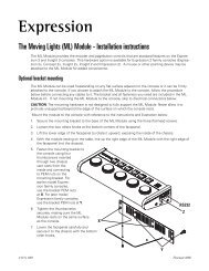
The <strong>Rotating</strong> <strong>Wheel</strong> <strong>Module</strong> contains a wheel with three rotating/indexing positions for<br />
static M-size steel or glass gobos or dichroic color filters and an open position.<br />
Install a gobo/filter:<br />
Step 1: If module is currently installed:<br />
a: Power-down the fixture by moving the power switch to the “off” position.<br />
b: Remove the module from the fixture by loosening the two retaining screws and<br />
pulling the module straight out of the head.<br />
CAUTION: Screws securing the modules, and the wheels themselves, may be hot if the fixture<br />
has recently been lit. Allow the module to cool before installing gobos or filters.<br />
1<br />
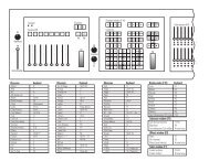
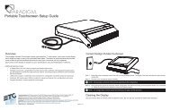
Step 2: Remove the spring securing the gobo/filter you want to replace or install. Use the<br />
diagram below to determine the frame numbers on the wheel. The <strong>Rotating</strong><br />
<strong>Wheel</strong> <strong>Module</strong> has two magnets, one for calibrating the wheel position, and one<br />
for calibrating the index position of the frames (found in the alignment hole of<br />
frame #3).<br />
Open<br />
(0)<br />
2<br />
3<br />
<strong>Rotating</strong> <strong>Wheel</strong> <strong>Module</strong><br />
Magnets<br />
Detail: gobo installed<br />
Alignment Hole<br />
M-Size Gobo<br />
Americas � 3031 Pleasant View Road, P.O. Box 620979, Middleton, Wisconsin 53562-0979 USA � Tel: +1 608 831 4116 � 800 688 4116 � Fax: +1 608 836 1736 � 800 555 8912<br />
Europe � Unit 5, Victoria Industrial Estate, Victoria Road, London W3 6UU, UK � Tel: +44 (0)20 8896 1000 � Fax: +44 (0)20 8896 2000<br />
Asia � Room 605-606, Tower III Enterprise Square, 9 Sheung Yuet Road, Kowloon Bay, Kowloon, Hong Kong � Tel: +852 2799 1220 � Fax: +852 2799 9325<br />
Web: www.etcconnect.com � Email: (US) mail@etcconnect.com � (UK) mail@etceurope.com � (Asia) mail@etcasia.com<br />
Service: service@etcconnect.com � Toll free: 800 775 4382 � Comments about this document: techcomm@etcconnect.com<br />
7160M1330 � Rev A � Released 02/2004 � Copyright © 2004 Electronic Theatre Controls, Inc. All Rights Reserved. Product information and specifications subject to change.<br />
<strong>Rotating</strong> <strong>Wheel</strong> <strong>Module</strong> Quick Guide Page 1 of 2 Electronic Theatre Controls, Inc.<br />
Spring
Quick Guide:<br />
Source Four ® Revolution <strong>Rotating</strong> <strong>Wheel</strong> <strong>Module</strong><br />
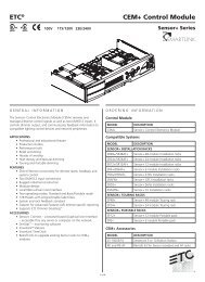
Step 3: Remove the gobo/filter, if present.<br />
Step 4: Insert the new gobo/filter in the frame. Use the hole in or near the frame (see<br />
above for alignment hole locations) to align your gobo, if required.<br />
CAUTION: To prevent cracking of glass gobos and for best image contrast, the silver reflective<br />
surface of the gobo must face the lamp and the black surface of the gobo must face<br />
the lenses. Prolonged use of the <strong>Rotating</strong> <strong>Wheel</strong> <strong>Module</strong> in Bay #2 may cause the<br />
belt within the module to degrade. To ensure peak performance of the RWM, use<br />
it in Bay #1.<br />
Step 5: Insert the spring into the frame. Ensure that the gobo/filter is held securely in<br />
place and that the spring is fully inserted in the frame.<br />
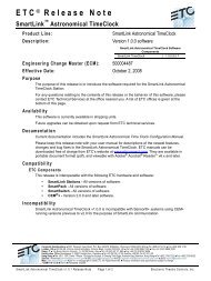
Step 6: Align the module in the selected bay with the interface connector closest to the<br />
center bay divider.<br />
Step 7: Guide the module gently into the bay making certain that the guide posts of the<br />
module housing are properly aligned with the accommodating hole in the fixture<br />
frame. Ensure that the module seats on the control card.<br />
Step 8: Tighten the screws securing the module by turning them to the right (clockwise).<br />
Ensure that the screws are tightened completely.<br />
Bay #1<br />
Bay #2<br />
<strong>Rotating</strong> <strong>Wheel</strong> <strong>Module</strong> Quick Guide Page 2 of 2 Electronic Theatre Controls, Inc.