Legacy Unison Contact Interface Quick Guide - ETC
Legacy Unison Contact Interface Quick Guide - ETC
Legacy Unison Contact Interface Quick Guide - ETC

Create successful ePaper yourself
Turn your PDF publications into a flip-book with our unique Google optimized e-Paper software.
<strong>Unison</strong> <strong>Contact</strong> <strong>Interface</strong> <strong>Quick</strong> <strong>Guide</strong><br />
��<br />
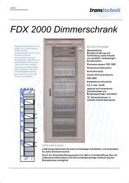
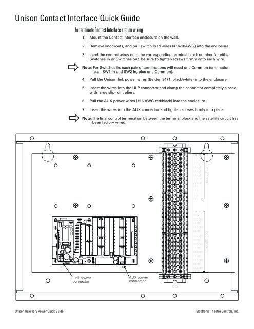
To terminate <strong>Contact</strong> <strong>Interface</strong> station wiring<br />
Link power<br />
connector<br />
1. Mount the <strong>Contact</strong> <strong>Interface</strong> enclosure on the wall.<br />
2. Remove knockouts, and pull switch load wires (#16-18AWG) into the enclosure.<br />
3. Land the control wires onto the corresponding terminal block number for either<br />
Switches In or Switches out. Be sure to tighten screws firmly onto each wire.<br />
Note: For Switches In, each pair of terminations will need one Common termination<br />
(e.g., SW1 In and SW2 In, plus one Common).<br />
4. Pull the <strong>Unison</strong> link power wires (Belden 8471; black/white) into the enclosure.<br />
5. Insert the wires into the ULP connector and clamp the connector completely closed<br />
with large slip-joint pliers.<br />
6. Pull the AUX power wires (#16 AWG red/black) into the enclosure.<br />
7. Insert the wires into the AUX connector and tighten screws firmly into place.<br />
Note: The final control termination between the terminal block and the satellite circuit has<br />
been factory wired.<br />
��<br />
AUX power<br />
connector<br />
<strong>Unison</strong> Auxilliary Power <strong>Quick</strong> <strong>Guide</strong> Electronic Theatre Controls, Inc.<br />
���<br />
��� ��<br />
��� ��<br />
��� ��<br />
��� ��<br />
��� ��<br />
��� ��<br />
��� ��<br />
��� ��<br />
���<br />
���<br />
���<br />
���<br />
��� ���<br />
����<br />
��� ���<br />
����<br />
��� ���<br />
����<br />
��� ���<br />
����<br />
��� ���<br />
����<br />
��� ���<br />
����<br />
��� ���<br />
����<br />
��� ���<br />
����<br />
������ ��<br />
������ ���
��<br />
To terminate Fader <strong>Interface</strong> station wiring<br />
1. Mount the Fader <strong>Interface</strong> enclosure on the wall.<br />
2. Remove knockouts, and pull fader and lamp load wires (#16-18AWG) into the<br />
enclosure.<br />
3. Land the control wires onto the corresponding fader terminal. Be sure to tighten<br />
screws firmly onto each wire.<br />
4. If you have an indicator lamp for each potentiometer, land those control wires onto<br />
the corresponding lamp terminal.<br />
5. Terminate the Com and +5Vdc wires.<br />
6. Pull the <strong>Unison</strong> link power wires (Beldon 8471; black/white) into the enclosure.<br />
7. Insert the wires into the ULP connector and clamp the connector completely closed<br />
with large slip-joint pliers.<br />
8. Pull the AUX power wires (#16 AWG red/black) into the enclosure.<br />
9. Insert the wires into the AUX connector and tighten screws firmly into place.<br />
Note: The final control termination between the terminal block and the satellite circuit has<br />
been factory wired.<br />
Link power<br />
connector<br />
��<br />
AUX power<br />
connector<br />
Part#: 7081M1021 Rev. B 10/2007<br />
���<br />
���<br />
���<br />
���<br />
���<br />
���<br />
���<br />
���<br />
���<br />
�����<br />
���<br />
���<br />
���<br />
���<br />
���<br />
���<br />
���<br />
���<br />
���<br />
���<br />
����� �����