N122-001 Series Servoamplifier with Oscillator ... - Moog Inc
N122-001 Series Servoamplifier with Oscillator ... - Moog Inc
N122-001 Series Servoamplifier with Oscillator ... - Moog Inc

You also want an ePaper? Increase the reach of your titles
YUMPU automatically turns print PDFs into web optimized ePapers that Google loves.
<strong>N122</strong>-<strong>001</strong> <strong>Series</strong><br />
<strong>Servoamplifier</strong> <strong>with</strong><br />
<strong>Oscillator</strong>/Demodulator<br />
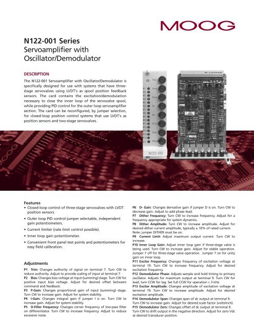
DESCRIPTION<br />
The <strong>N122</strong>-<strong>001</strong> <strong>Servoamplifier</strong> <strong>with</strong> <strong>Oscillator</strong>/Demodulator is<br />
specifically designed for use <strong>with</strong> systems that have threestage<br />
servovalves using LVDT's as spool position feedback<br />
sensors. The card contains the excitation/demodulation<br />
necessary to close the inner loop of the servovalve spool,<br />
while providing PID control for the outer loop servoamplifier<br />
section. The card can be reconfigured, by jumper selection,<br />
for closed-loop position control systems that use LVDT's as<br />
position sensors and two-stage servovalves.<br />
Features<br />
• Closed-loop control of three-stage servovalves <strong>with</strong> LVDT<br />
position sensors.<br />
• Outer loop PID control-jumper selectable, independent<br />
gain potentiometers.<br />
• Current limiter (rate limit control possible).<br />
• Inner loop gain potentiometer.<br />
• Convenient front panel test points and potentiometers for<br />
easy field calibration.<br />
Adjustments<br />
P1 Trim: Changes authority of signal on terminal 7. Turn CW to<br />
reduce authority. Adjust to provide scaling of input at terminal 7.<br />
P2 Bias: Changes bias voltage at input (summing) stage. Turn CW for<br />
positive input bias voltage. Adjust for desired offset between<br />
command and feedback.<br />
P3 P-Gain: Changes proportional gain of input (summing) stage.<br />
Turn CW to increase gain. Adjust for system stability.<br />
P4 I-Gain: Changes integral gain if jumper I is on. Turn CW to<br />
increase gain. Adjust for system stability.<br />
P5 D-Filter Frequency: Changes corner frequency of low-pass filter<br />
on differentiator. Turn CW to increase frequency. Adjust to reduce<br />
excessive noise.<br />
P6 D- Gain: Changes derivative gain if jumper D is on. Turn CW to<br />
decrease gain. Adjust to add phase lead.<br />
P7 Dither Frequency: Turn CW to increase frequency. Adjust for a<br />
frequency appropriate for system dynamics.<br />
P8 Dither Amplitude: Turn CW to increase amplitude. Adjust for<br />
desired dither current amplitude, typically ± 10% of rated current.<br />
Note: jumper DITHER must be on.<br />
P9 Current Limit: Adjust maximum output current. Turn CW to<br />
increase.<br />
P10 Inner Loop Gain: Adjust inner loop gain if three-stage valve is<br />
being used. Turn CW to increase gain. Adjust for stable operation.<br />
Jumper 7 off for three-stage valve operation. Jumper 7 on for unity<br />
gain on inner loop.<br />
P11 Exciter Frequency: Changes frequency of excitation voltage at<br />
terminal 19. Turn CW to increase frequency. Adjust for desired<br />
excitation frequency.<br />
P12 Demodulator Phase: Adjusts sample and hold timing to primary<br />
oscillator. Adjusts for maximum output at terminal 9. Turn CW for<br />
lead, turn CCW for lag. Set full CCW for operation ≤ 3 kHz.<br />
P13 Exciter Amplitude: Changes amplitude of excitation voltage at<br />
terminal 19. Turn CW to increase amplitude. Adjust for desired<br />
excitation amplitude.<br />
P14 Demodulator Span: Changes span of dc output at terminal 9.<br />
Turn CW to increase gain. Adjust for desired scale factor (volts/inch).<br />
P15 Demodulator Zero: Changes offset of dc output at terminal 9.<br />
Turn CW to shift output in the negative direction. Adjust for zero Vdc<br />
at desired transducer position.
TECHNICAL DATA<br />
N-<br />
SPECIFICATIONS<br />
<strong>Servoamplifier</strong><br />
Servovalve Drive: ± 100 mA into 100Ω<br />
Proportional Gain: 5 to 300 mA/V<br />
Integral Gain: 8 to 4000 mA/V-sec<br />
Differential Gain: 0.04 to 4 mA-sec/V<br />
Inner Loop Gain: 10 to 200 mA/V<br />
Exciter<br />
Frequency:<br />
Amplitude:<br />
Stability:<br />
100 to 2500 Hz<br />
2 to 11 Vpp<br />
≤ 250 ppm amplitude/°C<br />
Demodulator<br />
Ripple:<br />
Linearity:<br />
Stability:<br />
Gain:<br />
Frequency<br />
Response:<br />
Temperature<br />
Range:<br />
Form Factor:<br />
Weight:<br />
< 40 mV p-p at the excitation frequency<br />
≤ ± 0.2% at 1.2 kHz<br />
± 250 ppm gain/°C; ± 0.01 mV/°C<br />
1 to 10 Vdc/V p-p typical, varies <strong>with</strong><br />
transducer characteristics<br />
Linear from 0 to 180° as a function of<br />
excitation frequency<br />
0°C to 50°C (32°F to 122°F)<br />
Eurocard 100 x 160 mm, 7HP, 3 U<br />
0.5 lb.<br />
SCHEMATIC<br />
Notes:<br />
P ... P3 GAIN ADJ JMPR1 ON/OFF<br />
I ... P4 GAIN ADJ JMPR2 ON/OFF<br />
D ... P6 GAIN ADJ JMPR3 ON/OFF<br />
... P5 FILTER ADJ<br />
INNER LOOP<br />
GAIN ADJUST<br />
P10<br />
CURRENT<br />
LIMITER<br />
P9 ADJUSTMENT<br />
1. Indicates test<br />
points located on front<br />
panel.<br />
2. CAUTION: Perform<br />
adjustments <strong>with</strong><br />
hydraulic system off.<br />
Before applying power<br />
to any cards, disconnect<br />
the servovalves. They<br />
should not be connected<br />
until current limit has<br />
been set.<br />
3. An “extender card”<br />
is highly recommended<br />
to gain access to test<br />
points and adjustments<br />
while cards are<br />
powered-up <strong>with</strong>in a<br />
eurocard rack assembly.<br />
(<strong>Moog</strong> ref P/N A81750-1)<br />
4 Operating points on<br />
ends of ‘LVDT” coils will<br />
become increasingly<br />
non-linear and should<br />
be avoided. An<br />
operating range over<br />
the ± span of the LVDT<br />
core adjustment must be<br />
made to achieve<br />
optimum linear<br />
performance results.<br />
PCB TEST POINT<br />
TP1<br />
TP2<br />
TP3<br />
TP4<br />
TP5<br />
FRONT PANEL<br />
VIN1<br />
VIN2<br />
VIN3<br />
VP<br />
ISV<br />
FEEDBACK<br />
COMMAND<br />
INNER LOOP<br />
FEEDBACK<br />
NC<br />
NO<br />
COMMON<br />
ACTIVE LOW<br />
ACTIVE HIGH<br />
BUFFERED<br />
DEMODULATED<br />
OUTPUT<br />
DEMODULATOR<br />
OUTPUT<br />
VIN1 VIN2<br />
1<br />
P1<br />
2<br />
-<br />
COMMAND TRIM<br />
3<br />
+<br />
4<br />
12<br />
13<br />
14<br />
15<br />
16<br />
8<br />
9<br />
JUMPER<br />
MUST BE<br />
CONNECTED<br />
VIN3<br />
-<br />
+24 V<br />
BUFFER<br />
DIFFERENCE<br />
AMPLIFIER<br />
P2<br />
SYSTEM BIAS<br />
K1<br />
RELAY<br />
K1<br />
(RED LED)<br />
20<br />
24<br />
26<br />
29<br />
28<br />
VDEM<br />
P<br />
I<br />
D<br />
OSCILLATOR<br />
P11 FREQUENCY ADJ<br />
P13 AMPLITUDE ADJ<br />
SAMPLING PULSE<br />
P12 PHASE ADJ<br />
DEMODULATOR<br />
P14 SPAN ADJ<br />
P15 ZERO ADJ<br />
+24V @ 15 mA<br />
POWER GROUND<br />
-24V @ SERVOVALVE CURRENT<br />
+15VREF @ 70 mA<br />
+15V @ 70 mA<br />
JMPR7<br />
INNER LOOP<br />
SUM & GAIN<br />
P10<br />
DITHER<br />
P7 FREQUENCY<br />
P8 AMPLITUDE<br />
JMPR4 ON/OFF<br />
CURRENT<br />
OR VOLTAGE<br />
JUMPERS<br />
19<br />
21<br />
P12 FULL CCW FOR OPERATION < 3 KHZ<br />
VSEC<br />
VOSC<br />
17<br />
18<br />
4<br />
ISV<br />
6<br />
7<br />
LVDT<br />
SERVOVALVE<br />
TJWhite / Register / 250<br />
<strong>Moog</strong> is a registered trademark of <strong>Moog</strong> <strong>Inc</strong>. and its subsidiaries. All trademarks as indicated herein are the<br />
property of <strong>Moog</strong> <strong>Inc</strong>. and its subsidiaries. ©<strong>Moog</strong> <strong>Inc</strong>. 2003. All rights reserved. All changes are reserved.<br />
TP6<br />
VOSC<br />
22<br />
SIGNAL GROUND<br />
TP7<br />
TP8<br />
VSEC<br />
VDEM<br />
30<br />
31<br />
-15V @ 70 mA<br />
-15VREF @ 70 mA<br />
© <strong>Moog</strong> <strong>Inc</strong>., Industrial Controls Division • USA: +1-716-655-3000 • Germany: +49-7031-622-0 • Japan: +81-463-55-3615<br />
For the location nearest you, contact www.moog.com/worldwide. For complete disclaimers, see www.moog.com/disclaimers<br />
<strong>N122</strong>-<strong>001</strong> <strong>Servoamplifier</strong> CDL6187 RevD 500-217 02/04