AS-80/AS-90 Scorers w/LED Overheads - Brunswick
AS-80/AS-90 Scorers w/LED Overheads - Brunswick
AS-80/AS-90 Scorers w/LED Overheads - Brunswick

Create successful ePaper yourself
Turn your PDF publications into a flip-book with our unique Google optimized e-Paper software.
Pre-Installation/Installation Manual<br />
<strong>AS</strong>-<strong>80</strong>/<strong>AS</strong>-<strong>90</strong> <strong>Scorers</strong><br />
w/<strong>LED</strong> <strong>Overheads</strong><br />
October 2013 / 57-<strong>90</strong>0714-000
<strong>AS</strong>-<strong>80</strong>/<strong>90</strong> <strong>Scorers</strong> w/<strong>LED</strong> <strong>Overheads</strong> Pre-Installation/Installation Manual<br />
© October 2013 by the <strong>Brunswick</strong> Bowling and Billiards Corporation. All rights reserved.<br />
<strong>AS</strong>-<strong>90</strong> and <strong>AS</strong>-<strong>80</strong> are registered trademarks of the <strong>Brunswick</strong> Bowling and Billiards Corporation.<br />
Reorder Part No. 57-<strong>90</strong>0714-000<br />
Notice: If available, updates to this manual can be found on-line at www.brunswickbowling.com.<br />
Confidential proprietary information. All information contained in this document is subject to change<br />
without notice.<br />
<strong>Brunswick</strong> Bowling & Billiards Corporation<br />
525 West Laketon Avenue<br />
P.O. Box 329<br />
Muskegon, MI 49443-0329<br />
U.S.A.<br />
231.725.3300<br />
2 <strong>AS</strong>-<strong>80</strong>/<strong>90</strong> w/<strong>LED</strong> Overhead Monitors Pre-Installation/Installation Manual
Notes & Warnings<br />
SAFETY!<br />
Throughout this publication, “Warnings”, and “Cautions” (accompanied by one of the International<br />
HAZARD Symbols) are used to alert the mechanic to special instructions concerning a particular<br />
service or operation that may be hazardous if performed incorrectly or carelessly. They are defined<br />
below. OBSERVE AND READ THEM CAREFULLY!<br />
These “Safety Alerts” alone cannot eliminate the hazards that they signal. Strict compliance to these<br />
special instructions when performing the service, plus training and “Common Sense” operation are<br />
major accident prevention measures.<br />
NOTE or IMPORTANT!: Will designate significant informational notes.<br />
WARNING! Will designate a mechanical or nonelectrical alert which could<br />
potentially cause personal injury or death.<br />
WARNING! Will designate electrical alerts which could potentially cause<br />
personal injury or death.<br />
CAUTION! Will designate an alert which could potentially cause product<br />
damage.<br />
Will designate grounding alerts.<br />
<strong>AS</strong>-<strong>80</strong>/<strong>90</strong> w/<strong>LED</strong> Overhead Monitors Pre-Installation/Installation Manual 3
Safety Notice to Users of this Manual<br />
This manual has been written and published by the Service Department of <strong>Brunswick</strong> Bowling and<br />
Billiards to aid the reader when servicing or installing the products described.<br />
It is assumed that these personnel are familiar with, and have been trained in, the servicing or<br />
installation procedures of these products, which includes the use of common mechanic’s hand tools and<br />
any special <strong>Brunswick</strong> or recommended tools from other suppliers.<br />
We could not possibly know of and advise the reader of all conceivable procedures by which a service<br />
might be performed and of the possible hazards and/or results of each method. We have not attempted<br />
any such wide evaluation. Therefore, anyone who uses a service procedure and/or tool, which is not<br />
recommended by <strong>Brunswick</strong>, must first completely satisfy himself that neither his nor the product’s<br />
safety will be endangered by the service procedure selected.<br />
All information, illustrations and specifications contained in this manual are based on the latest product<br />
information available at the time of publication.<br />
It should be kept in mind, while working on the product, that the electrical system is capable of violent<br />
and damaging short circuits or severe electrical shocks. When performing any work where electrical<br />
terminals could possibly be grounded or touched by the mechanic, the power to the product should be<br />
disconnected prior to servicing and remain disconnected until servicing is complete.<br />
4 <strong>AS</strong>-<strong>80</strong>/<strong>90</strong> w/<strong>LED</strong> Overhead Monitors Pre-Installation/Installation Manual
Contents<br />
Packaging..................................................................................................................................6<br />
Pre-Installation Requirements................................................................................................7<br />
Removing <strong>AS</strong>-<strong>80</strong>/<strong>90</strong> overhead monitors.............................................................................. 7<br />
Site Survey........................................................................................................................... 7<br />
<strong>AS</strong>-<strong>80</strong>/<strong>90</strong> Interface............................................................................................................... 8<br />
32” <strong>LED</strong> monitor w/<strong>AS</strong>-<strong>80</strong>/<strong>90</strong> <strong>LED</strong> interface..................................................................... 9<br />
All Scoring Systems....................................................................................................................................... 9<br />
40” <strong>LED</strong> Monitor with <strong>AS</strong>-<strong>80</strong>/<strong>90</strong> <strong>LED</strong> Interface................................................................. 9<br />
All Scoring Systems....................................................................................................................................... 9<br />
46” <strong>LED</strong> Monitor with <strong>AS</strong>-<strong>80</strong>/<strong>90</strong> <strong>LED</strong> Interface................................................................. 9<br />
All Scoring Systems....................................................................................................................................... 9<br />
Installation Instructions.........................................................................................................10<br />
Overviews.......................................................................................................................... 10<br />
Command Network ........................................................................................................... 10<br />
Color Vision w/Color Control Box.............................................................................................................. 11<br />
Color Vision w/Color Console..................................................................................................................... 12<br />
Removing <strong>AS</strong><strong>80</strong>/<strong>90</strong> Overhead Monitors............................................................................ 13<br />
External Connections................................................................................................................................... 14<br />
Power........................................................................................................................................................... 15<br />
Internal Connections.................................................................................................................................... 16<br />
Switch Settings............................................................................................................................................ 18<br />
Jumper................................................................................................................................ 20<br />
Scorer Console Power Supply............................................................................................ 20<br />
12VDC Power Supply (57-214156-<strong>80</strong>0)..................................................................................................... 20<br />
5VDC Power Supply (All Models).............................................................................................................. 21<br />
Initial Set-Up................................................................................................................................................ 21<br />
Current Output Adjustments........................................................................................................................ 22<br />
Voltage Output Adjustment.......................................................................................................................... 22<br />
CRT Driver PCB................................................................................................................ 25<br />
13” Color CRT Assembly (<strong>AS</strong>-K Model).......................................................................... 26<br />
Video Processor PCB......................................................................................................... 27<br />
Color Decode PCB............................................................................................................. 28<br />
Forms and Character Adjustment................................................................................................................. 29<br />
Power-Up........................................................................................................................... 29<br />
<strong>LED</strong> Adjustments............................................................................................................... 30<br />
For Image Size and Position........................................................................................................................ 30<br />
To Turn on Dynamic Contrast...................................................................................................................... 30<br />
Calibration.......................................................................................................................... 31<br />
Trouble Shooting.....................................................................................................................32<br />
Monochrome................................................................................................................................................ 33<br />
ColorVision.................................................................................................................................................. 33<br />
Source Command and Command Network................................................................................................. 34<br />
RS 232 Communication............................................................................................................................... 35<br />
Service Light................................................................................................................................................ 36<br />
Heartbeat...................................................................................................................................................... 36<br />
Color Comline.............................................................................................................................................. 36<br />
<strong>LED</strong> Menu Display...................................................................................................................................... 36<br />
Cables.......................................................................................................................................39<br />
<strong>AS</strong>-<strong>80</strong>/<strong>90</strong> w/<strong>LED</strong> Overhead Monitors Pre-Installation/Installation Manual 5
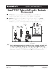
Packaging<br />
Page 1 of 1<br />
Model NUMBer coNfigUratioN<br />
BRUNSWICK BOWLING & BILLIARDS CORPORATION<br />
Drawing Number: e3-300439-000 Rev. No: h<br />
descriPtioN: MNc - as<strong>80</strong>/<strong>90</strong> lcd video iNterface<br />
rev. Qty. Part NUMBer<br />
descriPtioN of Package<br />
2.00* 11-697009-000 tERMINAtoR - 75 oHM, f CoNNECtoR<br />
1.00 57-501029-000 <strong>AS</strong>S'Y. - CABLE, <strong>AS</strong><strong>80</strong>/<strong>90</strong> CoLoR CoMLINE "Y"<br />
1.00 57-861288-000 PkG. - LINE CoRD, 7 1/2' LoNG<br />
1.00 57-863379-403 PkG. - <strong>AS</strong><strong>80</strong>/<strong>90</strong> LCD VIDEo INtERfACE<br />
1.00 57-863536-000 PkG. - CABLE, SERIAL, f-f, 1:1, BLACk, 6'<br />
1.00 57-863537-000 PkG. - <strong>AS</strong><strong>80</strong>/<strong>90</strong> LCD INtERfACE HARDWARE<br />
1.00 57-863538-000 PkG. - CABLE, PoWER, IEC JUMPER, 6'<br />
1.00 57-863539-000 PkG. - CABLE, VIDEo, RCA CoNNECtoR, BLACk, 6'<br />
0.50 57-863540-000 PkG. - CABLE, VIDEo, CoAx, f CoNNECtoR, BLACk, 6'<br />
1.00* 57-<strong>90</strong>0714-000 INStALLAtIoN MANUAL<br />
*PER CENtER<br />
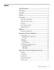
Page 1 of 1<br />
Model NUMBer coNfigUratioN<br />
BRUNSWICK BOWLING & BILLIARDS CORPORATION<br />
Drawing Number: e3-300440-000 Rev. No: d<br />
descriPtioN: MNc - as<strong>80</strong>/<strong>90</strong> lcd video iNterface sPare Parts kit<br />
rev. Qty. Part NUMBer<br />
descriPtioN of Package<br />
1.00 57-863049-000 PkG. - SPARE fUSE kIt, 5 AMP, 5x20 MM<br />
1.00 57-863265-000 PkG. - tRIPLE oUtPUt PoWER SUPPLY<br />
1.00 57-500921-403 <strong>AS</strong>SY - PRoGRAMMED <strong>AS</strong><strong>80</strong>/<strong>90</strong> LCD INtERfACE BoARD<br />
1.00 11-697009-000 tERMINAtoR - 75 oHM, f CoNNECtoR<br />
1.00 57-5008<strong>80</strong>-000 <strong>AS</strong>SY. - CALIBRAtIoN PUSHBUttoN AND <strong>LED</strong><br />
6 <strong>AS</strong>-<strong>80</strong>/<strong>90</strong> w/<strong>LED</strong> Overhead Monitors Pre-Installation/Installation Manual
Pre-Installation Requirements<br />
Removing <strong>AS</strong>-<strong>80</strong>/<strong>90</strong> overhead monitors<br />
CAUTION! When removing existing overhead monitors, it will be necessary to<br />
open the enclosure and carefully disconnect the existing cables. DO NOT CUT<br />
any of the existing cables. All Cables from the ceiling will be reused.<br />
Site Survey<br />
1. The <strong>LED</strong> overheads require different electrical requirements than the old CRT overheads.<br />
Please review the information below with the customer to inform them of their additional<br />
electrical responsibilities.<br />
a. Isolated Ground (IG) outlet is required for the <strong>LED</strong> Overhead.<br />
b.<br />
<strong>LED</strong> Lane Pair with<br />
Interface Electronics<br />
Total Amperage Per Lane Pair<br />
Overhead (120/230 Volt)<br />
32” <strong>LED</strong> 2.9/1.45<br />
40” <strong>LED</strong> 2.9/1.45<br />
46” <strong>LED</strong> 2.9/1.45<br />
55” <strong>LED</strong> 4.3/2.15<br />
2. What is the ceiling height, from the lane surface over the approach area where monitors will be<br />
located? _______<br />
a. For 32” <strong>LED</strong> we recommend 10’-6” (3200 mm) ceiling heights, minimum of<br />
9’-6” (2896 mm).<br />
b. For 40” <strong>LED</strong> we recommend 10’-10” (3302 mm) ceiling heights, minimum of<br />
9’-10” (2997 mm ).<br />
c. For 46” <strong>LED</strong> we recommend 11’-1” (3378 mm) ceiling heights, minimum of 10’-1”<br />
(3073 mm).<br />
5. For 55” <strong>LED</strong> we recommend 11’-3” (3429 mm) ceiling heights, minimum of 10’-4”<br />
(3150 mm).<br />
NOTE: The <strong>LED</strong> monitor may be installed with ceilings lower than the minimum ceiling height<br />
distance, but the customer should be aware the height from the lane to the bottom of the monitor<br />
would be less than 89.”<br />
IMPORTANT!: The site survey and overhead certificate must be completed and sent to<br />
Contract Management before the contract can be approved and shipped.<br />
<strong>AS</strong>-<strong>80</strong>/<strong>90</strong> w/<strong>LED</strong> Overhead Monitors Pre-Installation/Installation Manual 7
<strong>AS</strong>-<strong>80</strong>/<strong>90</strong> Interface<br />
Volts Hertz AC/DC Phase AMPS<br />
Per Unit<br />
Electrical Information<br />
Watts<br />
Branch<br />
Circuit<br />
Customer<br />
Responsibility<br />
100-130<br />
200-240<br />
50/60 AC 1 0.5@120V<br />
0.25@240V<br />
60 2 Wires +<br />
Isolated<br />
Ground<br />
8 <strong>AS</strong>-<strong>80</strong>/<strong>90</strong> w/<strong>LED</strong> Overhead Monitors Pre-Installation/Installation Manual
32” <strong>LED</strong> monitor LANE PAIR with <strong>AS</strong>-<strong>80</strong>/<strong>90</strong> <strong>LED</strong> interface<br />
All Scoring Systems<br />
Volts Hertz AC/DC Phase AMPS<br />
Per Unit<br />
Electrical Information<br />
Watts<br />
Branch<br />
Circuit<br />
Customer Responsibility<br />
100-130 50/50 AC 1 2.9@<br />
120V<br />
94<br />
2 Wires +<br />
Isolated<br />
Ground<br />
Install circuit with 120 Volt Hubbell I.G.<br />
5262 Receptacle or Equivalent<br />
No more than 8 <strong>LED</strong> overheads<br />
per 20amp circuit<br />
200-240 50/50 A/C 1 1.45 @<br />
240V<br />
94<br />
2 Wires +<br />
Isolated<br />
Ground<br />
Install circuit with 120 Volt Hubbell I.G.<br />
5262 Receptacle or Equivalent<br />
No more than 14 <strong>LED</strong> overheads<br />
per 16amp circuit<br />
40” <strong>LED</strong> Monitor LANE PAIR with <strong>AS</strong>-<strong>80</strong>/<strong>90</strong> <strong>LED</strong> Interface<br />
All Scoring Systems<br />
Volts Hertz AC/DC Phase AMPS<br />
Per Unit<br />
100-130 50/60 AC 1 2.9@<br />
120V<br />
Electrical Information<br />
Watts<br />
119<br />
Branch<br />
Circuit<br />
2 Wires +<br />
Isolated<br />
Ground<br />
Customer Responsibility<br />
Install circuit with 120 Volt Hubbell I.G.<br />
5262 Receptacle or Equivalent<br />
No more than 8 <strong>LED</strong> overheads<br />
per 20 amp circuit<br />
200-240 50/60 A/C 1 1.45 @<br />
240V<br />
119<br />
2 Wires +<br />
Isolated<br />
Ground<br />
Install Hubbell I.G. Receptacle or<br />
Equivalent No more than 8 <strong>LED</strong><br />
overheads per 14 amp circuit<br />
46” <strong>LED</strong> Monitor LANE Pair with <strong>AS</strong>-<strong>80</strong>/<strong>90</strong> <strong>LED</strong> Interface<br />
All Scoring Systems<br />
Volts Hertz AC/DC Phase AMPS<br />
Per Unit<br />
100-130 50/60 AC 1 2.9 @<br />
120V<br />
Electrical Information<br />
Watts<br />
136<br />
Branch<br />
Circuit<br />
2 Wires +<br />
Isolated<br />
Ground<br />
Customer Responsibility<br />
Install circuit with 120 Volt Hubbell I.G.<br />
5262 Receptacle or Equivalent<br />
No more than 8 <strong>LED</strong> overheads<br />
per 20amp circuit<br />
200-240 50/60 A/C 1 1.45 @<br />
240V<br />
136<br />
2 Wires +<br />
Isolated<br />
Ground<br />
Install Hubbell I.G. Receptacle or<br />
Equivalent No more than 14 <strong>LED</strong><br />
overheads per 16amp circuit<br />
<strong>AS</strong>-<strong>80</strong>/<strong>90</strong> w/<strong>LED</strong> Overhead Monitors Pre-Installation/Installation Manual 9
55” <strong>LED</strong> Monitor LANE Pair with <strong>AS</strong>-<strong>80</strong>/<strong>90</strong> <strong>LED</strong> Interface<br />
All Scoring Systems<br />
Volts Hertz AC/DC Phase AMPS<br />
Per Unit<br />
100-130 50/60 AC 1 4.3 @<br />
120V<br />
Electrical Information<br />
Watts<br />
164<br />
Branch<br />
Circuit<br />
2 Wires +<br />
Isolated<br />
Ground<br />
Customer Responsibility<br />
Install circuit with 120 Volt Hubbell I.G.<br />
5262 Receptacle or Equivalent<br />
No more than 6 <strong>LED</strong> overheads<br />
per 20amp circuit<br />
200-240 50/60 A/C 1 2.15 @<br />
240V<br />
164<br />
2 Wires +<br />
Isolated<br />
Ground<br />
Install Hubbell I.G. Receptacle or<br />
Equivalent No more than 10 <strong>LED</strong><br />
overheads per 16amp circuit<br />
10 <strong>AS</strong>-<strong>80</strong>/<strong>90</strong> w/<strong>LED</strong> Overhead Monitors Pre-Installation/Installation Manual
Overviews<br />
Command Network<br />
Installation Instructions<br />
Figure 1. Command Network Overview<br />
<strong>AS</strong>-<strong>80</strong>/<strong>90</strong> w/<strong>LED</strong> Overhead Monitors Pre-Installation/Installation Manual 11
Color Vision w/Color Control Box<br />
Figure 2. Color Vision Interconnection with Color Control Box<br />
12 <strong>AS</strong>-<strong>80</strong>/<strong>90</strong> w/<strong>LED</strong> Overhead Monitors Pre-Installation/Installation Manual
Color Vision w/Color Console<br />
Figure 3. Color Vision w/Color Console Overview<br />
<strong>AS</strong>-<strong>80</strong>/<strong>90</strong> w/<strong>LED</strong> Overhead Monitors Pre-Installation/Installation Manual 13
Removing <strong>AS</strong><strong>80</strong>/<strong>90</strong> Overhead Monitors<br />
CAUTION! When removing existing overhead monitors, it will be necessary<br />
to open the enclosure and carefully disconnect the existing cables. DO NOT<br />
CUT any of the existing cables. All cables which come from the ceiling will<br />
be reused in the new installation. The only exception is for the color comline<br />
cable which connects the two enclosure circuit boards to the cable which<br />
comes out of the ceiling. This cable is either daisy chained to the two boards<br />
or “Y” connected to the two boards. Disconnect this cable from the ceiling<br />
cable (below the level of the ceiling) and discard.<br />
<strong>AS</strong>-<strong>80</strong>/<strong>90</strong> Interface<br />
Mount the <strong>LED</strong> Interface box to the overhead <strong>LED</strong> mounting structure.<br />
1. Slide clamp over tube of <strong>LED</strong> support weldment.<br />
Figure 4. Mount Interface<br />
2. Use 1/4-20 x 1” pan head screw and 1/4” keps nuts to secure the interface box and clamp to<br />
overhead weldment, ensuring there is clearance between the cables and the overhead weldment.<br />
14 <strong>AS</strong>-<strong>80</strong>/<strong>90</strong> w/<strong>LED</strong> Overhead Monitors Pre-Installation/Installation Manual
External Connections<br />
MONOCHROME INSTALLATION<br />
Install the terminator on each overhead.<br />
1. Install a 75 ohm terminator on any one of the ”global TV video IN/OUT”, J1 or J2 connectors<br />
for each overhead. Refer to Figure 5.<br />
Figure 5. Install Terminator<br />
COLOR VISION INSTALLATION<br />
Install the global video daisy chain cables.<br />
1. Connect the global video daisy chain cables to ”global TV video IN/OUT” (J1-J2 or J3-J4)<br />
NOTE: All four connectors are parallel, so directionis not important. “BNC” and “F”<br />
connections may be mixed.<br />
Figure 6. Connect Global Video<br />
2. Install 75 Ohm terminator on last box in global video chassis.<br />
SOURCE COMMAND and COMMAND NETWORK INSTALLATION<br />
A Source Command and a Command Network installation both look the same to an <strong>AS</strong><strong>80</strong>/<strong>90</strong> Interface<br />
Box. Install the global video daisy chain.<br />
1. Connect the global video daisy chain cables to ”global TV video IN/OUT” (J1-J2 or J3-J4)<br />
NOTE: All four connectors are parallel, so directionis not important. “BNC” and “F”<br />
connections may be mixed.<br />
Figure 7. Connect Global Video<br />
2. Install 75 Ohm terminator on last box in global video chassis.<br />
<strong>AS</strong>-<strong>80</strong>/<strong>90</strong> w/<strong>LED</strong> Overhead Monitors Pre-Installation/Installation Manual 15
<strong>LED</strong> INSTALLATION<br />
Install the RCA video cable, VGA cable, and the serial cable to the <strong>LED</strong> overhead from the <strong>AS</strong><strong>80</strong>/<strong>90</strong><br />
interface box.<br />
1. Connect the RCA video cable, VGA cable, and Serial cable to the external connections on the<br />
top of the Interface box and <strong>LED</strong> overhead monitor.<br />
Figure 8. External Connections<br />
Power<br />
Use either the power cord that the <strong>LED</strong> is equipped with or the 7-1/2” power cord, to connect the<br />
interface box to the building power. Discard the unused power cord.<br />
16 <strong>AS</strong>-<strong>80</strong>/<strong>90</strong> w/<strong>LED</strong> Overhead Monitors Pre-Installation/Installation Manual
Internal Connections<br />
Figure 9. Internal Connections<br />
<strong>AS</strong>-<strong>80</strong>/<strong>90</strong> w/<strong>LED</strong> Overhead Monitors Pre-Installation/Installation Manual 17
NOTE: There my or may not be a service lamp for connection to J12 & J13, if there is, connect<br />
cables to odd lane and leave even lane connectors open.<br />
Figure 10.Route Cable to Enclosure<br />
MONOCHROME INSTALLATION<br />
Connect the Service Light cable and the video cable.<br />
1. Connect the video cable to connector J8. Verify that the center conductor of the cable is on<br />
pin #1.<br />
2. Connect the service light from <strong>AS</strong>-<strong>80</strong>/<strong>90</strong> scorer to J12.<br />
3. Connect the service lamp to J13<br />
4. There are NO connections to J9, J10, and J11<br />
COLOR VISION INSTALLATION<br />
Connect the global video, color select input, video select input, and the Service Light.<br />
1. Connect the video selection/video signal input cable (6-pin connector) to connector J9. Verify<br />
that the center contact of the video signal goes to pin #5 of the connector.<br />
2. Connect the color select cable (5-pin connector) to connector J10.<br />
3. Connect the service light cable from <strong>AS</strong>/<strong>80</strong>/<strong>90</strong> cable scorer cable to J12.<br />
4. Connect the service lamp to J13<br />
5. There are NO connections to J8 and J11.<br />
18 <strong>AS</strong>-<strong>80</strong>/<strong>90</strong> w/<strong>LED</strong> Overhead Monitors Pre-Installation/Installation Manual
SOURCE COMMAND and COMMAND NETWORK INSTALLATION<br />
Source Command and Command Network will have the same connection for the <strong>AS</strong><strong>90</strong>/<strong>80</strong> Interface<br />
Box. Connect the global video, global color comline, the video from the Scoring Console, and the<br />
Service Light.<br />
1. Connect the scorer video cable to connector J8.<br />
2. Connect the center connector of the Color Comline “Y” cable assembly (p/n 57-501029-000) to<br />
the Color Comline cable assembly that comes from the ceiling. Connect one of the two ends<br />
of the “Y” cable to connector J11. The other end of the “Y” cable connects to J11 in the other<br />
interface enclosure on the lane pair.<br />
3. Connect the service lamp from <strong>AS</strong>-<strong>80</strong>/<strong>90</strong> cable scorer cable to J12.<br />
4. Connect the service light cable from <strong>AS</strong>-<strong>80</strong>/<strong>90</strong> Scorer to J13<br />
5. There are NO connections to J9 and J10.<br />
Switch Settings<br />
Switch SW1 Setting<br />
(Monochrome Installation)<br />
Bits 1, 2, and 3 of SW1 select one of eight color combinations for the screen. These are the same eight<br />
color combinations that are used in ColorVision, except that they cannot be changed from the Front<br />
Desk. The remaining bits of the switch are not used and can be set to any value.<br />
BITS<br />
Color<br />
1 2 3 4-8 character background forms<br />
OFF OFF OFF Not Used YELLOW LT BLUE WHITE<br />
On OFF Off Not Used YELLOW BLUE WHITE<br />
OFF on OFF Not Used YELLOW GREEN WHITE<br />
On On Off Not Used WHITE YELLOW WHITE<br />
Off OFF On Not Used RED LT GRAY BLACK<br />
ON OFF ON Not Used YELLOW MAGENTA BLACK<br />
Off ON On Not Used BLUE LT YELLOW WHITE<br />
ON ON ON Not Used DO NOT USE<br />
(ColorVision Installation)<br />
Switch SW1 is not used in a ColorVision installation, and may be set to any value.<br />
<strong>AS</strong>-<strong>80</strong>/<strong>90</strong> w/<strong>LED</strong> Overhead Monitors Pre-Installation/Installation Manual 19
(Source Command and Command Network Installation)<br />
For either of the installation types that use a color comline, SW1 is used to set the lane number. Only<br />
bits 1-7 are used, bit #8 is unused and may be set to any value. This limits the maximum number of<br />
lanes to 127.<br />
lane no.<br />
bits<br />
- 1 2 3 4 5 6 7 8<br />
1 ON off off off off off off not used<br />
2 OFF ON off off off off oFF not used<br />
3 ON ON off off off off oFF not used<br />
- - - - - - - - -<br />
127 on oN oN oN oN oN oN not used<br />
Switch SW2 Setting<br />
Bits 1 & 2 = Installation Type<br />
Bits 3, 4, & 5 = Display Type<br />
BIT 1 BIT 2 TYPE<br />
off off 0 = not used<br />
on off 1 = monochrome installation<br />
off on 2 = colorvision installation<br />
on on 3 = color comline installation<br />
bit 3 bit 4 bit 5 type<br />
off off off samsung mx series<br />
on off off for test use only<br />
off on off for test use only<br />
on on off for test use only<br />
OFF off oN for test use only<br />
oN off on for test use only<br />
off on on for test use only<br />
on on on for test use only<br />
Bit 6 = Over-ride Normal Turn On/Off<br />
Turn off whenever sync is lost<br />
BIT On off<br />
BIT6 Sync over-rides normal on/off Normal on/off<br />
Bit 7 = Force Display On<br />
bit on off<br />
bit 7 force display on normal display on/off<br />
Bit 8 = Set Display To Global/Scorer Video<br />
when display is forced on (Bit 7 = On)<br />
bit on off<br />
bit 8 Set display for global video Set display for scorer video<br />
For normal usage, bits 6, 7, and 8 will be in the OFF position.<br />
20 <strong>AS</strong>-<strong>80</strong>/<strong>90</strong> w/<strong>LED</strong> Overhead Monitors Pre-Installation/Installation Manual
Jumper<br />
JPR1 - commons the <strong>AS</strong><strong>80</strong>/<strong>90</strong> video coax shield to the Video Interface chassis ground. It will<br />
normally be set to pins 1-2, which grounds the shield to the chassis ground. This to prevent the<br />
displays from randomly blinking on and off, due to electrical noise.<br />
JPR2 - commons the <strong>AS</strong><strong>80</strong>/<strong>90</strong> video coax shield to the Video Interface Board ground. It will<br />
normally be set to pins 1-2, which commons the grounds.<br />
JPR3 - commons the global video coax shield to the Video Interface Chassis ground. It is<br />
normally set to pins 2-3, which isolates the shield from the board. If the global video is bad, or<br />
cuts in and out, change the jumper setting on the board closest to the video source.<br />
JPR4 - Not Used - normally shorted<br />
JPR5 - Not Used - normally open<br />
JPR6 - Not Used - normally open<br />
At this point all scoring console adjustments must be completed before powering up the <strong>LED</strong> display.<br />
Scorer Console Power Supply<br />
12VDC Power Supply (57-214156-<strong>80</strong>0)<br />
When working with <strong>AS</strong><strong>80</strong>/<strong>90</strong> scorers it is sometimes necessary to check and/or adjust the power<br />
supplies. Attached below are the recommended procedures for performing this check.<br />
The +12VDC, -12VDC, and +5VDC power supply adjustments must be checked every six months and<br />
adjusted if necessary. These voltages should also be checked when an intermittent computer problem<br />
occurs and cannot be isolated. The measurements must be made with a DIGITAL voltmeter to achieve<br />
the accuracy required. Refer to Figure 11.<br />
1. Turn the console power off by removing 120VAC console power.<br />
2. Attach the black lead of the digital voltmeter to the “common” terminal of the power supply.<br />
Attach the red lead of the meter to the “+Out” terminal. The meter must be set on DC voltage.<br />
3. Turn the console power “on” by applying 120VAC to the console.<br />
4. Set the +12VDC adjustment to obtain a reading of +12.5VDC +.1VDC.<br />
5. Remove the red lead from the “+Out” terminal and attach it to the “-Out” terminal.<br />
6. Set the -12VDC adjustment to obtain a reading of -12.2VDC +.1VDC.<br />
<strong>AS</strong>-<strong>80</strong>/<strong>90</strong> w/<strong>LED</strong> Overhead Monitors Pre-Installation/Installation Manual 21
5VDC Power Supply (All Models)<br />
Figure 11. 5VDC Power Supply (57-214155-<strong>80</strong>0)<br />
Adjustment of the 5VDC power supply (57-214155-<strong>80</strong>0) must be checked every six months and adjusted<br />
if necessary. The voltage should also be checked when an intermittent computer problem occurs<br />
and cannot be isolated. The measurement must be made with a DIGITAL voltmeter to achieve the<br />
accuracy required.<br />
Note: After adjusting the 5VDC power supply, it may be necessary to perform the Form and<br />
Character adjustments on the overheads or on consoles with color CRT’s.<br />
Note: Adjustment of the voltage may cause the power supply to shut down. Powering down the<br />
console by removing 120VAC power and repowering it will reset the power supply.<br />
Initial Set-Up<br />
1. Disconnect 120VAC power from the console.<br />
2. Clean the A/C to I/O edge connectors as described in the Maintenance section of this manual.<br />
3. Attach the black lead of your digital voltmeter to the terminal labeled “-Out”. Attach the red<br />
lead to the terminal labeled “+Out”. (Figure 17)<br />
4. Turn both the voltage and current adjustment potentiometers fully counterclockwise and then<br />
clockwise 1/4 turn. (Figure 17) (These adjustments are labeled V ADJ and either I LIM or<br />
O.C.P.)<br />
5. Reconnect the 120VAC power to the console.<br />
22 <strong>AS</strong>-<strong>80</strong>/<strong>90</strong> w/<strong>LED</strong> Overhead Monitors Pre-Installation/Installation Manual
Current Output Adjustments<br />
1. Slowly adjust V ADJ until a reading of 5.7VDC +.1V is displayed on the meter (5.6VDC to<br />
5.8VDC). If this voltage cannot be reached, disconnect 120VAC power and turn I LIM (or<br />
O.C.P.) clockwise an additional 1/4 turn. (Figure 17.)<br />
2. Slowly adjust I LIM (or O.C.P.) counterclockwise until the voltage reading on the meter starts to<br />
drop from 5.7VDC. Then turn it clockwise until the 5.7VDC +.1V returns.<br />
Voltage Output Adjustment<br />
1. Remove both meter leads from the power supply and attach them to the +5VDC test points on<br />
the CPU PCB.<br />
2. Adjust V ADJ until a reading of 5VDC is displayed on the meter.<br />
Figure 12. Voltage Adjustment<br />
<strong>AS</strong>-<strong>80</strong>/<strong>90</strong> w/<strong>LED</strong> Overhead Monitors Pre-Installation/Installation Manual 23
ATTACH BLACK LEAD<br />
FROM METER TO FOIL<br />
PATTERN AROUND THE<br />
PERIMETER<br />
OF THE PCB<br />
+5VDC<br />
TERMINAL<br />
POST<br />
(RED LEAD)<br />
+5VDC - PIN 20<br />
FOR USE ON MODELS<br />
WITHOUT TERMINAL<br />
POSTS<br />
(RED LEAD)<br />
Figure 13. Voltage Adjustment<br />
tEST POINT 2<br />
FOIL PATTERN AT EDGES OF PCB<br />
(BLACK LEAD)<br />
Figure 14. Voltage Adjustment<br />
24 <strong>AS</strong>-<strong>80</strong>/<strong>90</strong> w/<strong>LED</strong> Overhead Monitors Pre-Installation/Installation Manual
Figure 15. Voltage Adjustment<br />
NOTE: It may be necessary to unlock the I/O CPU tray and pull it forward to gain access to the<br />
+5VDC test point on J6. Therefore, use of the alternative test points is recommended.<br />
Figure 16. Voltage Adjustment<br />
<strong>AS</strong>-<strong>80</strong>/<strong>90</strong> w/<strong>LED</strong> Overhead Monitors Pre-Installation/Installation Manual 25
CRT Driver PCB<br />
The 12” B & W CRT Driver PCB is responsible for; receiving scorer video from the CPU PCB,<br />
conditioning it, and applying it to the 12” picture tube. The Drive PCB contains all the necessary<br />
circuitry and controls to adjust the size and brightness of the video displayed on the CRT. Adjustment<br />
includes horizontal width, vertical size, brightness, and focus. Refer to Figure 17.<br />
Figure 17. CRT Adjustment<br />
The 12” B & W CRT Driver PCB component functions are:<br />
Brightness - Turn this adjustment clockwise to increase the screen brightness. In normal operation this<br />
control should be turned down until the raster is just extinguished.<br />
Focus - Turn this adjustment until the video has maximum clarity of detail.<br />
Horizontal Phase - Turn this adjustment to bring the video information into the center of the raster.<br />
(This control is commonly referred to as horizontal centering.)<br />
Horizontal Width - Turn this adjustment to increase or decrease the picture size horizontally (side to<br />
side).<br />
Vertical Size - Turn this adjustment to increase or decrease the picture size vertically (top to bottom).<br />
Horizontal Yoke Connector - Connector to the Horizontal deflection coil at the back of the picture<br />
tube.<br />
Vertical Yoke Connector - Connector to the vertical deflection coil at the back of the picture tube.<br />
High Voltage Transformer Connector - Input for the high voltage used at the horizontal and vertical<br />
deflection coils.<br />
Video Input - Connection for input of the scorer video from the CPU PCB.<br />
26 <strong>AS</strong>-<strong>80</strong>/<strong>90</strong> w/<strong>LED</strong> Overhead Monitors Pre-Installation/Installation Manual
13” Color CRT Assembly (<strong>AS</strong>-K Model)<br />
Figure 18. CRT Adjustment<br />
<strong>AS</strong>-<strong>80</strong>/<strong>90</strong> w/<strong>LED</strong> Overhead Monitors Pre-Installation/Installation Manual 27
Video Processor PCB<br />
The Video Processor PCB is located at the back of the CRT. It is responsible for processing the<br />
color video received from the Color Decode PCB and applying it to the picture tube. It also contains<br />
the necessary circuitry and controls to adjust the screen size, position and brightness. The screen<br />
adjustment controls are conveniently located at the top of the picture tube. Refer to Figure 1.<br />
The functions of the video processor PCB controls are:<br />
H Size - Turn this adjustment to increase or decrease the picture horizontally (side to side).<br />
V Size - Turn this adjustment to increase or decrease the picture size vertically (top to bottom).<br />
V R<strong>AS</strong>. POS - Turn this adjustment to center the picture vertically (top to bottom).<br />
H POS - Turn this adjustment to enter the video horizontally (side to side).<br />
M Gain - Turn this adjustment to increase or decrease the screen brightness.<br />
Focus - Located on the PCB itself, this adjustment controls the sharpness of the picture. Turn this<br />
control until the video has maximum clarity.<br />
28 <strong>AS</strong>-<strong>80</strong>/<strong>90</strong> w/<strong>LED</strong> Overhead Monitors Pre-Installation/Installation Manual
Color Decode PCB<br />
The Color Decode PCB is a multifunctional board. It contains circuitry to accept scorer video from<br />
the console CPU PCB and mix it with predetermined colors programmed in EPROMS on the PCB.<br />
The colors are selectable through a selector dial plugged into “J1” of the PCB. Other adjustments on<br />
the PCB include Form and Character adjustments that determine which part of the video is forms and<br />
which is characters. This is important so the proper color is applied to each.<br />
Figure 19. Color Adjustment<br />
The functions of the Color Decoder PCB components are as follows:<br />
J1 - Connector for the color selector. Turn the selector to display different color combinations.<br />
J2 - 15 VAC input from transformer.<br />
J3 - Connector for the CPU PCB. Scorer video enters the Color Decode PCB here.<br />
J4 - Not Used<br />
J5 - Connect to video processor PCB. Red, Green and Blue color and sync information gets transferred<br />
from this connector on individual lines.<br />
Forms Adj - Used during the forms and characters adjustment procedure to identify the forms so they<br />
can be displayed on the CRT with the proper color.<br />
Char Adj - Used during the forms and characters adjustment procedure to identify the characters so<br />
they can be displayed on the CRT with the proper color.<br />
<strong>AS</strong>-<strong>80</strong>/<strong>90</strong> w/<strong>LED</strong> Overhead Monitors Pre-Installation/Installation Manual 29
Forms and Character Adjustment<br />
NOTE: Do not make the following adjustment until the +5VDC console power supply has been<br />
checked and adjusted to +VDC ± 0.1VDC using a digital V.O.M.<br />
1. Turn both they Forms and Character adjustment potentiometers fully clockwise. Screen will be<br />
blank with just a colored background.<br />
2. Turn the Forms adjustment potentiometers fully counterclockwise until you just see the forms<br />
then add 1/4 turn. (Disregard the characters while adjusting the forms.)<br />
3. Turn the Character adjustment potentiometers counterclockwise until the characters are<br />
completely colored, including the extreme left edge of each character. Note that position.<br />
4. Continue turning the Character adjustment potentiometers counterclockwise until the forms<br />
start taking on the color of the characters. Note that position.<br />
5. Turn the potentiometer back to the mid-point between the two noted positions.<br />
Power-Up<br />
1. Connect the 6’ <strong>LED</strong> display’s power inlet to the <strong>AS</strong><strong>80</strong>/<strong>90</strong> Interface Box’s power outlet, using the<br />
supplied IEC-to-IEC power cable. The power cable that came with the <strong>LED</strong> display may have<br />
been used to connect the Interface Box to the ceiling AC power outlet.<br />
2. Using the power cord from the <strong>LED</strong> display, connect the <strong>AS</strong><strong>90</strong>/<strong>80</strong> Interface box AC power inlet<br />
to the ceiling AC power outlet.<br />
NOTE: Make sure that the rear panel AC power switch on the <strong>LED</strong> display is turned ON.<br />
Verify that six power <strong>LED</strong>s, D15-D20 of the <strong>AS</strong><strong>90</strong>/<strong>80</strong> Interface board light up and that the<br />
HEARTBEAT <strong>LED</strong> (D47) is blinking steadily at about a 1 Hz rate.<br />
30 <strong>AS</strong>-<strong>80</strong>/<strong>90</strong> w/<strong>LED</strong> Overhead Monitors Pre-Installation/Installation Manual
<strong>LED</strong> Adjustments<br />
Before beginning adjustments, set the scorer’s overhead display to 4 frame format.<br />
Using the remote control supplied with the Samsung monitor, perform the following adjustments:<br />
For Image Size and Position<br />
1. Press Menu<br />
2. Scroll down to Picture<br />
3. Scroll over to Image Lock<br />
4. Press the Enter button to select it<br />
5. Adjust the Vertical Positioning setting so that the bottom forms line is just visible.<br />
6. Adjust the Course setting and the Horizontal Positioning setting until the image fills the screen<br />
side to side with just a little gap on each side.<br />
7. Set the scorer to show the 4-frame display again, since this is the most common setting.<br />
8. Adjust the Fine setting until none of the vertical lines flicker. If you cannot find an appropriate<br />
setting, decrease the Coarse setting by one and try again. If you absolutely cannot find a setting<br />
that removes all flicker, adjust it so that you have the flicker at its least and such that it is a line<br />
toward the right side of the display that is flickering. It will be normal to have some vertical<br />
lines wide and some narrow, often with small jags at the intersection of a horizontal line.<br />
To Turn on Dynamic Contrast<br />
1. Press Menu<br />
2. Scroll down to Picture<br />
3. Scroll to the right<br />
4. Scroll down to Dynamic Contrast<br />
5. Press Enter to select it<br />
6. Scroll down once to turn Dynamic Contrast on<br />
<strong>AS</strong>-<strong>80</strong>/<strong>90</strong> w/<strong>LED</strong> Overhead Monitors Pre-Installation/Installation Manual 31
Calibration<br />
There are two types of calibration for the <strong>AS</strong><strong>80</strong>/<strong>90</strong> <strong>LED</strong> Interface, the Factory Restore Calibration and<br />
the standard Calibration. The standard calibration adjusts the circuitry to properly distinguish between<br />
forms and characters, allowing each to be colored correctly. To perform a standard calibration:<br />
1. Show any style of scoresheet on the display.<br />
2. Press the calibration pushbutton (on lower edge of the enclosure) until the Red Calibration <strong>LED</strong><br />
lights.<br />
Figure 20. Recalibraqte<br />
3. Release the pushbutton.<br />
4. As soon as the <strong>LED</strong> turns off, the interface has been calibrated.<br />
The Factory Restore Calibration sets default calibration settings into the circuitry. It also sends<br />
commands to the <strong>LED</strong> to disable the menu and the front panel buttons. To do a Factory Restore<br />
Calibration:<br />
1. Press and hold the Calibration pushbutton until the Calibration <strong>LED</strong> starts to blink (about 10<br />
seconds).<br />
2. Release the pushbutton.<br />
3. Once the <strong>LED</strong> turns off, the default settings have been stored and the commands have been<br />
written to the display. If it takes more than 30 seconds for the <strong>LED</strong> to turn off, then the interface<br />
probably cannot communicate with the display.<br />
4. Always do a standard Calibration after a Factory Restore Calibration.<br />
32 <strong>AS</strong>-<strong>80</strong>/<strong>90</strong> w/<strong>LED</strong> Overhead Monitors Pre-Installation/Installation Manual
Trouble Shooting<br />
Figure 21. Trouble Shooting<br />
1. Turn on a source of global video (if any) and turn on the Scoring Console and display a<br />
scoresheet.<br />
<strong>AS</strong>-<strong>80</strong>/<strong>90</strong> w/<strong>LED</strong> Overhead Monitors Pre-Installation/Installation Manual 33
2. The SCORER VIDEO <strong>LED</strong> (D46) should be lit, indicating that the scorer video is present.<br />
3. Calibrate the video system if need.<br />
4. Verify that all of the switch settings are correct.<br />
Monochrome<br />
As long as the SCORER VIDEO <strong>LED</strong> is lit and the <strong>LED</strong> display is connected to the Interface Box, then<br />
the <strong>LED</strong> display should have turned on and should be displaying a scoresheet. The DISPLAY=ON <strong>LED</strong><br />
(D49) should be lit and the DISPLAY=GLOBAL <strong>LED</strong> (D48) should be off.<br />
Unplug the scorer video cable from J8. Both the SCORER VIDEO and the DISPLAY=ON <strong>LED</strong>s<br />
should turn off fairly quickly. The <strong>LED</strong> display should then turn off within 10 seconds. Plug the video<br />
cable back in The two <strong>LED</strong>s should turn back on and the display should turn back on, within about 20<br />
seconds.<br />
Use bits 1-3 of SW1 to select one of the eight available screen colors for the scoresheet. Once a color is<br />
selected, that will be the only color that they will be able to use (without having to open the Interface<br />
box again and changing the switch selection). You MAY have to cycle power to the Interface Box after<br />
selecting a new color, in order to get it recognized..<br />
For diagnostic purposes, bit #7 of SW2 will force the <strong>LED</strong> display to turn on whenever the switch bit is<br />
set to ON, regardless of the video input. Since there is no global video, switch bit #8 of SW2 is ignored<br />
in a monochrome installation and the display will always show a scoresheet input when it is being<br />
forced on. Make sure that bit #7 is in the OFF position for normal usage.<br />
ColorVision<br />
The <strong>LED</strong> display is controlled by the Scorer video input signal and by the video select input. Anytime<br />
that the ColorVision Controller is commanding that the display switch to the global video input, it will<br />
short either pin 1 and/or pin 2 of J9 to ground (pin 3). This will always cause the <strong>LED</strong> display to turn on<br />
and to switch to the AV1 input (the composite video input), thereby displaying the global video. When<br />
either one or both of these inputs is grounded, the CV GLOBAL <strong>LED</strong> (D29) is lit. If neither of these two<br />
inputs are grounded, then the state of the Scorer video signal controls the <strong>LED</strong> display. If there is video<br />
present, then the SCORER VIDEO <strong>LED</strong> will be lit, causing the display to be turned on and switched to<br />
the PC input (RGB input), thereby displaying the scoresheet. If there is no Scorer video, then the <strong>LED</strong><br />
display will be turned off.<br />
The DISPLAY=ON <strong>LED</strong> will reflect the current state of the <strong>LED</strong> display, although it might take up to<br />
10 seconds for the display to actually catch up to the current state. When the <strong>LED</strong> is on, the display<br />
should be on. Likewise, the DISPLAY=GLOBAL indicates which input the display is using. When the<br />
<strong>LED</strong> is on, the display is using the composite video input (AV1) to display the global video. When the<br />
<strong>LED</strong> is off, it is using the RGB input (PC input) to display scoresheet video. The DISPLAY=GLOBAL<br />
<strong>LED</strong> can be on even though the DISPLAY=ON <strong>LED</strong> is off. If there is a problem with the display, or<br />
with the RS232 communications, then these two <strong>LED</strong>s will be displaying the expected state of the<br />
display.<br />
Bits 7 & 8 of SW2 can be used for diagnostic purposes in the ColorVision mode. Bit #7 will force the<br />
display to turn on when the bit is switched to the ON state. When bit #7 is ON, then bit #8 is used to<br />
34 <strong>AS</strong>-<strong>80</strong>/<strong>90</strong> w/<strong>LED</strong> Overhead Monitors Pre-Installation/Installation Manual
select which input the display will use. Set bit #8 = ON to use the composite video input and set bit #8<br />
= OFF to use the RGB input. Bit #8 has no effect when bit #7 is OFF. Make sure that bit #7 is OFF for<br />
normal usage.<br />
The colors for the scoresheet will be selected remotely by the ColorVision Controller, via J10, and<br />
will select one of eight possible color sets. For diagnostic purposes, manually select different colors<br />
by shorting pins 3, 4, and 5 (the color select pins) to ground (pin 1) on J10. Different color sets will be<br />
displayed depending on which pins are grounded.<br />
From the Front Desk:<br />
1. With the global video selects turned off at the ColorVision Controller, turn the Scoring Console<br />
on and see the scoresheet displayed on the <strong>LED</strong> display.<br />
2. Using the ColorVision Controller, cycle through all eight screen colors.<br />
3. Using the ColorVision Controller, select global video for all lanes and see the global video<br />
displayed on the display.<br />
4. Turn off the universal global video and select global video for just that lane and see the global<br />
video displayed on the lane again.<br />
5. Turn the Scoring Console off and see that the display is still showing the global video.<br />
6. De-select global video for the lane and see the display turn off.<br />
7. Select global video for the lane and turn the Scoring console on and see global video on that<br />
lane.<br />
8. De-select global video for that lane and see a scoresheet on that lane.<br />
9. Turn the Scoring Console off and see the display turn off.<br />
Source Command and Command Network<br />
The <strong>LED</strong> display is controlled by the commands coming over the color comline. There are two types<br />
of commands, a Scorer and a Video command. The Video command tells the display whether it should<br />
display the global video or the scoresheet video. The Scorer command tells the display whether it should<br />
be displaying the scoresheet video or whether it should be turned off. The display will be turned on<br />
if either command is actively telling the display to display something, with the command to display<br />
global video taking precedence over a scoresheet. If global video is not to be displayed, and the scorer<br />
command says to turn the scorer off, then the display will turn off.<br />
The DISPLAY=ON and DISPLAY=GLOBAL <strong>LED</strong>s will indicate the current state of the display. If<br />
there is a problem with the display, or with the RS232 communications, then these two <strong>LED</strong>s will be<br />
displaying the expected state of the display.<br />
The SCORER VIDEO <strong>LED</strong> will indicate the presence or absence of video from the Scoring console.<br />
As long as there is communication being received over the color comline, unplugging the video input<br />
will not turn off the display. Setting bit #6 of SW2 to ON will set an optional mode that will cause<br />
the display to be turned off upon the loss of video when a color comline is in use. The display will be<br />
turned back on when video is re-established. This is optional, since it was not an original feature.<br />
<strong>AS</strong>-<strong>80</strong>/<strong>90</strong> w/<strong>LED</strong> Overhead Monitors Pre-Installation/Installation Manual 35
The D44 COLOR COMLINE <strong>LED</strong> will blink when there is data on the comline. Unplugging the color<br />
comline (J11) will cause the <strong>LED</strong> to go out, and cause the screen color to switch to the default “lost<br />
comline” color after about 10 seconds. Plugging the comline back in will cause the normal screen color<br />
to re-appear after a few seconds. <strong>LED</strong> will turn off when the cable is unplugged.<br />
NOTE: This only works on a revision E or higher board.<br />
Bits #7 & #8 of SW2 work for diagnostics in this mode, just like they do in the ColorVision mode. They<br />
can be used to force the display to turn on and to switch inputs. Make sure that bit #7 is in the OFF<br />
position for normal usage.<br />
Screen colors are selected by comline commands and can be changed remotely. For testing, you can<br />
plug and unplug the color comline and see the color change to the “lost comline” color. For more color<br />
combinations, you can reset SW2 to select the monochrome mode and use SW1 to cycle through all<br />
eight of the ColorVision colors.<br />
From the Interface Box<br />
1. With a scoresheet being displayed, unplug and re-plug the color comline, seeing the screen color<br />
change to and from the “lost comline” color.<br />
From the Front Desk:<br />
1. Send the commands over the color comline to turn the video off and scorer on. See the display<br />
turn on and show a scoresheet.<br />
2. Send the command to show video and see the display show global video.<br />
3. Send the command to turn the scorer off and see the display continue to show global video.<br />
4. Send the command to turn video off and see the display turn off.<br />
5. Send the command to display video and see the display turn on and display video.<br />
6. Send the command to turn the scorer on and see the display continue to show global video.<br />
7. Send the command to turn video off and see the display show a scoresheet.<br />
8. Send the command to turn the scorer off and see the display turn off.<br />
RS 232 Communication<br />
Control of the <strong>LED</strong> display is via an RS232 line to the display. The commands to turn on and off and to<br />
switch inputs are all sent from the Interface Box to the display by this communication line. There are<br />
four <strong>LED</strong>s on the board that monitor the communications. These are the TX IN, RX OUT, CTS OUT,<br />
and RTS IN, <strong>LED</strong>s (D11-13).<br />
Under normal circumstances, the TX and RX <strong>LED</strong>s will be mostly off, and will only flicker briefly<br />
when the board communicates with the display. Every communication with the display (RX OUT)<br />
should have a corresponding reply (TX IN), although it will not necessarily be of the same intensity or<br />
length.<br />
The CTS OUT <strong>LED</strong> will always be on and the RTS IN <strong>LED</strong> will always be off.<br />
36 <strong>AS</strong>-<strong>80</strong>/<strong>90</strong> w/<strong>LED</strong> Overhead Monitors Pre-Installation/Installation Manual
Service Light<br />
The service light lamp will turn on anytime that the scoring console shorts pin 1 of J12 to pin 2. When<br />
this happens both the external service light lamp and the internal service light on <strong>LED</strong> will light.<br />
To test this simply short pin 1 to pin 2 on J12 and see if the <strong>LED</strong> and the external service light lamp<br />
light. The <strong>LED</strong> should light, even if the external lamp is disconnected or open.<br />
Heartbeat<br />
The heartbeat <strong>LED</strong> will always be blinking at a rate of 1Hz. It can be seen through the vents in the<br />
bottom of the enclosure. This can be checked from the floor without removing the cover<br />
Color Comline<br />
Revision E of the 57-500921-4xx PCB, the color comline <strong>LED</strong> (D44) will blink to show comline<br />
activity, not just communication to this particuliar board.<br />
<strong>LED</strong> Menu Display<br />
Follow the instructions below to enable the reset function on the Samsung <strong>LED</strong> monitor and have the<br />
menu appear:<br />
Figure 22. Remote<br />
NOTE: Numbers on graphics correspond to step numbers.<br />
1. Press the “OFF” button on the remote. Refer to Figure 22.<br />
2. Press the “MUTE” button on the remote. Refer to Figure 22.<br />
3. Press the “1” button on the remote. Refer to Figure 22.<br />
4. Press the “8” button on the remote. Refer to Figure 22.<br />
5. Press the “2” button on the remote. Refer to Figure 22.<br />
6. Press the “POWER” button on the remote. Refer to Figure 22.<br />
<strong>AS</strong>-<strong>80</strong>/<strong>90</strong> w/<strong>LED</strong> Overhead Monitors Pre-Installation/Installation Manual 37
7. After the <strong>LED</strong> turns on, a menu appears on the screen. Refer to Figure 23.<br />
8. Scroll down to “RESET.” Refer to Figure 22 & 23.<br />
9. Press the Enter button on the remote. Refer to Figure 22.<br />
8<br />
Figure 23. Reset Menu<br />
38 <strong>AS</strong>-<strong>80</strong>/<strong>90</strong> w/<strong>LED</strong> Overhead Monitors Pre-Installation/Installation Manual
If the image from the scoring computer does not fit the Samsung <strong>LED</strong> screen, enable the “Auto<br />
Adjustment” function.<br />
Follow the instructions below to enable the “Auto Adjustment” function on the Samsung <strong>LED</strong> screen.<br />
10. Press the “MENU” button on the remote. Refer to Figure 22. A new menu will appear. Refer<br />
to Figure 24.<br />
11. Scroll down to the Screen icon. Refer to Figures 22 & 24.<br />
12. Press Enter on the remote. Refer to Figure 22.<br />
13. Scroll down to “Auto Adjustment.” Refer to Figures Figures 22 & 24.<br />
14. Press the Enter button on the remote. Refer to Figure 22.<br />
15. The image from the scoring computer should now fit the <strong>Brunswick</strong> Samsung <strong>LED</strong> screen.<br />
11<br />
13<br />
Figure 24. Auto Adjust Menu<br />
<strong>AS</strong>-<strong>80</strong>/<strong>90</strong> w/<strong>LED</strong> Overhead Monitors Pre-Installation/Installation Manual 39
Cables<br />
57-214175-000 - Service Light to Keyboard Cable Assembly<br />
57-2141<strong>80</strong>-000 - Overhead to CPU 75 Ohm Coax Cable Assembly<br />
40 <strong>AS</strong>-<strong>80</strong>/<strong>90</strong> w/<strong>LED</strong> Overhead Monitors Pre-Installation/Installation Manual
Field Assembled<br />
57-214370-000 - Picture Video Cable Assembly<br />
57-214415-000 Control to Overhead Select Cable Assembly<br />
<strong>AS</strong>-<strong>80</strong>/<strong>90</strong> w/<strong>LED</strong> Overhead Monitors Pre-Installation/Installation Manual 41
57-214416-000 - VCR Overhead Select Extension Cable Assembly<br />
57-214417-000 - Control to Overhead Single Select & Scorer Cable Assembly<br />
42 <strong>AS</strong>-<strong>80</strong>/<strong>90</strong> w/<strong>LED</strong> Overhead Monitors Pre-Installation/Installation Manual
57-214429-000 - Color Select Cable Assembly<br />
57-214515-000 - Color Control Interconnect Cable Assembly<br />
<strong>AS</strong>-<strong>80</strong>/<strong>90</strong> w/<strong>LED</strong> Overhead Monitors Pre-Installation/Installation Manual 43
57-214583-000 - VCR Overhead Com Line Source Command Cable Assembly<br />
57-214881-000 - VCR Overhead Communication Cable Assembly<br />
44 <strong>AS</strong>-<strong>80</strong>/<strong>90</strong> w/<strong>LED</strong> Overhead Monitors Pre-Installation/Installation Manual
57-215224-000 - Video Coaxial Jumper Cable<br />
57-215365-000 - Comline Video Decoder Cable Assembly<br />
Overhead (27”) to CPU 75 Ohm Coax Cable Assembly<br />
<strong>AS</strong>-<strong>80</strong>/<strong>90</strong> w/<strong>LED</strong> Overhead Monitors Pre-Installation/Installation Manual 45
Overhead (2”) to CPU 75 Ohm Coax Cable Assembly<br />
57-215305-000 - CRT Interface Cable Assembly<br />
46 <strong>AS</strong>-<strong>80</strong>/<strong>90</strong> w/<strong>LED</strong> Overhead Monitors Pre-Installation/Installation Manual
57-215371-000 - Service Light Video Decoder Cable Assembly<br />
<strong>AS</strong>-<strong>80</strong>/<strong>90</strong> w/<strong>LED</strong> Overhead Monitors Pre-Installation/Installation Manual 47