TFT MASTERSTREAM Manual.pdf - Los Angeles County ...
TFT MASTERSTREAM Manual.pdf - Los Angeles County ...
TFT MASTERSTREAM Manual.pdf - Los Angeles County ...

You also want an ePaper? Increase the reach of your titles
YUMPU automatically turns print PDFs into web optimized ePapers that Google loves.
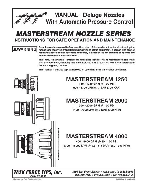
MANUAL: Deluge Nozzles<br />
With Automatic Pressure Control<br />
<strong>MASTERSTREAM</strong> NOZZLE SERIES<br />
INSTRUCTIONS FOR SAFE OPERATION AND MAINTENANCE<br />
WARNING<br />
Read instruction manual before use. Operation of this device without understanding the<br />
manual and receiving proper training is a misuse of this equipment. A person who has not<br />
read and understood all operating and safety instructions is not qualified to operate any<br />
of the Masterstream Series Nozzles.<br />
This instruction manual is intended to familiarize firefighters and maintenance personnel<br />
with the operation, servicing and safety procedures associated with the Masterstream<br />
Series firefighting nozzles.<br />
This manual should be kept available to all operating and maintenance personnel.<br />
<strong>MASTERSTREAM</strong> 1250<br />
150 - 1250 GPM @ 100 PSI<br />
600 - 4700 LPM @ 7 BAR (700 KPA)<br />
<strong>MASTERSTREAM</strong> 2000<br />
300 - 2000 GPM @ 100 PSI<br />
1100 - 7500 LPM @ 7 BAR (700 KPA)<br />
<strong>MASTERSTREAM</strong> 4000<br />
600 - 4000 GPM @ 80 - 120 PSI<br />
2300 - 15000 LPM @ 5.5 - 8.3 BAR (550 - 830 KPA)<br />
TASK FORCE TIPS, Inc.<br />
www.tft.com<br />
©Copyright Task Force Tips, Inc. 1999-2004<br />
2800 East Evans Avenue • Valparaiso , IN 46383-6940<br />
800-348-2686 • 219-462-6161 • Fax 219-464-7155<br />
LIM-030 May 11, 2004 Rev 03
TABLE OF CONTENTS<br />
1.0<br />
2.0<br />
2.1<br />
2.2<br />
2.3<br />
2.4<br />
2.5<br />
2.6<br />
3.0<br />
3.1<br />
3.2<br />
3.3<br />
3.4<br />
4.0<br />
5.0<br />
6.0<br />
MEANING OF SIGNAL WORDS<br />
GENERAL INFORMATION<br />
USE WITH SALT WATER<br />
VARIOUS MODELS AND TERMS<br />
HYDRAULIC INSTALLATION<br />
ELECTRIC INSTALLATION<br />
PATTERN CONTROL<br />
USE WITH FOAM<br />
2.6.1<br />
FOAMJET LX WITH <strong>MASTERSTREAM</strong> 1250 NOZZLE<br />
AUTOMATIC NOZZLE OPERATION<br />
FLOW CHARACTERISTICS OF <strong>MASTERSTREAM</strong> 1250 &<br />
<strong>MASTERSTREAM</strong> 2000<br />
FLOW CHARACTERISTICS OF <strong>MASTERSTREAM</strong> 4000<br />
DETERMINING FLOW WITH PRE-PIPED MONITORS<br />
STREAM TRAJECTORY DATA<br />
FLUSHING DEBRIS<br />
MAINTENANCE<br />
WARRANTY<br />
1.0 MEANING OF SIGNAL WORDS<br />
A safety related message is identified by a safety alert symbol and a signal word to indicate the level of risk involved with a<br />
particular hazard. Per ANSI standard Z535.4-1998 the definitions of the three signal words are as follows:<br />
DANGER<br />
WARNING<br />
CAUTION<br />
DANGER indicates an imminently hazardous situation which, if not avoided, will result in death or<br />
serious injury.<br />
WARNING indicates a potentially hazardous situation which, if not avoided, could result in death or<br />
serious injury.<br />
CAUTION indicates a potentially hazardous situation which, if not avoided, may result in minor or<br />
moderate injury.<br />
2<br />
©Copyright Task Force Tips, Inc. 1999-2004<br />
LIM-030 May 11, 2004 Rev 03
2.0 GENERAL INFORMATION<br />
The Task Force Tips Masterstream Series Nozzles are automatic pressure control deluge nozzles. These automatic nozzles operate by<br />
sensing the pressure at the nozzle's inlet and adjusting the discharge opening to maintain a constant pressure throughout the flow<br />
range of the nozzle. While flowing, the stream pattern can be varied from wide fog to straight stream. Trapped debris can be removed<br />
without the use of tools.<br />
These nozzles are constructed of hardcoat anodized aluminum and UV resistant rubber. Their rugged construction is compatible with<br />
the use of fresh water as well as firefighting foam solutions. A summary of each nozzle's characteristics is shown in the table below.<br />
FLOW FLOW PRESSURE PRESSURE STANDARD<br />
SERIES (GPM) (LPM) (PSI) (BAR, KPA/100) COUPLING<br />
<strong>MASTERSTREAM</strong> 1250 150-1250 600-4700 100 7 2.5" NH FEMALE<br />
<strong>MASTERSTREAM</strong> 2000 300-2000 1100-7500 100 7 3.5" NH FEMALE<br />
<strong>MASTERSTREAM</strong> 4000 600-4000 2300-15000 80-120 5.5-8.3 6" ANSI 150 FLANGE<br />
NOTES ON ABOVE TABLE:<br />
Other threads, coupling sizes or connector styles can be specified at time of order.<br />
Masterstream 1250 nozzle is also available in selectable gallonage or fixed orifice models. See catalog for details.<br />
Masterstream 4000 nozzle is field adjustable within the range of pressures shown.<br />
For long term installations, it is recommended that the threads be greased before installing the nozzle.<br />
OPERATING NOTE ABOUT AUTOMATIC NOZZLES: The automatic nozzle is considerably different than "conventional" nozzles<br />
because of basic changes in the operating principle. These differences not only assure the most effective operation under a variety of<br />
conditions, but will also utilize the available water supply most efficiently. It is important that nozzle operators, pump operators, and<br />
officers be fully aware of these differences. Therefore, proper instruction is required for safe and effective operations.<br />
WARNING<br />
CAUTION<br />
CAUTION<br />
WARNING<br />
WARNING<br />
This equipment is intended for use by trained personnel for firefighting. Their use for other<br />
purposes may involve hazards not addressed by this manual. Seek appropriate guidance and<br />
training to reduce risk of injury.<br />
Nozzle must be properly connected. Mismatched or damaged threads may cause nozzle to leak or<br />
uncouple under pressure and could cause injury.<br />
Do not couple aluminum to brass. Dissimilar metals coupled together can cause galvanic corrosion<br />
that can result in inability to unscrew threads or complete loss of thread engagement.<br />
Injury can occur from an inadequately supported nozzle. The mounting must be capable of<br />
supporting the nozzle reaction force which can be in excess of 2300 lbs (4000 GPM at 120 PSI).<br />
Some volatile liquids can be ignited by static discharge.<br />
Static build-up can occur from:<br />
Electrochemical separation of charge as water drains through low conductivity, refined<br />
products.<br />
Applying foam over a low conductivity liquid of sufficient depth to retain the charge created<br />
as the foam blanket drains.<br />
1<br />
Streaming currents as water or foam is introduced into the storage tank.<br />
WARNING<br />
Water is a conductor of electricity. Application of water solutions on high voltage equipment can<br />
cause injury or death by electrocution. The amount of current that may be carried back to the nozzle<br />
will depend on the following factors:<br />
<br />
<br />
<br />
<br />
<br />
Voltage of the line or equipment<br />
Distance from the nozzle to the line or equipment<br />
Size of the stream<br />
Whether the stream is solid or broken<br />
2<br />
Purity of the water<br />
1 Electrostatic Hazards of Foam Blanketing Operations by Peter Howels. Industrial Fire Safety July/August 1993<br />
2 The Fire Fighter and Electrical Equipment, The University of Michigan Extension Service, Fourth Printing 1983. Page 47.<br />
©Copyright Task Force Tips, Inc. 1999-2004<br />
3<br />
LIM-030 May 11, 2004 Rev 03
2.1 USE WITH SALT WATER<br />
Use with salt water is permissible provided nozzle is thoroughly cleaned with fresh water after each use. The service life of the<br />
nozzle may be shortened due to the effects of corrosion and is not covered under warranty.<br />
2.2 VARIOUS MODELS AND TERMS<br />
The spray pattern is changed from wide fog to straight stream by means of the "stream shaper". Models are available with five<br />
different methods to move the stream shaper as shown in figures 1A - 1E. See catalog for model numbers and details.<br />
Halo Ring<br />
Coupling<br />
Stream Shaper Serial Number Bumper<br />
Fig 1A Stream Shaper moved<br />
manually by rotating "halo ring"<br />
Fig 1B Stream Shaper moved<br />
manually by rotating "bumper"<br />
Hydraulic Ports<br />
<strong>Manual</strong> Override Knob<br />
(Masterstream 1250 &<br />
Masterstream 2000 Only)<br />
Fig 1C Stream Shaper moved<br />
remotely by hydraulics<br />
Lever<br />
Hold lever down and turn knob<br />
for manual override.<br />
Fig 1D Stream Shaper moved<br />
remotely by electricity (12-24 volts)<br />
4<br />
©Copyright Task Force Tips, Inc. 1999-2004<br />
Fig 1E Stream Shaper moved<br />
by linear (push/pull) motion<br />
from user's mechanism<br />
FIG 1 - Methods for Moving Stream Shaper<br />
LIM-030 May 11, 2004 Rev 03
2.3 HYDRAULIC INSTALLATION<br />
On nozzles with hydraulic stream shaper actuation, the hydraulic system is connected to the nozzle with two 1/8"-27 NPT (1/4”-18 NPT<br />
on Masterstream 4000) female ports on the filter block located on the nozzle's stream shaper. When the port on the left of the filter block<br />
(as seen from behind the nozzle) is pressurized, the shaper moves back into the wide fog position. Pressurizing the right port moves<br />
the shaper forward into straight stream. Hydraulic lines must be flexible to allow for movement of the stream shaper.<br />
Use only clean fluid compatible with Buna N Compound (Nitrile). System must be free from all dirt, chips and contaminants.<br />
Replacement filter elements are available from <strong>TFT</strong> (item #M160). Maximum hydraulic pressure is 1000 psi (70 bar, 7000 Kpa) for<br />
Masterstream 1250 or Masterstream 2000 Nozzles. (1500 psi, 105 bar, 10500 Kpa for Masterstream 4000 Nozzle).<br />
2.4 ELECTRIC INSTALLATION<br />
Nozzles with electric stream shaper actuation are shipped with a wiring diagram (<strong>TFT</strong> item #LIM-040). Other documentation is<br />
available on request. The actuator is not rated as ignition proof, explosion proof, or intrinsically safe. NOTE: Masterstream 1250 and<br />
Masterstream 2000 nozzles are equipped with manual override in case of electrical power failure. Refer to figure 1D for manual<br />
override instructions.<br />
WARNING<br />
The electric motor and other components are ignition sources. The electric stream shaper should<br />
be operated only in areas where there is adequate ventilation and no hazard of flammable vapor<br />
buildup.<br />
2.5 PATTERN CONTROL<br />
<strong>TFT</strong>'s Masterstream Series nozzles have full pattern control from straight stream to wide fog. On models with manual shapers, turning<br />
the stream shaper clockwise (as seen from the operating position behind the nozzle) moves the shaper to the straight stream position.<br />
Turning the stream shaper counterclockwise will result in an increasingly wider pattern.<br />
Since the stream trim point varies with flow, the nozzle should be "trimmed" after changing the flow to obtain the straightest and farthest<br />
reaching stream. To properly trim a stream, first open the pattern to narrow fog. Then close the stream to parallel to give maximum<br />
reach. Note: Turning the shaper further forward will cause stream crossover and reduce the effective reach of the nozzle.<br />
2.6 USE WITH FOAM<br />
The Masterstream Series nozzles may be used with foam solutions. Refer to fire service training for the proper use of foam.<br />
WARNING<br />
For Class B fires, lack of foam or interruption in the foam stream can cause a break in the foam<br />
blanket and greatly increase the risk of injury or death. Assure that:<br />
Application rate is sufficient (see NFPA 11 or foam manufacturer's recommendations).<br />
Enough concentrate is on hand to complete task (see NFPA for minimum duration time<br />
requirements).<br />
Foam logistics have been carefully planned. Allow for such things as:<br />
Storage of foam in a location not exposed to the hazard it protects.<br />
Personnel, equipment and technique to deliver foam at a rapid enough rate.<br />
Removal of empty foam containers.<br />
Clear path to deliver foam, as hoses and other equipment and vehicles are deployed.<br />
WARNING<br />
Improper use of foam can result in injury or damage to the environment. Follow foam<br />
manufacturer's instructions and fire service training to avoid:<br />
Using wrong type of foam on a fire, i.e. Class A foam on a Class B fire.<br />
Plunging foam into pools of burning liquid fuels.<br />
Causing environmental damage.<br />
Directing stream at personnel.<br />
WARNING<br />
There is a wide variety of foam concentrates. Each user is responsible for verifying that any foam<br />
concentrate chosen to be used with this unit has been tested to assure that the foam obtained is<br />
suitable for the purpose intended.<br />
©Copyright Task Force Tips, Inc. 1999-2004<br />
5<br />
LIM-030 May 11, 2004 Rev 03
2.6.1 FOAMJET LX WITH <strong>MASTERSTREAM</strong> 1250 NOZZLE<br />
To increase the expansion ratio, Task Force Tips "Foamjet LX" (model FJ-LX-M) may be used with the Masterstream 1250 nozzle. This<br />
low expansion foam tube attaches and detaches quickly from the nozzle. Adjust nozzle spray pattern to give best foam quality. Note:<br />
As expansion ratio is increased, the reach of the nozzle will be decreased due to the greater amount of bubbles in the stream and their<br />
inability to penetrate the air. Generally the reach with foam is approximately 10% less than with water only. Actual results will vary based<br />
on brand of foam, hardness of water, temperature, etc.<br />
3.0 AUTOMATIC NOZZLE OPERATION<br />
Automatic nozzles operate by sensing the pressure at the nozzle's inlet and adjusting the discharge opening to maintain a constant<br />
pressure throughout the flow range of the nozzle. For example, when the pressure at the inlet increases, the exit area is automatically<br />
increased until the inlet pressure returns to the nominal pressure of the nozzle.<br />
Note: Inlet pressure of a Masterstream Series nozzle will stabilize at the nominal pressure (within 5%). This stabilization may take as<br />
long as half a minute after a change in inlet pressure.<br />
3.1 FLOW CHARACTERISTICS OF <strong>MASTERSTREAM</strong> 1250 AND <strong>MASTERSTREAM</strong> 2000<br />
Within its flow range, the Masterstream 1250 and Masterstream 2000 automatic nozzles operate at the nominal pressure of 100<br />
PSI (7 BAR, 700 KPA). Figures 2A and 2B show typical performance of these nozzles.<br />
WARNING<br />
An inadequate supply of nozzle pressure and/or flow will cause an ineffective stream and can result<br />
in injury, death or loss of property.<br />
FLOW (LPM)<br />
0<br />
2000<br />
4000<br />
6000<br />
PRESSURE (PSI)<br />
160<br />
140<br />
120<br />
100<br />
80<br />
60<br />
40<br />
20<br />
OPERATING ENVELOPE<br />
PER NFPA 1964<br />
10<br />
8<br />
6<br />
4<br />
2<br />
PRESSURE (BAR, KPA/100)<br />
0 0<br />
0 200 400 600 800 1000 1200 1400 1600 1800 2000<br />
FLOW (GPM)<br />
FIG 2A - Masterstream 1250 Pressure Performance<br />
6<br />
PRESSURE (PSI)<br />
0<br />
160<br />
140<br />
120<br />
100<br />
80<br />
60<br />
40<br />
20<br />
©Copyright Task Force Tips, Inc. 1999-2004<br />
2000<br />
FLOW (LITERS/MIN)<br />
4000 6000 8000<br />
10000<br />
OPERATING ENVELOPE<br />
PER NFPA 1964<br />
0 0<br />
0 400 800 1200 1600 2000 2400 2800<br />
FLOW (GPM)<br />
FIG 2B - Masterstream 2000 Pressure Performance<br />
10<br />
8<br />
6<br />
4<br />
2<br />
PRESSURE (BAR, KPA/100)<br />
LIM-030 May 11, 2004 Rev 03
3.2 FLOW CHARACTERISTICS OF <strong>MASTERSTREAM</strong> 4000<br />
The Masterstream 4000's nozzle pressure is user adjustable from 80 to 120 PSI (5.5-8.3 BAR, 550-830 KPA). Pressure adjustment is<br />
made by turning a knob, on the front of the nozzle, to the desired pressure setting. The Masterstream 4000 will operate at the set<br />
pressure anywhere within its flow range of 600 to 4000 GPM (2300-15000 LPM). Figure 3 shows typical performance of the<br />
Masterstream 4000 nozzle.<br />
FLOW (LITERS/MIN)<br />
0 5000 10000 15000 20000<br />
PRESSURE (PSI)<br />
160<br />
140<br />
120<br />
100<br />
80<br />
60<br />
40<br />
20<br />
0<br />
120 PSI SETTING<br />
110 PSI SETTING<br />
8<br />
6<br />
100 PSI SETTING<br />
90 PSI SETTING 4<br />
FLOW RANGE<br />
80 PSI SETTING<br />
2<br />
0<br />
0 1000 2000 3000 4000 5000 6000<br />
FLOW (GPM)<br />
FIG 3 - Masterstream 4000 Pressure Performance<br />
10<br />
PRESSURE (BAR, KPA/100)<br />
3.3 DETERMINING FLOW WITH PRE-PIPED MONITORS<br />
The simplest procedure to determine flow with automatic nozzles is with a flow meter. If a flow meter is unavailable, then the flow may<br />
be estimated using pressure loss data between the nozzle and an in-line pressure gauge at the pump or considerably upstream from<br />
the nozzle. Data is taken with a smooth bore nozzle and handheld pitot gauge. Note: Equations assume no substantial change in<br />
elevation between in-line pressure gauge and nozzle.<br />
Step1: Determine flow of smooth bore nozzle.<br />
Flow water with a smooth bore nozzle and record the nozzle's size, pitot pressure and in-line pressure gauge reading. The smooth<br />
bore nozzle's flow is calculated from the Freeman formula:<br />
2<br />
Q =FxD P<br />
smooth<br />
pitot<br />
Where: F = 29.71 for English units (GPM, INCHES, PSI)<br />
F = .667 for metric units (LPM, MM, BAR) Note: 1 BAR=100 KPA<br />
Qsmooth<br />
flow in GPM (or LPM)<br />
D exit diameter in INCHES (or MM)<br />
Ppitot<br />
pitot pressure in PSI (or BAR)<br />
Step 2: Find pressure loss constant.<br />
Using the results from step 1, use the following equation to calculate the pressure loss constant between the in-line pressure<br />
gauge and the nozzle:<br />
C=<br />
P<br />
Q 2 smooth<br />
in-line<br />
- P<br />
pitot<br />
Where: C<br />
2 2<br />
piping pressure loss constant in GPM /PSI (or LPM /BAR)<br />
©Copyright Task Force Tips, Inc. 1999-2004<br />
7<br />
LIM-030 May 11, 2004 Rev 03
Step 3: Calculate flow with automatic nozzle.<br />
Using the pressure loss constant from step 2 and the following equation, the flow with an automatic nozzle can be calculated for your<br />
particular installation.<br />
Q = (P - P )C<br />
auto in-line auto<br />
Where:<br />
Q<br />
P<br />
auto<br />
auto<br />
automatic nozzle flow in GPM (or LPM)<br />
nominal nozzle operating pressure in PSI (or BAR)<br />
Mount a graph or table of the results adjacent to the in-line pressure gauge. Deliver any desired flow by adjustment of pump pressure.<br />
3.4 STREAM TRAJECTORY DATA<br />
Figures 4A and 4B give the stream trajectory for the Masterstream Series nozzles at various flows.<br />
Notes on trajectory graphs:<br />
• Graphs show approximate effective stream trajectory at 30 degrees elevation in no wind<br />
conditions. Distance to last water drops approximately 10% farther.<br />
• Trajectories shown are for water. The addition of foam is expected to decrease the reach by 10%.<br />
• Tail or head winds of 20 MPH (30 KPH) may increase or decrease the range approximately 30%.<br />
• Stream trajectory of Masterstream 4000 based on "The Trajectories of Large Fire Fighting Jets" by A.P. Hatton<br />
and M.J. Osborne, Reference: "The International Journal of Heat and Fluid Flow", Vol 1 No 1.<br />
VERTICAL DISTANCE (FEET)<br />
0<br />
10<br />
20<br />
30<br />
METERS<br />
40 50<br />
80<br />
70<br />
20<br />
60 <strong>MASTERSTREAM</strong> 1250, 100 PSI (7 BAR, 700 KPA )<br />
50<br />
D<br />
40<br />
10<br />
30<br />
20<br />
A<br />
E<br />
B<br />
10<br />
C<br />
0 0<br />
0 20 40 60 80 100 120 140 160 180 200 220 240 260 280 300<br />
HORIZONTAL DISTANCE (FEET)<br />
60<br />
70<br />
80 90<br />
METERS<br />
CURVE<br />
A<br />
B<br />
C<br />
D<br />
E<br />
CURVE<br />
A<br />
B<br />
C<br />
D<br />
E<br />
GPM<br />
FLOW<br />
300<br />
400<br />
500<br />
800<br />
1000<br />
LPM<br />
FLOW<br />
1100<br />
1500<br />
1900<br />
3000<br />
3800<br />
LBS<br />
REACTION<br />
150<br />
200<br />
260<br />
400<br />
510<br />
KGF<br />
REACTION<br />
70<br />
90<br />
120<br />
180<br />
230<br />
VERTICAL DISTANCE (FEET)<br />
80<br />
70<br />
60<br />
50<br />
40<br />
30<br />
20<br />
10<br />
0<br />
METERS<br />
0 10 20 30 40 50 60 70 80 90<br />
<strong>MASTERSTREAM</strong> 2000, 100 PSI (7 BAR, 700 KPA)<br />
A<br />
0 20 40 60 80 100 120 140 160 180 200 220 240 260 280 300<br />
HORIZONTAL DISTANCE (FEET)<br />
B<br />
C<br />
D<br />
E<br />
20<br />
10<br />
0<br />
METERS<br />
CURVE<br />
A<br />
B<br />
C<br />
D<br />
E<br />
CURVE<br />
A<br />
B<br />
C<br />
D<br />
E<br />
GPM<br />
FLOW<br />
300<br />
600<br />
1000<br />
1500<br />
2000<br />
LPM<br />
FLOW<br />
1100<br />
2300<br />
3800<br />
5700<br />
7500<br />
LBS<br />
REACTION<br />
160<br />
300<br />
510<br />
760<br />
1000<br />
KGF<br />
REACTION<br />
70<br />
140<br />
230<br />
340<br />
450<br />
FIG 4A - Masterstream 1250 and Masterstream 2000 Stream Trajectory<br />
8<br />
©Copyright Task Force Tips, Inc. 1999-2004<br />
LIM-030 May 11, 2004 Rev 03
VERTICAL DISTANCE (FEET)<br />
METERS<br />
0 20<br />
40<br />
60 80 100 120<br />
100<br />
30<br />
80 <strong>MASTERSTREAM</strong> 4000, 80 PSI (5.5 BAR, 550 KPA)<br />
60<br />
D<br />
20<br />
40<br />
A<br />
E<br />
10<br />
20<br />
B<br />
0<br />
C<br />
0<br />
0 40 80 120 160 200 240 280 320 360 400<br />
HORIZONTAL DISTANCE (FEET)<br />
METERS<br />
CURVE<br />
A<br />
B<br />
C<br />
D<br />
E<br />
CURVE<br />
A<br />
B<br />
C<br />
D<br />
E<br />
GPM<br />
FLOW<br />
600<br />
1000<br />
2000<br />
3000<br />
4000<br />
LPM<br />
FLOW<br />
2300<br />
3800<br />
7600<br />
11000<br />
15000<br />
LBS<br />
REACTION<br />
280<br />
470<br />
950<br />
1400<br />
1900<br />
KGF<br />
REACTION<br />
130<br />
210<br />
430<br />
640<br />
860<br />
VERTICAL DISTANCE (FEET)<br />
100<br />
80<br />
60<br />
40<br />
20<br />
0<br />
METERS<br />
0 20 40 60 80<br />
100 120<br />
<strong>MASTERSTREAM</strong> 4000, 100 PSI (7 BAR, 700 KPA)<br />
A<br />
B<br />
0 40 80 120 160 200 240 280 320 360 400<br />
HORIZONTAL DISTANCE (FEET)<br />
C<br />
D<br />
E<br />
30<br />
20<br />
10<br />
0<br />
METERS<br />
CURVE<br />
A<br />
B<br />
C<br />
D<br />
E<br />
CURVE<br />
A<br />
B<br />
C<br />
D<br />
E<br />
GPM<br />
FLOW<br />
600<br />
1000<br />
2000<br />
3000<br />
4000<br />
LPM<br />
FLOW<br />
2300<br />
3800<br />
7600<br />
11000<br />
15000<br />
LBS<br />
REACTION<br />
320<br />
530<br />
1100<br />
1600<br />
2100<br />
KGF<br />
REACTION<br />
150<br />
240<br />
500<br />
730<br />
950<br />
VERTICAL DISTANCE (FEET)<br />
METERS<br />
0 20 40 60 80<br />
100 120<br />
100<br />
90<br />
80 <strong>MASTERSTREAM</strong> 4000, 120 PSI (8.3 BAR, 830 KPA)<br />
70<br />
60<br />
C<br />
50<br />
40<br />
D<br />
30<br />
A<br />
E<br />
20<br />
B<br />
10<br />
0<br />
0 40 80 120 160 200 240 280 320 360 400<br />
HORIZONTAL DISTANCE (FEET)<br />
30<br />
20<br />
10<br />
0<br />
METERS<br />
CURVE<br />
A<br />
B<br />
C<br />
D<br />
E<br />
CURVE<br />
A<br />
B<br />
C<br />
D<br />
E<br />
GPM<br />
FLOW<br />
600<br />
1000<br />
2000<br />
3000<br />
4000<br />
LPM<br />
FLOW<br />
2300<br />
3800<br />
7600<br />
11000<br />
15000<br />
LBS<br />
REACTION<br />
350<br />
580<br />
1200<br />
1700<br />
2300<br />
KGF<br />
REACTION<br />
160<br />
260<br />
550<br />
770<br />
1000<br />
©Copyright Task Force Tips, Inc. 1999-2004<br />
FIG 4B - Masterstream 4000 Trajectory<br />
9<br />
LIM-030 May 11, 2004 Rev 03
4.0 FLUSHING DEBRIS<br />
Debris in the water may get caught inside the nozzle. This trapped material will cause poor stream quality, shortened reach and<br />
reduced flow. To remove debris trapped in the nozzle:<br />
1. Shut off flow to the nozzle.<br />
2. Move the stream shaper to the wide fog position.<br />
3. Carefully unscrew and remove the nozzle's piston/cylinder.<br />
Notes on Masterstream 1250 Nozzle:<br />
• The cylinder is under about 25 lbs (11Kgf) of spring force. The spring must be<br />
compressed to reinstall.<br />
• A long white push rod is part of the cylinder assembly. Pull cylinder straight out until push<br />
rod clears shaft.<br />
Notes for Masterstream 2000 & Masterstream 4000 Nozzles:<br />
• The cylinder and piston will come out as a unit.<br />
• Remove the small spring and stainless steel poppet from the center of the shaft.<br />
4. Remove debris.<br />
5. Reassemble the nozzle.<br />
Figures 5A, 5B & 5C show the pieces that are removed during the flush procedure.<br />
WARNING<br />
Large amounts of debris may be unflushable and can reduce the flow of the nozzle resulting in an<br />
ineffective flow. In the event of a blockage, it may be necessary to retreat to a safe area.<br />
PISTON<br />
RETURN SPRING<br />
PUSH ROD<br />
CYLINDER<br />
SPRAY LUBE<br />
SHAFT<br />
LUBE<br />
LUBE<br />
LUBE<br />
FIG 5A - Masterstream 1250 Front End Parts<br />
10<br />
©Copyright Task Force Tips, Inc. 1999-2004<br />
LIM-030 May 11, 2004 Rev 03
LUBE LUBE LUBE<br />
CONTROL<br />
SPRING<br />
SHAFT<br />
LUBE<br />
POPPET<br />
CYLINDER<br />
RETURN<br />
SPRING<br />
PISTON<br />
FIG 5B - Masterstream 2000 Nozzle Front End Parts<br />
LUBE LUBE LUBE<br />
RETURN<br />
SPRING<br />
SHAFT<br />
POPPET<br />
CONTROL<br />
SPRING<br />
LUBE<br />
CYLINDER<br />
PISTON<br />
FIG 5C - Masterstream 4000 Nozzle Front End Parts<br />
©Copyright Task Force Tips, Inc. 1999-2004<br />
11<br />
LIM-030 May 11, 2004 Rev 03
5.0 MAINTENANCE<br />
When reassembling the nozzle after repairs or for preventive maintenance, coat the seal on the piston, the inner bore of the cylinder<br />
and the shaft slide surface with a waterproof lubricant such as Dow Corning #44 Silicone Grease. Lubrication is required to assure<br />
continued smooth operation. The frequency of lubrication will depend on frequency of usage and storage conditions. Nozzles must be<br />
checked regularly to assure proper operation. See figures 5A, 5B and 5C for the nozzle lubrication points.<br />
STORAGE: Store the Masterstream 4000 Hydraulic Nozzle in the Full Fog (retracted) position.<br />
Contact factory for parts lists and exploded views for particular models. Each nozzle is identified by a serial number located on the<br />
nozzle's stream shaper (see figure 1).<br />
6.0 WARRANTY<br />
Task Force Tips, Inc., 2800 East Evans Avenue, Valparaiso, Indiana 46383-6940 ("<strong>TFT</strong>") warrants to the original purchaser of its<br />
Masterstream Series nozzles ("equipment"), and to anyone to whom it is transferred, that the equipment shall be free from defects in<br />
material and workmanship during the five (5) year period from the date of purchase.<br />
<strong>TFT</strong>'s obligation under this warranty is specifically limited to replacing or repairing the equipment (or its parts) which are shown by<br />
<strong>TFT</strong>'s examination to be in a defective condition attributable to <strong>TFT</strong>. To qualify for this limited warranty, the claimant must return the<br />
equipment to <strong>TFT</strong>, at 2800 East Evans Avenue, Valparaiso, Indiana 46383-6940, within a reasonable time after discovery of the defect.<br />
<strong>TFT</strong> will examine the equipment. If <strong>TFT</strong> determines that there is a defect attributable to it, <strong>TFT</strong> will correct the problem within a<br />
reasonable time. If the equipment is covered by this limited warranty, <strong>TFT</strong> will assume the expenses of repair.<br />
If any defect attributable to <strong>TFT</strong> under this limited warranty cannot be reasonably cured by repair or replacement, <strong>TFT</strong> may elect to<br />
refund the purchase price of the equipment, less reasonable depreciation, in complete discharge of its obligations under this limited<br />
warranty. If <strong>TFT</strong> makes this election, claimant shall return the equipment to <strong>TFT</strong> free and clear of any liens and encumbrances.<br />
This is a limited warranty. The original purchaser of the equipment, any person to whom it is transferred, and any person who is an<br />
intended or unintended beneficiary of the equipment, shall not be entitled to recover from <strong>TFT</strong> any consequential or incidental<br />
damages for injury to person and/or property resulting from any defective equipment manufactured or assembled by <strong>TFT</strong>. It is agreed<br />
and understood that the price stated for the equipment is in part consideration for limiting <strong>TFT</strong>'s liability. Some states do not allow the<br />
exclusion or limitation of incidental or consequential damages, so the above may not apply to you.<br />
<strong>TFT</strong> shall have no obligation under this limited warranty if the equipment is, or has been, misused or neglected (including failure to<br />
provide reasonable maintenance) or if there have been accidents to the equipment or if it has been repaired or altered by someone<br />
else.<br />
THIS IS A LIMITED EXPRESS WARRANTY ONLY. <strong>TFT</strong> EXPRESSLY DISCLAIMS WITH RESPECT TO THE EQUIPMENT ALL<br />
IMPLIED WARRANTIES OF MERCHANTABILITY AND ALL IMPLIED WARRANTIES OF FITNESS FOR A PARTICULAR<br />
PURPOSE. THERE IS NO WARRANTY OF ANY NATURE MADE BY <strong>TFT</strong> BEYOND THAT STATED IN THIS DOCUMENT.<br />
This limited warranty gives you specific legal rights, and you may also have other rights which vary from state to state.<br />
TASK FORCE TIPS, Inc.<br />
www.tft.com<br />
©Copyright Task Force Tips, Inc. 1999-2004<br />
2800 East Evans Avenue • Valparaiso , IN 46383-6940<br />
800-348-2686 • 219-462-6161 • Fax 219-464-7155<br />
LIM-030 May 11, 2004 Rev 03