Boring - Trenchless International
Boring - Trenchless International
Boring - Trenchless International

You also want an ePaper? Increase the reach of your titles
YUMPU automatically turns print PDFs into web optimized ePapers that Google loves.
In this issue | Colombia | South Africa | Canada | United States | Bahrain | Hong Kong | Germany | UK | Poland<br />
<strong>Boring</strong><br />
through Arizona<br />
NASTT 20 th Anniversary<br />
Asset Management<br />
Robotics<br />
April 2010<br />
Issue 7<br />
The official magazine of the ISTT
Dec Downey<br />
Istt Chairman<br />
<strong>International</strong> Society for<br />
<strong>Trenchless</strong> Technology<br />
www.istt.com<br />
info@istt.com<br />
Chairman: Dr Dec Downey<br />
dec.downey@jasonconsult.com<br />
Vice-Chairman: Dr Samuel Ariaratnam<br />
ariaratnam@asu.edu<br />
Executive Director: John Hemphill<br />
hemphill@istt.com<br />
Membership Secretary: Kyoko Kondo<br />
kondo@istt.com<br />
Executive Sub Committee<br />
Derek Choi: China<br />
Karel Franczyk: Czech Republic<br />
Gerda Hald: Denmark<br />
Norman Howell: United Kingdom<br />
Olga Martynyk: Ukraine<br />
Executive Director, ISTT<br />
308 S. Lee Street<br />
Alexandria, VA 22314<br />
United States<br />
Tel: +1 (703) 299-8484<br />
Kyoko Kondo (Ms.)<br />
Membership Secretary ISTT<br />
3rd Nishimura Bldg.,<br />
2-11-18, Tomioka, Koto-ku,<br />
Tokyo 135-0047, Japan<br />
Tel: +81 (3)5639 9970<br />
FAX: +81 (3)5639 9975<br />
Registered Address:<br />
15 Belgrave Square<br />
LONDON, SW1X 8PS<br />
UK<br />
Recently I looked back at past<br />
issues of the Underground Construction<br />
magazine Annual Municipal Survey and<br />
compared their estimates of trenchless<br />
activity in the water pipe rehabilitation for<br />
2004 and 2009 and I was pleasantly surprised<br />
to see significant growth, about 50<br />
per cent in the past five years. Perhaps<br />
the Dawn of the Replacement Era heralded<br />
by AWWA in 2001 is actually upon<br />
us – better late than never! Turning the<br />
pages of the industry magazines and journals;<br />
there certainly does seem to be an<br />
increase in activity levels with job stories<br />
and investment news on InsituGuard ® ,<br />
Aquapipe ® , SwageLining and various<br />
polymer spray linings. In the UK there<br />
are expectations in certain quarters that<br />
AMP5 will bring new emphasis on<br />
structural lining now that water quality<br />
programs have generally been completed<br />
and in Hong Kong there seems to be<br />
WSD projects on every street corner. The<br />
need, as pointed out by AWWA and the<br />
EPA Needs assessment, has been with<br />
us for some time and perhaps now we are<br />
seeing long overdue step change in installation<br />
works.<br />
Of course water mains renovation and<br />
replacement is an order of magnitude<br />
more difficult than corresponding sewer<br />
works, condition assessment and service<br />
reinstatements have always been more of<br />
a challenge in clean water and perhaps<br />
the absence of tools in the tool box has<br />
been an inhibiting factor. There has been<br />
progress in these areas – use of the<br />
iTAP ® type robot seems to be satisfactory<br />
and this is encouraging others to develop<br />
similar tools. Leak detection has been recognised<br />
as a particularly useful means of<br />
identiying stressed pipelines and various<br />
electromagnetic tools facilitate determination<br />
of residual life and help prioritise<br />
rehabilitation works. What else do we<br />
need to keep the momentum growing in<br />
this important sector of our business?<br />
Clear standard specification and<br />
approval procedures spring to mind. It<br />
seems to take an inordinate amount of<br />
time and money for the development of<br />
standards and approvals and these are<br />
vital to building the confidence in the<br />
utility owner community that will unlock<br />
the investments necessary to regenerate<br />
our water infrastructure. Standards are<br />
usually created by committees representing<br />
owners and suppliers, some groups are<br />
more welcoming to new entrants than others,<br />
some are heavy with vested interests,<br />
some seek to screen members by requiring<br />
that they represent industry groups.<br />
And here is my question to our membership<br />
– should ISTT seek to play a role in<br />
the developments of standards and exert<br />
influence on the approvals procedures?<br />
We can say that we represent all sides of<br />
the industry and we do have within our<br />
membership some of the most respected<br />
professionals who could play a part in the<br />
process subject of course to the establishment<br />
of proper practices and procedures<br />
within our organisation. In many cases the<br />
regulation of the industry is quite properly<br />
a local matter, though in Europe and<br />
through North America regional groups do<br />
the business. Where local determination is<br />
the preference could ISTT fulfil an advisory<br />
role to the national chapter or affiliated<br />
society? Certainly we get many enquiries<br />
concerning standards and approvals and<br />
it may be we should put our hand up and<br />
volunteer our potential contribution.<br />
These activities are energy and time<br />
intensive – we may need to consider<br />
resourcing an initiative if our membership<br />
considers that we should be more active<br />
in these areas. Fortunately ISTT has come<br />
though the lean times, at least for now, our<br />
successful events and training initiative<br />
mean that I hope to hand over a thriving<br />
organisation to Dr Sam Ariaratnam<br />
in November. Participation in standards<br />
development in partnership with member<br />
organisations may be a component<br />
of the outreach we should be funding.<br />
Let’s hear what you have to say. I write<br />
this hoping that we can develop a lively<br />
debate in the lead up to the Singapore<br />
<strong>International</strong> Conference where your ISTT<br />
Board members can be briefed to inform<br />
a consensus. I shall be visiting NASTT in<br />
Chicago, UKSTT at their annual dinner<br />
and ABRATT in Sao Paolo in the coming<br />
months so I hope to meet many members<br />
and hear your views.<br />
FROM the CHAIRMAN’s desk<br />
April 2010 - <strong>Trenchless</strong> <strong>International</strong><br />
1
Issue 7 - April 2010<br />
Great Southern Press<br />
Pty Ltd<br />
query@trenchlessinternational.com<br />
www.trenchlessinternational.com<br />
Editor-in-Chief: Chris Bland<br />
Managing Editor: Kate Pemberton<br />
Contributing Editors: Lyndsie Mewett,<br />
Lucy Rochlin<br />
Journalist: Lucy Eldred<br />
Sales Manager: Tim Thompson<br />
Senior Account Manager: David Marsh<br />
Sales Representative: Brett Thompson<br />
Design Manager: Michelle Bottger<br />
Designers: Venysia Kurniawan,<br />
Stephanie Rose, Sandra Noke, Ben Lazaro<br />
Event Co-ordinator: Stephanie Fielden<br />
GPO Box 4967<br />
Melbourne VIC 3001 Australia<br />
Tel: +61 39248 5100<br />
Fax: +61 3 9602 2708<br />
ISSN: 1836-3474<br />
In this issue | Colombia | South Africa | Canada | United States | Bahrain | Hong Kong | Germany | UK | Poland<br />
<strong>Boring</strong><br />
through Arizona<br />
NASTT 20 th Anniversary<br />
Asset Management<br />
Robotics<br />
The official magazine of the ISTT<br />
April 2010<br />
Issue 7<br />
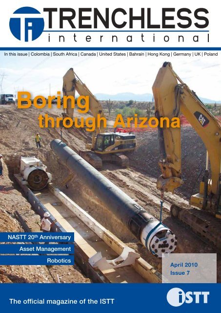
Cover shows the recent record-breaking auger bores<br />
have been accomplished across North America using<br />
Robbins Small <strong>Boring</strong> Units.<br />
This magazine is an official publication of the<br />
<strong>International</strong> Society for <strong>Trenchless</strong> Technology (ISTT)<br />
and is distributed free to members and other interested<br />
parties worldwide. It is also available on subscription.<br />
The publishers welcome editorial contributions from<br />
interested parties. However, neither the publishers nor<br />
the ISTT accept responsibility for the content of these<br />
contributions and the views contained therein which<br />
will not necessarily be the views of the publishers or<br />
the ISTT. Neither the publishers nor the ISTT accept<br />
responsibility for any claims made by advertisers.<br />
All communications should be directed to the publishers.<br />
Unless explicitly stated otherwise in writing, by<br />
providing editorial material to Great Southern Press<br />
(GSP), including text and images you are providing<br />
permission for that material to be subsequently used<br />
by GSP, whole or in part, edited or unchanged, alone or<br />
in combination with other material in any publication<br />
or format in print or online or howsoever distributed,<br />
whether produced by GSP and its agents and associates<br />
or another party to whom GSP has provided permission.<br />
REGULARS<br />
From the Chairman’s Desk 1<br />
Executive Director’s Report 4<br />
Upcoming Events 16<br />
About ISTT/Membership 61<br />
ISTT Membership/Directory 61<br />
Contacts and Addresses of Affiliated Societies 62<br />
Advertisers’ Index 64<br />
Subscription and Editorial Schedule 64<br />
News<br />
World wrap 6<br />
<strong>Trenchless</strong> update 8<br />
ISTT news<br />
Colombian Society digs deep 14<br />
Nominate now! 16<br />
South African award recognises HDD projects 18<br />
Outstanding support for No-Dig 2010 20<br />
North america<br />
Underground in North America 23<br />
Under Chicago 24<br />
NASTT celebrates 20 years 26<br />
Top 10 reasons to attend NASTT’s No-Dig 28<br />
Dissecting the record-breaker 30<br />
Powering New York State 32<br />
After the hurricane – rebuilding New Orleans 34<br />
Record breaking crossing in South Carolina 36<br />
GAS<br />
Peace River HDD intersect project 37<br />
asset management<br />
Hitting the 2030 target 41<br />
Hong Kong benefits from PE rehab 42<br />
projects<br />
Pumping station back in action 44<br />
Green machine saves the day 46<br />
pipe cleaning<br />
Coating shafts – substrate preparation perfected 47<br />
Cleaning pipes with pigs 48<br />
Bigger than Texas: PPIM puts pigs on show 51<br />
robotics<br />
Working together for trenchless advances 52<br />
Obama champions robotics 54<br />
industry review<br />
The state of road gully systems in Germany<br />
- Part 2 55<br />
Chemically restoring pipeline position 58<br />
2 3
executive director’s report<br />
April 2010 - <strong>Trenchless</strong> <strong>International</strong><br />
John Hemphill<br />
Istt Executive Director<br />
I am writing this report amid record<br />
snow that has blanketed the Washington<br />
DC area, realising that by the time<br />
you receive this issue of <strong>Trenchless</strong><br />
<strong>International</strong> the weather in most parts of<br />
the northern hemisphere will have turned<br />
decidedly warmer as the spring season<br />
approaches. Spring time is a time of<br />
renewal and ISTT renews its commitment<br />
to advancing trenchless education and<br />
training throughout the world. Beginning<br />
in April, ISTT member societies will host<br />
trenchless education and training activities<br />
in their respective regions. The year<br />
ends with ISTT hosting the 28th Annual<br />
<strong>International</strong> No-Dig Conference and<br />
Exhibition in Singapore. We have a full and<br />
exciting agenda planned for 2010.<br />
First out of the blocks is the Polish<br />
<strong>Trenchless</strong> Society (PFTT), which will host<br />
its IV Scientific and Training Conference<br />
– No-Dig Poland 2010 in Kielce on 27–29<br />
April. No-Dig Poland will also feature<br />
an indoor/outdoor exhibition. The event<br />
appears to be headed for a big success,<br />
with participation from outside Poland<br />
as well as from the Polish Government<br />
offices of Infrastructure and Environment.<br />
The month of May has two regional<br />
No-Digs. The North American Society<br />
(NASTT) will hold its 28th annual No-Dig<br />
Show on 2–7 May near Chicago. The Show<br />
will mark the 20th anniversary of NASTT.<br />
The NASTT No-Dig is the number one<br />
trenchless event in North America. I look<br />
forward to attending as both a member<br />
of NASTT and of ISTT. Across the pond,<br />
the Scandinavian Society (SSTT) will be<br />
hosting its annual No-Dig on 5–6 May in<br />
Bergen, Norway. The SSTT conference<br />
features 18 presentations on trenchless<br />
over the two days of the event including<br />
one by ISTT Executive Committee member<br />
Gerda Hald.<br />
June is a busy month with trenchless<br />
conferences taking place in Russia,<br />
Colombia and Ukraine. The Russian<br />
<strong>Trenchless</strong> Society (RSTT) is participating<br />
in the ECWTECH underground conference<br />
and exhibition to be held in Moscow<br />
on 1–4 June. The conference mirrors the<br />
2008 <strong>International</strong> No-Dig format. ISTT<br />
Chairman Dec Downey will participate<br />
in what promises to be a very exciting<br />
conference. The newly affiliated Colombia<br />
<strong>Trenchless</strong> Society (CISTT) will hold its<br />
first Underground Infrastructure and<br />
No-Dig Show on 3– 4 June in Cartagena.<br />
The CISTT plans to include an academic<br />
event as part of its conference as well as<br />
a demonstration of equipment and materials.<br />
Sam Ariaratnam, ISTT Vice Chairman<br />
and I plan to attend the conference. The<br />
Ukrainian <strong>Trenchless</strong> Society (UAMTT)<br />
will hold its annual conference on 11–12<br />
June in Odessa. I had the pleasure of<br />
participating in this conference last year.<br />
The UAMTT conference offers presentations<br />
covering trenchless technologies<br />
and methods, and academic research.<br />
At the mid-point of the year, the<br />
Brazilian <strong>Trenchless</strong> Society (ABRATT)<br />
will hold a No-Dig conference and exhibition<br />
in Sao Paulo on 21–22 July. I<br />
understand that the events exhibition area<br />
has been filled. The two-day conference<br />
will focus on municipal projects the first<br />
day and technical presentations on the<br />
second. Both Chairman Downey and Vice<br />
Chairman Ariaratnam plan to attend. On<br />
14–15 September, the Czech Republic<br />
(CzSTT) will hold its 15th annual No-Dig<br />
Conference and Exhibition in Liberec. The<br />
CzSTT event is off to a strong start with<br />
several sponsors already on board.<br />
The United Kingdom, Australia and<br />
Austria are hosting trenchless events in<br />
October. The United Kingdom (UKSTT)<br />
will hold the tenth in its highly successful<br />
biennial No-Dig Live event at Stoneleigh<br />
Park, near Coventry, 5–7 October – featuring<br />
a host of live demonstrations. The<br />
Australasian Society (ASTT) has scheduled<br />
“<strong>Trenchless</strong> Live 2010” in New South<br />
Wales on 17– 20 October. And the Austrian<br />
Society (AATT) has their annual trenchless<br />
conference set for 19–20 October in<br />
Saalfelden. These events offer an excellent<br />
opportunity to learn about the latest<br />
in trenchless developments.<br />
The year appropriately concludes with<br />
the 28th <strong>International</strong> No-Dig Conference<br />
and Exhibition on 8–10 November at<br />
the Suntec Singapore <strong>International</strong><br />
Convention and Exhibition Centre.<br />
Sponsorship commitments include<br />
Vermeer, who has signed up for the Gold<br />
level and Pure Technologies as Silver<br />
Sponsors. Exhibition space is filling up<br />
extremely fast and some 80 per cent of<br />
the available space is already booked by<br />
companies from Singapore, USA, China,<br />
Denmark, Germany, Malaysia, Australia,<br />
UK and Italy. Prospective exhibitors are<br />
encouraged to contact Westrade Group<br />
to reserve space before it’s too late!<br />
The conference has also attracted a high<br />
level of interest with some 50 abstracts<br />
received from all over the world, with a<br />
month to go before the deadline. No-Dig<br />
Singapore is supported by a number<br />
of influential organisations, including<br />
Singapore’s national water agency,<br />
Public Utility Board (PUB). The Institution<br />
of Engineers’ Singapore (IES) has also<br />
recently confirmed its official participation.<br />
Mark your calendar for this event and start<br />
making arrangements to attend – more<br />
information on the show website<br />
www.nodigsingapore.com<br />
As you can see, ISTT and its member<br />
societies offer many opportunities to<br />
participate in regional events throughout<br />
the world. Most of these events are well<br />
established and highly regarded for their<br />
technical content. We also have conferences<br />
scheduled in new world venues,<br />
which expands the trenchless community’s<br />
education and training reach and<br />
opportunities to further the use of trenchless<br />
methods.<br />
I hope you will be able to participate in<br />
at least one of these events. I know you<br />
will find it a rewarding experience.<br />
SIVAC® VACuum Sewer SyStem -<br />
the SuperIor AlternAtIVe to<br />
grAVIty flow SyStemS<br />
SIVAC ® fEAtURES At A GlAnCE<br />
• Economic pipe laying of vacuum pipes in flat and narrow trenches<br />
• <strong>Trenchless</strong> pipe laying with rinse drill operations (HDD)<br />
• Small pipe diameters (80–200 mm)<br />
• Cost reduction up to 40 % compared to gravity flow systems<br />
• Load relieving of clarification plant - drain water clarification only<br />
• Without lekage, hygienic due to the closed system<br />
• No pipe cleaning due to self-cleaning effect<br />
• Low operating costs<br />
SEKISUI SPR Group distributes the SIVAC ® technology exclusively. Take advantage<br />
of the new vacuum technology and make your connection: info@sekisuispr.com or<br />
mail@kmg.de. For further information visit www.sekisuispr.com.<br />
4
World wrap<br />
New Orleans rebuilding infrastructure<br />
following Hurricane Katrina<br />
The Sewerage and Water Board of New<br />
Orleans will spend $US196 million over the next<br />
five years to reduce sewage leaks from New<br />
Orleans’ deteriorating east bank sewer system.<br />
Thames Water awards contract for Lee Tunnel<br />
Thames Water has awarded a £400 million contract for the<br />
construction of the Lee Tunnel, located in East London,<br />
which will prevent sewage entering the River Lee. The contract<br />
is the largest ever awarded by Thames Water.<br />
Repairing Sarajevo’s sewers<br />
The World Bank has approved $US35 million in<br />
financing for the Sarajevo Waste Water Project to<br />
rehabilitate wastewater infrastructure in Sarajevo,<br />
a vast proportion of which was severely damaged<br />
in the 1992–95 conflict.<br />
Sweet home Chicago<br />
Chicago will play host to NASTT’s 20th<br />
Anniversary No-Dig Conference and<br />
Exhibition. See the North America feature<br />
on page 23 for more information.<br />
Insituform expands into<br />
South East Asia<br />
Insituform has expanded its operations<br />
into South East Asia following<br />
the acquisition of its former Singapore<br />
licensee, Insitu Envirotech.<br />
New trenchless society for Colombia<br />
The new ISTT affiliate, the Colombian Society for<br />
<strong>Trenchless</strong> Technology (CISTT) has been established<br />
in Colombia and will represent the industry<br />
in the region.<br />
News<br />
April 2010 - <strong>Trenchless</strong> <strong>International</strong><br />
New TBMs say Olá to Mexico City<br />
Three Robbins TBMs are on their way to<br />
Mexico City and will soon arrive to continue<br />
work on the Emisor Oriente project.<br />
Sewer rehab a priority for Bahrain<br />
The Bahraini Ministry of Works has announced<br />
that rehabilitating crumbling sewer mains will be<br />
a priority over the next 20 years. Turn to page 43<br />
to find out more.<br />
Keep up to date with this news and more by subscribing to the <strong>Trenchless</strong> <strong>International</strong> online update.<br />
Tite Lining a magnetite pipe<br />
United Pipeline Systems will reline mining<br />
pipelines for the Sino Iron Ore project in<br />
the Pilbara region of Western Australia as<br />
part of a $US10.9 million contract.<br />
www.trenchlessinternational.com<br />
news<br />
April 2010 - <strong>Trenchless</strong> <strong>International</strong><br />
6<br />
7
H E R R E N k N E C H T A G | U T I L I T y T U N N E L L I N G | T R A F F I C T U N N E L L I N G<br />
G E R M A N y<br />
8NEWS<br />
April 2010 - <strong>Trenchless</strong> <strong>International</strong><br />
8<br />
British floods strengthen the<br />
case for asset management<br />
The United Kingdom Environment Agency has released a report identifying<br />
the need to upgrade asset management processes around the country<br />
following damages caused by excessive flooding in 2007. Of the £4 billion<br />
worth of damages, £186 million is attributed to vital water infrastructure. In<br />
response to the report, British water authorities have recognised that much<br />
of their vital infrastructure, including distribution assets and treatment plants<br />
situated near rivers, require increased protection.<br />
NASTT rewards young trenchless professionals<br />
The North American Society for <strong>Trenchless</strong> Technology (NASTT) has<br />
announced a new scholarship program and a new award to honour<br />
the memory of two influential people in the trenchless industry and to<br />
encourage young professionals in the trenchless industry.<br />
The Michael E Ardent Memorial scholarship program includes five individual<br />
scholarships of $US5,000 each to be awarded to eligible students<br />
who are members of a current chapter of NASTT. The Trent Ralston Award<br />
for Young <strong>Trenchless</strong> Achievement has been created by the NASTT to<br />
acknowledge a young individual who has demonstrated excellence in the<br />
early stages of their career and has made a valuable contribution to the<br />
<strong>Trenchless</strong> Technology industry.<br />
EPA invests to renew or retire<br />
aging water infrastructure<br />
The EPA will invest $US10 million in the Aging Water Infrastructure<br />
Research Program to evaluate new technologies that will assist utilities in<br />
coping with aging and failing water and wastewater systems in the United<br />
States. The research will be undertaken by the US Water Environment<br />
Research Foundation and will examine innovative tools and procedures to<br />
improve the maintenance, rehabilitation, and replacement of aging sewer<br />
lines, water mains, and other components that constitute water and wastewater<br />
infrastructure in a cost-effective manner.<br />
Hawaii commended for green wastewater projects<br />
The Hawaii State Department of Health (DoH) has been recognised for<br />
its innovation and program management in underground infrastructure<br />
and its ability to exceed the American Recovery and Reinvestment Act’s<br />
Green Project Reserve requirements. One such green project is Honolulu’s<br />
Waimalu Sewer project, which is currently undertaking microtunelling<br />
operations.<br />
The late Trent Ralston.<br />
Can’t wait for the next edition of <strong>Trenchless</strong> <strong>International</strong>?<br />
Get the latest news at www.trenchlessinternational.com/news<br />
SUCCESSFUL OPERATION OF DIRECT PIPE ® FOR<br />
THE JEMGUM GAS STORAGE PROJECT.<br />
E M D E N | G E R M A N y<br />
PROJEcT DATA<br />
M-1295M, AVN1000XB<br />
Diameter: 1,295mm<br />
Max. torque: 150kNm<br />
H-107<br />
Pipe Thruster HK750PT<br />
Pipeline diameter: 48"<br />
Max. pulling force: 750t (7,500kN)<br />
Pipeline length: 283m<br />
Geology: sand, silt, clay, gravel,<br />
wood, stones<br />
Herrenknecht AG<br />
D-77963 Schwanau<br />
Phone + 49 7824 302-0<br />
Fax + 49 7824 3403<br />
marketing@herrenknecht.com<br />
www.herrenknecht.com<br />
cONTRAcTOR<br />
Meyer & John<br />
GmbH & Co. KG<br />
Tief- und Rohrleitungsbau<br />
Subterranean storage caverns for natural gas are being built on the Ems River, near the city<br />
of Leer, in Northern Germany. This requires flushing out salt mines to produce large underground<br />
cavities. In order to discharge the concentrated saltwater (brine), a 42-kilometer long<br />
pipeline must be laid to the Outer Ems near the city of Emden – the last 283 meters of the<br />
outflow pipe at the “Rysumer Nacken” artificial dune field will be built using the new one-pass<br />
Direct Pipe® method developed by Herrenknecht.<br />
This innovative installation technology means that any disturbance of the delicate<br />
natural environment around the East Frisian mud flat can be kept as minimal as possible.<br />
Compared with conventional methods, Direct Pipe® does not require the costly and timeconsuming<br />
installation of steel sheet piles alongside the offshore route.<br />
With the help of a Pipe Thruster, the prefabricated pipe string will be pushed directly<br />
towards the inlet structure located in the Outer Ems. The excavation work can be carried out<br />
simultaneously by a tunnelling machine which is coupled to the pipeline and, after reaching<br />
the target, can be disconnected and removed.<br />
Direct Pipe® met the high expectations of all parties involved as far as both efficiency<br />
and environmental protection are concerned and also made a valuable contribution towards<br />
securing future supplies of natural gas.
Largest CIPP project in Ireland<br />
CIPP has been used to rehabilitate twin 1,350 mm diameter culverts<br />
crossing the Ballyogan Stream that were at risk of structural failure at<br />
the Ballyogan Landfill Site, just outside of Dublin, Ireland. Insituform<br />
Environmental Techniques were subcontracted to reline twin water culverts<br />
that convey the Ballyogan Stream through the 62 hectare landfill site.<br />
Rehabilitation works took place using two single shot installations, each<br />
271 metres long, using CIPP lining technology. The project was the largest<br />
CIPP lining job in Ireland to date.<br />
Considering trenchless under Victoria Harbour<br />
Tunnel boring, microtunnelling and HDD are all being considered for<br />
the construction of more than 20 kilometres of deep sewage tunnels under<br />
Hong Kong’s Victoria Harbour.<br />
Proponent AECOM will build a sewage conveyance system of deep tunnels<br />
to transport the remaining raw sewage for enhanced treatment and<br />
disinfection at the Stonecutters Island treatment facility. Upon completion,<br />
more than 20 kilometres of deep sewage tunnels will cover areas at a maximum<br />
depth of 130 metres below sea level.<br />
Can’t wait for the next edition of <strong>Trenchless</strong> <strong>International</strong>?<br />
Get the latest news at www.trenchlessinternational.com/news<br />
Precision.<br />
Accuracy.<br />
news<br />
Professionalism.<br />
HDD Guidance Services<br />
ParaTrack Distributor<br />
Drilling Tool Sales and Rental<br />
April 2010 - <strong>Trenchless</strong> <strong>International</strong><br />
10<br />
Can't wait for the next edition of <strong>Trenchless</strong> <strong>International</strong>? Get the latest news at<br />
www.trenchlessinternational.com/news<br />
Prime Horizontal Companies<br />
The Netherlands: +31 (0)251 271 790<br />
In USA: 1-570-675-0901<br />
www.primehorizontal.com
Jacking pipes under Warsaw<br />
Over 7 kilometres of pipes are being jacked under Warsaw as part of<br />
construction works for a water collector pipe for the Czajka wastewater<br />
treatment plant currently being constructed on the River Vistula in Poland.<br />
Divided into three sections, the first section is approximately 5.7 kilometres<br />
long and uses Hobas jacking pipes OD 3,000, which are to be installed<br />
along the right side of the Vistula.<br />
Singapore’s PUB awards CIPP contracts<br />
Singapore’s national water agency, the Public Utility Board (PUB), has<br />
awarded $US18.5 million worth of CIPP contracts to rehabilitate sewer lines.<br />
Recently acquired Insituform subsidiary, Insitu Envirotech, has been<br />
awarded four contracts totalling $US18.5 million to rehabilitate approximately<br />
50 miles of sewer pipelines in Singapore for the PUB.<br />
The works are a part of the PUB’s $US295 million rehabilitation program<br />
that began in 2009. The project will see the rehabilitation of over 700 miles<br />
of public sewers and 30 miles of pumping mains by 2014.<br />
Turn to page 20 for all the latest information on the upcoming<br />
<strong>International</strong> No-Dig 2010, to be held in Singapore in November.<br />
Can’t wait for the next edition of <strong>Trenchless</strong> <strong>International</strong>?<br />
Get the latest news at www.trenchlessinternational.com/news<br />
news<br />
April 2010 - <strong>Trenchless</strong> <strong>International</strong><br />
KA-TE PMO,<br />
the No. 1 in<br />
Robotic Sewer<br />
Rehabilitation<br />
KA-TE PMO AG / Schwerzistrasse 4 / CH-8807 Freienbach<br />
www.kate-pmo.ch / Telephone +41 (0) 55 415 58 58<br />
Test Winner IKT Repair<br />
Methods «Main Sewers»,<br />
July 2009<br />
Test Winner IKT Repair<br />
Methods «House Connections»,<br />
June 2004<br />
12
Colombian Society digs deep<br />
ISTT news<br />
April 2010 - <strong>Trenchless</strong> <strong>International</strong><br />
A new <strong>Trenchless</strong> Technology Society has been established in Colombia.<br />
The Colombian Institute of Subterranean Infrastructure Technologies and<br />
Techniques will encourage the use of trenchless solutions in the vibrant<br />
capital Bogotá and throughout the South American country.<br />
Colombian representatives<br />
were in attendance at the ISTT<br />
<strong>International</strong> No-Dig in Toronto in early<br />
2009. The affiliation of the Colombian<br />
Institute of Subterranean Infrastructure<br />
Technologies and Techniques (CISTT)<br />
was agreed upon, as well as a decision to<br />
celebrate the inaugural Colombian No-Dig<br />
in June 2010. The first CISTT meeting was<br />
held in 2009, attended by representatives<br />
from companies including Empresas<br />
Públicas de Medellín (EPM), Coninsa<br />
RAMONH, SYE, VE, Herrenknecht,<br />
SOLETANCHE, BESSAC, PAVCO and<br />
FLOWTITE.<br />
The ISTT and the CISTT have common<br />
aims concerned with advancing<br />
the science and practice of <strong>Trenchless</strong><br />
Technology.<br />
The Colombian trenchless industry is<br />
vibrant and growing. A successful course<br />
was held at the EAFIT University (Escuela<br />
de Administración y Finanzas de Medellín),<br />
called: Tecnologías de Excavación sin<br />
Zanja, or <strong>Trenchless</strong> Technology. The<br />
course was attended by 26 engineers<br />
belonging to several companies including<br />
EPM, E.S.P, Coninsa – Ramón H – S.A.<br />
and SYE Ingenieros.<br />
A number of projects have utilised<br />
<strong>Trenchless</strong> Technology to avoid surface<br />
disruption and complete projects on time<br />
and in budget. The CISTT will facilitate<br />
the continued growth of the trenchless<br />
industry.<br />
Fucha – Tunjuelo Interceptor<br />
The Fucha – Tunjuele Interceptor<br />
will transport wastewater from La<br />
Magdalena Reservoir to a sewerage<br />
treatment plant. This interceptor is<br />
9.4 kilometres long with a variable<br />
overburden of 8 and 15 metres and<br />
an internal diameter of 3.75 metres.<br />
The tunnel was constructed using an<br />
EPB Machine with precast segments,<br />
beginning 26 February 2007 and finishing<br />
in November 2009.<br />
This contract, design and construction,<br />
was executed by a consortium<br />
composed by Soletanche – Bachy<br />
– Conconcreto and the owner is the<br />
EAAB (Empresa de Acueducto y<br />
Alcantarillado de Bogotá).<br />
Pilot tube microtunnelling in<br />
Fontibón, Bogotá<br />
This microtunnelling project was<br />
designed and constructed in order<br />
to solve a problem the lack of capacity<br />
of a combined system and repair<br />
serious deterioration. The solution<br />
proposed was dividing stormwater<br />
from wastewater. The total length was<br />
21 kilometres, including 18 kilometres<br />
installed by trenchless methods<br />
through soft clay and sand. The diameter<br />
ranged from 400 to 1,800 mm.<br />
Prado Centro project<br />
The relining of a 149 metre tunnel<br />
system, with an external diameter<br />
of 1,700 mm, under one of the most<br />
important hospitals in Medellin was<br />
completed by hand excavation with<br />
steel support and the construction of<br />
a parallel pipeline to collect laterals<br />
from the hospital.<br />
The advantages of this project<br />
include:<br />
• Less environmental and social<br />
impact<br />
• Pilot project in Medellín<br />
• Less risk during construction<br />
• Standardised process,<br />
mechanical strength<br />
guaranteed<br />
• Parking and cab zone<br />
• Permanent access to the<br />
hospital.<br />
CIPP in Medellín – La Hueso<br />
Creek Project<br />
This CIPP project to rehabilitate<br />
the south pipe of La Hueso creek<br />
with a total length of 1,067 metres<br />
(3,500 feet) involved three different<br />
internal diameters: 700 mm, 800 mm,<br />
and 900 mm.<br />
North Interceptor<br />
microtunnelling project in<br />
Medellín<br />
The North Interceptor will transport<br />
the wastewater and stormwater of<br />
several neighbourhoods to the local<br />
sewerage treatment plant. The<br />
pipeline will cross four rivers and<br />
necessitates 4.5 kilometres of branch<br />
interceptors.<br />
Construction of the 7.7 kilometre<br />
interceptor, with internal diameters of<br />
1.8, 2.2 and 2.4 metres, will be completed<br />
in two sections;<br />
Section one – Caribe Neighbourhood<br />
to Metro System workshops<br />
Section two – Western Regional<br />
roadway (projected) to treatment<br />
plant, incorporating four river<br />
crossings<br />
The average volume is 6.5 cubic<br />
metres per second and the maximum<br />
volume including all connections is<br />
13.5 cubic metres per second.<br />
Río Bogotá – Tunjuelo –<br />
Canoas microtunnelling<br />
interceptor<br />
The Río Bogotá – Tunjuelo –<br />
Canoas is an interceptor to continue<br />
the general sanitation project of the<br />
Bogotá River and its creeks and reservoirs.<br />
The length of the interceptor<br />
is 8.1 kilometres with an internal<br />
diameter of 4.2 metres and external<br />
diameter of 4.8 metres, to be<br />
installed in soft soil. The minimum<br />
overburden is 12 metres and the<br />
maximum overburden is 32 metres.<br />
Colombia is bordered by Venezuela,<br />
Brazil, Ecuador, Peru and Panama.<br />
Population: 45 million<br />
istt news<br />
April 2010 - <strong>Trenchless</strong> <strong>International</strong><br />
14<br />
15
Events<br />
ISTT news<br />
April 2010 - <strong>Trenchless</strong> <strong>International</strong><br />
Nominate now!<br />
The 2010 ISTT No-Dig Awards will be presented at the<br />
<strong>International</strong> No-Dig Conference and Exhibition, to be<br />
held in Singapore<br />
8–10 November. Submit your entry now!<br />
Awards may be made for entries in<br />
four categories for work completed during<br />
2009–10 as follows:<br />
• Academic research project or<br />
training aid/course<br />
• <strong>Trenchless</strong> project completed<br />
• New machine, tool, material, system<br />
or technique introduced<br />
• Student or young professional<br />
paper – members regularly<br />
enrolled in college or university, or<br />
spending at least half their time on<br />
academic course work.<br />
The aim of the ISTT is to promote<br />
the science and practice of <strong>Trenchless</strong><br />
Technology, and the Awards are intended<br />
to raise the profile and status of the<br />
Society and its award winners.<br />
The judges will be asked to consider:<br />
• Does the entry make a contribution<br />
to the advancement of <strong>Trenchless</strong><br />
Technology worldwide?<br />
• Does the entry contribute to protecting<br />
the environment and/or to<br />
reducing social costs?<br />
• Are the above benefits clear from<br />
the entry?<br />
• Is the entry commercially and economically<br />
practicable?<br />
• Is the entry innovative, ingenious,<br />
elegant or novel?<br />
• Will the award make an impact with<br />
the media, decision-makers and<br />
the general public?<br />
• Will the award impress ISTT<br />
members?<br />
• Has the entry been well explained<br />
and presented?<br />
The entry can relate to the practical use<br />
or development of trenchless systems, or<br />
to equipment for the installation or rehabilitation<br />
of underground utility networks.<br />
As examples they may be concerned with<br />
achievements in terms of:<br />
• Improved economy and competitiveness<br />
of trenchless installation<br />
• Length of speed of drive for installation,<br />
replacement or renovation<br />
• Accuracy or size of installation<br />
• Materials used<br />
• Ground conditions successfully<br />
dealt with<br />
• Improved acceptability for clients,<br />
operators and/or the environment<br />
• Underground detection, recording<br />
and mapping of obstacles, both<br />
natural and man-made<br />
• Health and safety of employees<br />
and the general public<br />
• Matters related to training in the<br />
field of trenchless work<br />
• Research into any of the topics<br />
that surround working on utilities<br />
underground.<br />
Entries are required to be submitted<br />
in English and should be prepared with<br />
the above criteria in mind to a maximum<br />
of 1,000 words in one of the standard<br />
electronic formats (for example MS Word,<br />
WordPerfect) supported by suitable illustrations.<br />
The illustrations should be in<br />
JPG format so that they can be circulated<br />
quickly to the judges. Further details are<br />
available from the ISTT.<br />
The closing date for entries is 30 July 2010. Entries should be<br />
submitted to the ISTT at info@istt.com<br />
No-Dig Poland 2010<br />
Kielce, Poland<br />
27–29 April 2010<br />
www.nodigpoland.tu.kielce.pl<br />
NASTT No-Dig Show 2010<br />
Chicago, United States<br />
2–7 May 2010<br />
www.nodigshow.com<br />
IFAT China<br />
4–6 May 2010<br />
Shanghai New <strong>International</strong> Expo Centre<br />
(SNIEC)<br />
www.ifat-china.com<br />
SSTT No-Dig show<br />
Bergen, Norway<br />
5–6 May 2010<br />
www.sstt.dk<br />
No-Dig Moscow 2010<br />
1–4 June 2010<br />
www.nodig2008.sibico.com<br />
CISTT No-Dig 2010<br />
Cartagena de Indias, Colombia<br />
2–4 June 2010<br />
UAMTT Conference<br />
Odessa, Ukraine<br />
11–12 June 2010<br />
Engineering 2010<br />
Tomaszowice, near Krakow<br />
16–18 June<br />
Singapore <strong>International</strong> Water Week<br />
Singapore<br />
28 June–2 July 2010<br />
www.siww.com.sg<br />
No-Dig Latin America<br />
Sao Paulo, Brazil<br />
21–22 July 2010<br />
www.abratt.org.br/nodig2010<br />
CzSTT No-Dig Conference and Exhibition<br />
Liberec, Czech Republic<br />
14–15 September 2010<br />
www.czstt.cz<br />
UKSTT No-Dig Live<br />
Coventry, UK<br />
5–7 October<br />
www.nodiglive.co.uk<br />
<strong>Trenchless</strong> Live 2010<br />
Coffs Harbour, New South Wales, Australia<br />
15–18 October 2010<br />
www.trenchless2010.com<br />
<strong>International</strong> No-Dig 2010<br />
Singapore<br />
8–10 November 2010<br />
www.nodigsingapore.com<br />
Vietwater 2010<br />
Ho Chi Minh City, Vietnam<br />
10–12 November 2010<br />
Bauma China<br />
Shanghai, China<br />
23–26 November 2010<br />
www.bauma-china.com<br />
<strong>International</strong> No-Dig 2011<br />
Berlin, Germany<br />
2–5 May 2011<br />
www.istt.com<br />
WASSER BERLIN 2–5 May 2011<br />
www.wasser-berlin.com<br />
<strong>International</strong> No-Dig 2012<br />
Sao Paulo, Brazil<br />
14–16 May 2012<br />
www.nodigshow2012.com<br />
INTERNATI ONAL<br />
Singapore<br />
N O<br />
- D<br />
I G<br />
2 0 1 0<br />
Supported by<br />
,<br />
2010 s world<br />
forum on<br />
trenchless<br />
technology<br />
28 TH <strong>International</strong> Conference & Exhibition<br />
8-10 November 2010 - Singapore<br />
■ Major Exhibition showcasing the very best<br />
products and services for the installation and<br />
refurbishment of underground utilities<br />
■ <strong>International</strong> Conference programme featuring the<br />
latest innovations and techniques<br />
For further information on exhibiting, attending the conference, or<br />
visiting the exhibition, keep up to date at www.nodigsingapore.com<br />
or contact the appointed organisers:<br />
All Enquiries: Westrade Group Ltd<br />
Tel: +44 (0) 845 094 8066<br />
Email: trenchless@westrade.co.uk<br />
www.nodigsingapore.com<br />
Organised by<br />
<strong>International</strong> Society for<br />
<strong>Trenchless</strong> Technology<br />
Held in<br />
16
istt news<br />
April 2010 - <strong>Trenchless</strong> <strong>International</strong><br />
South African award<br />
recognises HDD project<br />
A reticulation project in South Africa, using horizontal directional drilling to connect ten buildings in<br />
Johannesburg’s CBD, has received the 2009 SASTT Award for Excellence.<br />
The Joop van Wamelen SASTT Award<br />
was presented to Managing Member<br />
Sam Efrat and General Manager Marco<br />
Camarda of <strong>Trenchless</strong> Technologies cc<br />
at the SASTT Annual General Meeting<br />
by the outgoing SASTT President Johann<br />
Wessels. The award ceremony took place<br />
at the regional offices of Johannesburg<br />
Water in Midrand on 2 February 2010.<br />
Award ceremony L-R, Marco Camarda,<br />
Samuel Efrat and Johann Wessels.<br />
Fast facts<br />
• Contractor: <strong>Trenchless</strong><br />
Technologies cc<br />
• Employer: ABSA Bank<br />
Limited<br />
• Project Managers: Mokala<br />
Collins/JM Henrey &<br />
Associates Joint Venture<br />
• Consultants: Taemane/SDE<br />
and Asak/LC.<br />
The project<br />
The works involved connecting ten of<br />
ABSA Bank’s buildings in Johannesburg’s<br />
CBD with 100 underground sleeves for<br />
electricity, gas, fibre optic, as well as low<br />
temperature hot water and chilled water.<br />
Drilling took place from building basement-to-basement<br />
beneath the busy CBD<br />
roadways, at depths of up to 16 metres,<br />
using horizontal directional drilling.<br />
Sleeve diameters ranged in size from<br />
160, 225, 450, 500, 560 and 710 mm using<br />
PE 100 PN 8 HDPE pipe. The 160 mm and<br />
225 mm sleeves were installed in bundles<br />
of three, four or six pipes. The ten month<br />
contract had a value of R13 million<br />
($US1.7 million). The type of contract<br />
document used was the NEC3.<br />
Challenges and solutions<br />
The ABSA building’s basement floors<br />
were originally designed to support<br />
the weight of a typical sedan vehicle.<br />
Consequently the Terra-Jet 7520 automatic<br />
rod loading system was removed to<br />
decrease the machine weight and propping<br />
was undertaken from the floor below<br />
to support all areas over which the drill<br />
needed to travel into the required positions<br />
within basements.<br />
A floor to sprinkler height restriction<br />
required that all equipment be less than<br />
2.1 metres in height. Consequently the<br />
Terra-Jet 7520 was further modified by<br />
removing the operator cabin, rebuilding<br />
the hydraulic oil tank at a lower position<br />
and lowering the encapsulating body work<br />
such that the remodelled drill resembled a<br />
tank with a height of only 1.8 metres.<br />
The majority of the installations took<br />
place in clay whilst the remaining 20 were<br />
in rock. The presence of the rock necessitated<br />
the use of percussive hammer and<br />
rock reamers to expand the holes to the<br />
required diameters.<br />
Lateral support ground anchors were<br />
encountered during drilling on 26 of the<br />
Terra-Rock Air Percussion Head<br />
OD 95.<br />
TCI Roller low torque rock reamer.<br />
crossings. The presence and position of<br />
these were unforeseen, and resulted in<br />
the entanglement of drilling equipment<br />
in several instances. Drilling tools were<br />
pulled, pushed and rotated until they<br />
became free or broke the ground anchoring<br />
cables. In two instances the entangled<br />
cable would not break and an acetylene<br />
oxygen cutter was modified and inserted<br />
within the bore to cut the cable and free<br />
the drilling tools.<br />
In order to gain access to the drill face,<br />
coring to remove concrete lateral walls<br />
from 300 – 500 mm thick was required.<br />
Containment of the large volumes of bentonite<br />
and spoil was a necessity as the<br />
basements are maintained in a pristine<br />
condition and in daily use. This was made<br />
possible using specially constructed tanks<br />
and brick burms.<br />
The removal of bentonite to the surface<br />
was one of the greatest challenges the<br />
project faced. Initially pumping, which<br />
is by far the preferred method of spoil<br />
removal did not look feasible. This was<br />
due to requiring extremely long pipe<br />
lengths – of up to 600 metres – to remove<br />
the bentonite from basement-to-basement<br />
up the vehicular ramps. However, at the<br />
planning stage the idea was put forward<br />
Ground anchor in rocky bore.<br />
Pilot drill and bentonite collection.<br />
to core holes through the slabs and enable<br />
vertical pumping along the shortest<br />
route to reduce pumping lengths to less<br />
than 200 metres.<br />
For the first six months of contract no<br />
drilling was allowed during the ‘freeze<br />
period’ from the 26th of the preceding<br />
month to the 5th of the following month.<br />
This was to prevent any potential damage<br />
to cables and infrastructure during<br />
the busy end of month banking period.<br />
This resulted in a very tight work schedule<br />
necessitating crews to work day and night<br />
shifts, seven days a week.<br />
The location of drilling equipment on<br />
either side of the walls was required<br />
through concrete, rock and at depths of<br />
up to 16 metres. <strong>Trenchless</strong> Technology<br />
cc made use of the radio detection i-track<br />
system and tracked the equipment horizontally<br />
from the basements on either side<br />
of each crossing.<br />
Confined access into basements via<br />
vehicular ramps required short six metre<br />
lengths of HDPE pipe to be individually<br />
transported down into basements where<br />
they were butt-welded into long continuous<br />
lengths for installation.<br />
Whilst in the museum the only access<br />
was by means of a lift and pipe lengths<br />
were limited to three metres. Here, and<br />
in other confined and storage areas and<br />
plant rooms, the bentonite was collected<br />
in tanks and removed in ‘wheelie’ bins.<br />
In two instances the HDPE pipe was<br />
hammered into the completed bore from<br />
the drill machine side in a pipe ramming<br />
operation, as there was no access to pull<br />
the piping in from the opposite side of the<br />
bore.<br />
The benefits of using <strong>Trenchless</strong><br />
Technology for the ABSA project<br />
The installations were exceptionally<br />
deep, precluding conventional excavation<br />
methodology. There was no damage<br />
to roadways and existing buried infrastructure,<br />
nor was there any disruption<br />
to pedestrian and vehicular traffic in the<br />
busy CBD area. Cost savings were also<br />
significant when compared to other possible<br />
methodologies.<br />
Why HDD?<br />
HDD allowed the insertion of the preferred<br />
HDPE sleeves without requiring the<br />
installation of a temporary pipe or permanent<br />
rigid pipe, followed by the HDPE pipe<br />
installation. HDD required no thrust abutment<br />
wall, and also allowed for adequate<br />
steering accuracy. The equipment is selfpropelled<br />
and capable of drilling in a wide<br />
range of soil conditions including clay and<br />
rock. It is also sufficiently compact and<br />
manoeuvrable to be able to operate in the<br />
confined basement spaces.<br />
Six metre lengths of HDPE piping.<br />
<strong>Trenchless</strong> Technologies cc was established<br />
in 1991 and to date have completed<br />
over 220,000 metres of trenchless pipeline<br />
rehabilitation and new installation works.<br />
They have been the Southern African<br />
agent for Terra AG since 1993.<br />
Previous awards include the SAICE<br />
Pretoria Branch Award for Technical<br />
Maxi-Rig Directional Drills<br />
Auger <strong>Boring</strong> Machines<br />
Product Tooling & Accessories<br />
Mud Pump & Cleaning Systems<br />
Oil & Gas Drill Rigs<br />
Mid-Size Directional Drills<br />
Completed installation with basement<br />
returned to their pristine condition.<br />
Excellence in 2000, along with the City<br />
of Tshwane and consultants Bigen<br />
Africa, for the rehabilitation of sewers<br />
in Mamelodi. The SASTT Award<br />
of Excellence in 2007, along with<br />
Johannesburg Water and Consultants<br />
Vela VKE for the rehabilitation of sewers<br />
pipes in Klipspruit Basin.<br />
Exceptional Force … Reliable Results.<br />
For 40 years, customers worldwide have<br />
come to know American Augers as a<br />
dedicated manufacturer of underground<br />
technology equipment, which includes<br />
state-of-the-art horizontal directional<br />
drills, earth boring machines, mud pump<br />
and cleaning systems, oil and gas drill<br />
rigs, and various product tooling or<br />
accessory items. Each of the product<br />
categories produce equipment that<br />
maintains rugged, unsurpassed power,<br />
and industry leading designs.<br />
istt news<br />
April 2010 - <strong>Trenchless</strong> <strong>International</strong><br />
18<br />
AA Company island Ad TI.indd 1<br />
12/14/09 4:57 PM<br />
19
Outstanding support<br />
for No-Dig 2010<br />
istt news<br />
April 2010 - <strong>Trenchless</strong> <strong>International</strong><br />
20<br />
The international <strong>Trenchless</strong> Technology community<br />
is lining up in force to support the ISTT’s 28th Annual<br />
<strong>International</strong> No-Dig Conference and Exhibition, to be<br />
held in Singapore 8–10 November 2010.<br />
The Right Tool<br />
Manhole<br />
Renewal<br />
Tool Box<br />
Permacast® Liners<br />
Cor+Gard® Coatings<br />
Permaform ®<br />
Con MIC Shield®<br />
Calcium Aluminate Cements<br />
Water Plug & Patch<br />
COR+ROC Structual Polymer<br />
I & I Barrier®<br />
Top Seal TM CIPPChimney Liners<br />
Spray Equipment<br />
Applicators<br />
Worldwide in<br />
Denmark,<br />
Ireland, UK,<br />
Singapore,<br />
Israel,<br />
Norway,<br />
Sweden<br />
and USA.<br />
For Every Problem!<br />
AP/M PERMAFORM ®<br />
Fax: +515.276.1274 • www.permaform.net<br />
Headline sponsorship packages have been taken up<br />
by Vermeer and Pure <strong>International</strong> and key manufacturers from<br />
around the globe have already booked some 80 per cent of the<br />
available exhibition space. In addition to National Pavilions from<br />
Germany and Singapore, China is participating with a significant<br />
presence alongside individual representation from UK, North<br />
America, Denmark, Italy, Australia, Japan, UAE and Malaysia.<br />
The Conference call for papers has drawn more than 50 offers<br />
from potential presenters and Professor Sam Ariaratnam, Vice-<br />
Chairman of ISTT and head of the Program Committee said<br />
“We are delighted with the range of presentations that have<br />
been offered for the Singapore conference. This is the first time<br />
that ISTT has presented a conference in this location and I am<br />
confident that the program will have a wide appeal, not only<br />
to delegates from the Asia Pacific region, but also from ISTT<br />
affiliated members around the world – many of whom are already<br />
anticipating group delegations.”<br />
The closing date for papers is 15 March and the full Conference<br />
program is scheduled for publication in July.<br />
<strong>International</strong> No-Dig 2010 is organised by ISTT, who have<br />
engaged the official support of several influential organisations,<br />
including Singapore’s National Water Agency, PUB. They are<br />
also joined by the Institution of Engineers Singapore, Institution of<br />
Civil Engineers, Tunnelling & Underground Construction Society<br />
(Singapore) and the Malaysian Water Association.<br />
Singapore is a regional centre of excellence for <strong>Trenchless</strong><br />
Technology, established through many major microtunnelling<br />
projects undertaken by PUB. The ongoing sewer rehabilitation<br />
program continues today, as PUB maintains some 3,400 kilometres<br />
of public sewers and the current phase (2009–2014) will see<br />
the refurbishment of more than 1,000 kilometres of this network.<br />
For more information on exhibition space availability,<br />
sponsorship opportunities and the conference, contact<br />
Westrade Group Ltd Tel: +44 (0) 845 0948066<br />
Email: trenchless@westrade.co.uk Full details of<br />
<strong>International</strong> No-Dig 2010 are also to be found on the<br />
show website www.nodigsingapore.com<br />
The fastest way to bore through hard rock<br />
is with a Robbins SBU-A. Extreme conditions?<br />
The machine can bore up to 150 MPa UCS.<br />
Mixed ground? Just change the cutterhead.<br />
Talk with Robbins about leasing or buying the<br />
most cost-effective solution for your next project.<br />
Crack hard rock with confidence.<br />
therobbinscompany.com<br />
sbusales@robbinstbm.com<br />
+1 440.248.3303
Underground in<br />
North America<br />
North America is home to a diverse underground infrastructure industry. Here<br />
<strong>Trenchless</strong> <strong>International</strong> looks at innovative and record breaking projects, using<br />
a range of trenchless techniques, as well as providing an overview of NASTT’s<br />
No-Dig 2010.<br />
In 2010 NASTT turns 20 – congratulations! The Society’s No-Dig Conference and Exhibition,<br />
taking place in Chicago 2–7 May, will celebrate the achievements of the Society and the industry<br />
in North America. The event also serves the aims of the NASTT to promote the industry through<br />
events such as the Educational Fund Auction and the provision of scholarships and awards.<br />
Turn to page 26-29 to find out more about the event.<br />
Also in this North American feature;<br />
• Auger boring records in Kentucky, Ohio and Oregon<br />
• Optically guided, downhole hammers used to expand a substation in rural New York State<br />
• HDD crossings in New Orleans in the aftermath of Hurricane Katrina<br />
• The diversion of wastewater flows in South Carolina with HDD, using Fusible PVC pipe<br />
• An engineer’s perspective on the Peace River Intersect Project in Alberta Canada.<br />
For all the latest news, projects and technical article visit www.trenchlessinternational.com<br />
north america<br />
April 2010 - <strong>Trenchless</strong> <strong>International</strong><br />
23
Under Chicago<br />
Chicago, the Windy City, is situated on the south western shores of Lake Michigan and is the<br />
capital of Illinois. The city, founded in 1833, has depended on the lake for water and sanitation.<br />
Here <strong>Trenchless</strong> <strong>International</strong> provides an overview of the development of the city’s water and<br />
wastewater networks, as well as looking at current projects.<br />
Water works<br />
North america<br />
April 2010 - <strong>Trenchless</strong> <strong>International</strong><br />
Bordering on Illinois, Indiana,<br />
Michigan, and Wisconsin, Lake Michigan<br />
is the only Great Lake to be located<br />
entirely within the United States. It is the<br />
second largest Great Lake by volume,<br />
with a capacity of 1,180 cubic miles of<br />
water, and the third largest by area.<br />
The City of Chicago utilises Lake<br />
Michigan as its source of drinking water.<br />
Water is treated via two plants – the<br />
Jardine Water Purification Plant serves the<br />
northern areas of the City and suburbs,<br />
while the South Water Purification Plant<br />
serves the southern areas of the City and<br />
suburbs.<br />
Water is distributed throughout Chicago<br />
via century-old pipes that require ongoing<br />
maintenance. The City of Chicago commonly<br />
uses trenchless techniques such<br />
as sliplining and CIPP, together with CCTV<br />
inspection and condition assessment to<br />
inspect and maintain the system. In addition,<br />
the City has implemented the Tunnel<br />
and Reservoir Plan (TARP), also known<br />
as the Chicago Deep Tunnel, which aims<br />
to reduce flooding of the city and prevent<br />
raw sewerage from entering Lake<br />
Michigan by diverting the flow to holding<br />
reservoirs.<br />
In the pipeline –<br />
a short sewer history<br />
The Chicago Sewers Collection has collated<br />
a history of the development of the<br />
wastewater network.<br />
From the establishment of Fort Dearborn<br />
in 1803 along the Chicago River to the<br />
present day, water and sanitation have<br />
always been crucial to Chicago. Chicago’s<br />
low-lying location combined with the livestock<br />
and waste of the settlers resulted<br />
in a serious waste disposal problem. The<br />
Collection states that by 1845, Chicago<br />
was facing an environmental crisis and<br />
then experienced two cholera epidemics.<br />
In 1855, the Chicago City Council<br />
employed Boston engineer Ellis S<br />
Chesbrough to design the first comprehensive<br />
system of underground sewers in<br />
the United States. The Board of Sewerage<br />
Commissioners adopted Mr Chesbrough’s<br />
plan to drain sewage into the Chicago<br />
River, in order to limit the cost and extent<br />
of the proposed sewer system. The level<br />
of Chicago’s streets was raised from six<br />
to ten feet to accommodate sewer pipes,<br />
gas and water mains. Owners lifted buildings<br />
to meet the new street level; in some<br />
cases whole blocks were raised at a time.<br />
By 1930 Chicago’s sewer system<br />
was the most extensive in the world.<br />
Today the Chicago Department of Water<br />
Management continues to employ new<br />
technologies in inspection, materials and<br />
maintenance.<br />
Planning for future<br />
Despite the reversal of the Chicago<br />
River and the construction of the largest<br />
water treatment plant in the world, polluted<br />
combined sewer overflows (CSOs)<br />
persisted in Chicago throughout the first<br />
half of the 20th century.<br />
In 1972, in order to improve the Chicago<br />
Area Waterway System (CAWS), the TARP<br />
was adopted by the Metropolitan Water<br />
Reclamation District of Greater Chicago<br />
(MWRD).<br />
MWRD explained that construction of<br />
Phase 1, primarily for pollution control,<br />
began in 1975 and was completed in<br />
2006. The total length is 176 kilometres<br />
(109.4 miles) of deep, large diameter,<br />
rock tunnels providing 2.3 billion gallons<br />
of volume to capture CSOs. The tunnels<br />
were bored using tunnel boring machines<br />
(TBMs), with pipe diameters ranging from<br />
9–33 feet. MWRD says that the TARP tunnelling<br />
work led to major improvements to<br />
the TBMs, and pushed them beyond their<br />
then-proven capabilities. For example the<br />
Mainstream tunnel was mined three times<br />
faster than the 0.6 metres per<br />
hour that had been estimated<br />
in 1975.<br />
Mining records were set on many of the<br />
TARP contracts. On the last tunnel leg<br />
completed on the Calumet system (Little<br />
Calumet), the TBM crew broke several<br />
world records for a machine of its size.<br />
In addition to contributing to an increase<br />
the speed of mining, the TARP project<br />
has led to improvements in accuracy. The<br />
TBM used on the Little Calumet leg used<br />
a laser target system to permit continuous<br />
steering control and monitoring of line<br />
and grade – a huge improvement from<br />
the machines used on the first tunnels of<br />
the TARP, which had to be adjusted at the<br />
end of each push. Phase 2 of the TARP<br />
is in construction and is expected to be<br />
completed by 2019.<br />
In late 2009, Governor of Illinois Pat<br />
Quinn and Illinois Environmental Protection<br />
Agency (EPA) Director Doug Scott<br />
announced grants and loans for environmental<br />
projects to improve wastewater<br />
quality in Illinois, using funds from the<br />
American Recovery and Reinvestment Act<br />
of 2009 (ARRA). The recovery program<br />
was authorised in 2009 by the United<br />
States Congress and President Barack<br />
Obama. Illinois EPA receives approximately<br />
$US180 million for wastewater<br />
projects and $US80 million for drinking<br />
water projects through ARRA.<br />
The same year the Department of Water<br />
Management completed a city-wide computer<br />
model of its large auxiliary sewers<br />
(42 inches in diameter and larger) and<br />
CSOs. This dynamic flow model represents<br />
the best available information on the<br />
hydrologic and hydraulic characteristics<br />
of the sewer system. The model will be<br />
used as a planning tool to regulate development<br />
and investigate the need for future<br />
sewer projects.<br />
Chicago’s main sewers convey flow<br />
to interceptor sewers. These interceptor<br />
sewers are owned and operated by the<br />
MWRD. The interceptor sewers convey<br />
dry weather flow to MWRD’s treatment<br />
plants for treatment and release to local<br />
waterways. During storm events, flows in<br />
excess of the capacity of the interceptor<br />
sewers discharge into the MWRD’s TARP<br />
system for storage.<br />
Dr A S Paintal, a sewer engineer with<br />
MWRD spoke with <strong>Trenchless</strong> <strong>International</strong><br />
about maintaining Chicago’s sewer<br />
network. MWRD is responsible for approximately<br />
550 miles of the sewer network.<br />
Pipe diameters range from approximately<br />
18 inches up to 24 feet, with the majority<br />
between 5 and 7 feet in diameter. Dr<br />
Paintal explains that, as the sewer network<br />
was built in the early part of the 20 th century,<br />
the engineering department needs<br />
to use trenchless techniques such as slip<br />
lining and CIPP to maintain the network.<br />
Mayor of Chicago Richard Daley says<br />
“We are proud of our efforts to renew<br />
Chicago’s infrastructure with the installation<br />
of new water and sewer mains.”<br />
1803: Establishment of Fort Dearborn,<br />
water is taken from the Chicago River<br />
and private wells.<br />
1834: By the order of village trustees a<br />
village well is dug – the first attempt at a<br />
public water supply.<br />
1836: The Illinois State Legislature<br />
grants a 70 year charter for incorporating<br />
Chicago Hydraulic Company, a<br />
private enterprise, to supply water to the<br />
City of Chicago.<br />
1842: Construction is completed on<br />
Chicago's first water works. The water<br />
mains are made of cedar and the water<br />
intake is located about 150 feet into<br />
Lake Michigan.<br />
1851: The Illinois State Legislature<br />
grants the City a charter to build and<br />
operate its own water works system.<br />
1854: The water system, consisting of 8<br />
3/4 miles of cast iron pipe and one iron<br />
reservoir, is put into operation. The new<br />
intake is made of timber and extends<br />
600 feet into Lake Michigan.<br />
1863: The Chesbrough plan is adopted<br />
to construct intake cribs and deep tunnels<br />
two miles offshore of Lake Michigan<br />
to avoid shoreline pollution.<br />
1867: The “Two-Mile” crib and tunnel<br />
are successfully put into operation.<br />
1871: The Great Chicago Fire.<br />
1889: Annexation gives the City two new<br />
intakes, two new tunnel sections are dug<br />
to serve the northern and southern sections<br />
of the City.<br />
1900: The flow of the Chicago River is<br />
reversed so water is carried away from<br />
Lake Michigan.<br />
1901: The Central Park and Springfield<br />
pumping stations are built in conjunction<br />
with recently completed northwest land<br />
and northeast lake tunnel expansion.<br />
1909: The Blue Island tunnel is put into<br />
service; Chicago’s first long, concretelined<br />
tunnel.<br />
1911: The Edward F Dunne intake crib<br />
for Chicago’s southwest side is put into<br />
operation to supply the southwest lake<br />
and land tunnel.<br />
1912: Chlorination of Chicago’s water<br />
begins on the City’s southwest side.<br />
1918: The Wilson Avenue tunnel and<br />
Mayfair pumping station are completed.<br />
1922: Construction begins on the largest<br />
tunnel to date, in the City of Chicago,<br />
to accommodate the Dever intake crib.<br />
1926: Construction begins on the City’s<br />
south side for Chicago's first experimental<br />
water filtration plant.<br />
1947: Chicago becomes one of the<br />
first cities in the nation to utilise modern<br />
state-of-the-art filtration technology<br />
when the South Water Plant opens.<br />
1964: The James W Jardine Water<br />
Purification plant opens. It is the largest<br />
purification plant of its kind in the world.<br />
North america<br />
April 2010 - <strong>Trenchless</strong> <strong>International</strong><br />
24<br />
25
NASTT celebrates<br />
20 years<br />
by Chris Brahler, NASTT Chairman<br />
North america<br />
2010 is a very special year for<br />
NASTT as we are celebrating our<br />
20th anniversary. In 1990, five key<br />
people began to brainstorm on the<br />
possibility of establishing a new<br />
association just for <strong>Trenchless</strong><br />
Technology. That organisation<br />
became known as NASTT and those<br />
five people became its founding<br />
members.<br />
Twenty years later, NASTT is a<br />
vibrant, growing organisation of more<br />
than 1,200 members, nine regional<br />
chapters and eleven student chapters<br />
throughout the US, Canada and Mexico.<br />
The 20th anniversary of NASTT is<br />
surely to be celebrated with excitement<br />
at our 2010 No-Dig Show in Chicago<br />
(Schaumburg), 2–7 May. NASTT is planning<br />
an eventful and memorable No-Dig<br />
commemorating this very special occasion<br />
to include the presentation of the<br />
first ever Michael E. Argent Memorial<br />
Scholarships.<br />
Up to five scholarships in the amount of<br />
$US5,000 each will be awarded to deserving<br />
students who are active members of<br />
a NASTT student chapter and fulfil other<br />
eligibility requirements. Michael was one<br />
of our founding members, and it is hoped<br />
that his contributions to our industry will<br />
continue to inspire young trenchless professionals<br />
through this newly established<br />
scholarship program.<br />
The program is funded through monies<br />
raised at NASTT’s Educational Fund<br />
Auction held each year at No-Dig. I personally<br />
encourage you to get involved<br />
in this effort by donating items and/or<br />
services to the auction. By doing so,<br />
you are supporting the future of our<br />
industry in more ways than one.<br />
NASTT is pleased to announce the<br />
new Trent Ralston Award for Young<br />
<strong>Trenchless</strong> Achievement to recognise<br />
a young professional who has shown<br />
commitment to the trenchless industry<br />
through volunteerism, leadership and<br />
career accomplishments. This annual<br />
award was established in honour of the<br />
late Trent Ralston, who was an early<br />
member of NASTT and an industry icon<br />
and friend to all.<br />
The Michael E. Argent Memorial<br />
Scholarships and the Trent Ralston<br />
Award for Young <strong>Trenchless</strong><br />
Achievement are but two of special<br />
events planned to celebrate NASTT’s<br />
20 year history at 2010 No-Dig in<br />
Chicago. Kaleel Rahaim is heading<br />
up an eager team of 20th anniversary<br />
committee members with the<br />
task of chronicling NASTT’s history,<br />
collecting interesting anecdotes and<br />
photographs that tell the story of our<br />
organisation. Anyone who is interested<br />
in working on this committee,<br />
or has facts, photos or materials to<br />
share, please contact Kaleel at<br />
krahaim@interplastic.com<br />
The No-Dig conference theme<br />
of Rebuilding North America’s<br />
Underground Infrastructure using<br />
<strong>Trenchless</strong> Technology is proving to be<br />
timely and relevant given that throughout<br />
North America there is a renewed<br />
focus of investing in our infrastructure<br />
with the least social costs and impact<br />
to the environment.<br />
Because trenchless is often at the<br />
core of projects designed to be environmentally<br />
responsible, those associated<br />
with the trenchless business will find<br />
themselves leading the way in the utility<br />
construction industry in 2010. Despite<br />
these economic times, projects will<br />
need to be completed one way or<br />
another, keeping the trenchless industry<br />
on firm footing going forward.<br />
NASTT is busy developing and supporting<br />
initiatives that place trenchless<br />
on the forefront of the construction<br />
industry, such as the carbon calculator<br />
which helps engineers and contractors<br />
estimate the reduction of CO 2 emissions<br />
when trenchless is used versus<br />
traditional open-cut methods.<br />
These important issues will be<br />
among those presented and discussed<br />
at 2010 No-Dig in Chicago,<br />
2–7 May. By attending our highquality<br />
technical paper program and<br />
networking in the 50,000 square foot<br />
exhibit hall, you’ll find solutions to<br />
your underground infrastructure needs<br />
using trenchless.<br />
The 9th Annual NASTT Educational<br />
Fund Auction promises to be a fabulous<br />
evening in a worthy cause.<br />
Enjoying the conference atmosphere.<br />
Mark Hallett.<br />
North america<br />
April 2010 - <strong>Trenchless</strong> <strong>International</strong><br />
ISTT Chairman Dec Downey, Ray Sterling and Chris Brahler.<br />
Speakers at the 2009 No-Dig in Toronto.<br />
NASTT Past Chairs.<br />
April 2010 - <strong>Trenchless</strong> <strong>International</strong><br />
26<br />
27
Top 10 reasons to<br />
attend NASTT’s No-Dig<br />
By Mark Hallett, 2010 No-Dig Program Chair<br />
I speak from personal experience about how NASTT’s annual conference has positively<br />
impacted my business, my career and my involvement in NASTT, North America’s<br />
number one organisation devoted exclusively to promoting <strong>Trenchless</strong> Technology.<br />
In the spirit of David Letterman’s Late Show Top Ten list, here are my top ten reasons<br />
why I believe you should visit the 2010 No-Dig Show in Chicago, 2-7 May.<br />
Networking, networking,<br />
networking: From the opening kickoff<br />
breakfast to the Educational Fund<br />
Auction and the gala awards dinner<br />
to the closing luncheon, you’ll have<br />
plenty of opportunities to interact<br />
with your industry peers.<br />
Cut through the hype: At No-Dig,<br />
the technical paper program is<br />
peer-reviewed by a committee for<br />
non-commercialism, relevance and<br />
high level of quality of information.<br />
Our goal is to ensure that you don’t<br />
have to sit through sales pitches.<br />
The No-Dig conference program has<br />
been expanded to include<br />
140 technical paper presentations<br />
over five concurrent tracks. Every<br />
paid full conference attendee will<br />
receive a CD-ROM with the complete<br />
papers of the conference presented<br />
during the event.<br />
You face a fast-changing market:<br />
New options have emerged for<br />
rebuilding North America’s underground<br />
infrastructure using <strong>Trenchless</strong><br />
Technology. There are new products,<br />
new services and new players. No-Dig<br />
creates a unique opportunity for you<br />
to explore our 50,000 square foot<br />
exhibition hall to see, hear and interact<br />
with the trenchless marketplace.<br />
Your time is respected: The<br />
overall No-Dig program is focused<br />
on one objective: helping you<br />
maximise your investment in<br />
<strong>Trenchless</strong> Technology, services<br />
and applications. Every conference<br />
session, every course and the<br />
exhibition are designed to provide<br />
you with the information you need to<br />
make the best possible decisions for<br />
your company and your career.<br />
Attend one of NASTT’s Good<br />
Practices Courses: Choose to<br />
attend one of NASTT’s five good<br />
practices post-conference courses<br />
on HDD, pipe bursting, laterals, new<br />
installation methods and CIPP lining<br />
and you’ll receive objective, reliable<br />
information that you can use.<br />
Earn valuable Continuing<br />
Education Units (CEUs): Benefit<br />
from the in-depth sessions and<br />
courses offered at No-Dig 2010 in<br />
more ways than one. For every ten<br />
hours you attend, you receive one<br />
continuing education unit to advance<br />
your professional career.<br />
North america<br />
April 2010 - <strong>Trenchless</strong> <strong>International</strong><br />
You'll meet the industry leaders<br />
and market movers: 75 per cent<br />
of No-Dig attendees are buyers or<br />
specifiers of trenchless products<br />
and services.<br />
Celebrate NASTT’s 20-year<br />
history: The 20th anniversary of<br />
NASTT will be celebrated with pomp<br />
and in a fitting manner at No-Dig<br />
in Chicago. NASTT is planning an<br />
eventful and memorable No-Dig<br />
commemorating this very special<br />
occasion to include the presentation<br />
of the first-ever Michael E. Argent<br />
Memorial Scholarships and the Trent<br />
Ralston Award for Young <strong>Trenchless</strong><br />
Achievement.<br />
Support NASTT’s Educational<br />
Fund Auction: The annual Auction<br />
is the must-attend event for No-Dig<br />
attendees. All monies raised at the<br />
auction support the activities of the<br />
NASTT student chapters.<br />
I personally encourage you to get<br />
involved in this effort by donating<br />
items and/or services to the Auction.<br />
By doing so, you are literally<br />
supporting the future of our industry<br />
in more ways than one.<br />
Focused on you: No-Dig is the<br />
only North American conference<br />
totally focused on the needs of<br />
key decision-makers in the North<br />
American trenchless industry.<br />
North america<br />
April 2010 - <strong>Trenchless</strong> <strong>International</strong><br />
28<br />
29
North america<br />
April 2010 - <strong>Trenchless</strong> <strong>International</strong><br />
Dissecting the record-breaker<br />
<strong>Trenchless</strong> industry professionals are consistently pushing the boundaries of achievement in length, timing and<br />
diameter. Here Robbins details the latest record breaking auger boring projects in America and outlines the reason<br />
for the continuing success.<br />
When contractor Gonzales<br />
<strong>Boring</strong> & Tunneling of Oregon, in the<br />
Pacific Northwest of US, completed a<br />
183 metre long trenchless crossing, they<br />
knew they had a landmark project on their<br />
hands.<br />
“Preparation, a qualified crew, and the<br />
right cutting head matched to the right<br />
auger boring machine made for a successful<br />
crossing,” said Jim Gonzales,<br />
President of Gonzales <strong>Boring</strong> & Tunneling.<br />
The project represented a new distance<br />
record for auger bores using Robbins<br />
Small <strong>Boring</strong> Units (SBU-As), a type of<br />
cutterhead utilising disc cutters for hard<br />
rock and mixed ground.<br />
In addition to the Oregon project, two<br />
other record-breaking trenchless projects<br />
have pushed the limits of auger boring<br />
with SBU-As to distances of 107 metres<br />
and 166 metres within their respective<br />
size classes. The long crossings highlight<br />
rapid advancements in technology, particularly<br />
for boring attachments using disc<br />
cutters. However, achieving groundbreaking<br />
status is anything but straightforward<br />
– optimal machine performance from both<br />
the auger boring machine (ABM) and boring<br />
head is most often determined by a<br />
complex mixture of variables.<br />
“The truth is that record-breakers are<br />
determined by several factors,” said Chris<br />
Sivesind, Robbins SBU Sales Manager –<br />
Western US.<br />
“These include improvements in auger<br />
boring machines and disc cutterhead<br />
technology, as well as geology. One of<br />
the most important aspects is often the<br />
contractor’s confidence in equipment and<br />
crew, which eases the heightened level of<br />
risk taken on demanding projects.”<br />
Factors contributing to recordbreaking<br />
projects<br />
Much of the ability for trenchless<br />
projects to excavate longer lengths is due<br />
to significant improvements in ABM technology.<br />
The average 1.5 metre diameter<br />
ABM marketed in the late 1970s operated<br />
with only 2,200 kN of thrust and<br />
160 HP, and was limited to projects less<br />
than 150 metres in length with 1,500 mm<br />
diameter casing in soil. Within the last 40<br />
years, the technology has grown in both<br />
power and diameter range, operating at<br />
up to 300 HP and 8,000 kN of thrust using<br />
2.4 metre steel casing.<br />
Other major ABM improvements in the<br />
last 15 years include larger diameter<br />
hex drives, which allow for the larger hex<br />
augers used on long distance bores at high<br />
horsepower and torque. Improvements in<br />
steering accuracy have allowed installation<br />
of small diameter casings on line and<br />
grade, using a pilot tube boring system<br />
or hydraulic steering system. In addition,<br />
specialised cutting heads have extended<br />
the range of geology that an ABM is capable<br />
of excavating, from soft ground and<br />
rock less than 75 MPa UCS to hard rock<br />
greater than 200 MPa UCS and consolidated<br />
mixed ground.<br />
Advent of cutterheads<br />
using disc cutters<br />
First developed in 1996, the Robbins<br />
SBU is a disc cutterhead used with standard<br />
auger boring machines. The SBU-A,<br />
in diameters from 600 mm to 1.8 metres,<br />
consists of a circular cutterhead mounted<br />
with single disc cutters capable of excavating<br />
rock from 25 to over 175 MPa UCS. In<br />
the launch pit, the machine is welded to<br />
the lead steel casing, while the ABM provides<br />
both torque and forward thrust to the<br />
cutterhead. Openings in the cutterhead<br />
called bore scrapers collect spoil from the<br />
face, where they are transferred to a fullface<br />
auger for removal.<br />
Over the last ten years, SBU cutterhead<br />
technology has improved for specific<br />
ground conditions. Cutterhead configurations<br />
that feature a combination of carbide<br />
bits, two-row tungsten carbide cutters,<br />
and single disc cutters are being used<br />
for a variety of types of mixed ground.<br />
In addition, tool steel for the disc cutters<br />
themselves has resulted in fewer cutter<br />
changes and less downtime, particularly<br />
for the relatively short distances of most<br />
trenchless crossings.<br />
Larger hex augers<br />
Hex augers of 127 mm and larger<br />
allow the auger to withstand the higher<br />
torque loads experienced during long<br />
trenchless bores. A typical 127 mm hex<br />
auger is capable of withstanding up to<br />
163,000 Nm of torque.<br />
Adaptations in auger diameter<br />
On long bores, contractors seeking<br />
the greatest efficiency use hex augers at<br />
least 150 mm smaller in diameter than the<br />
A record 183 metre long crossing in<br />
Oregon, US was completed with a<br />
Robbins Small <strong>Boring</strong> Unit.<br />
Contractor Gonzales <strong>Boring</strong> &<br />
Tunneling cited quality field service and<br />
an experienced crew as major factors<br />
in the record-breaking project.<br />
size of the bore. The smaller auger diameter<br />
prevents torque building and sudden<br />
torque unwinding. On long crossings with<br />
higher torque requirements, larger diameter<br />
augers can flex against the side of the<br />
casing, building up torque and unleashing<br />
the force suddenly – a scenario that can<br />
destroy gearboxes and damage valuable<br />
equipment.<br />
Ground conditions<br />
Whatever the ground conditions may<br />
be, consistent ground seems to be a contributing<br />
factor for many record-breaking<br />
projects. All three of the record-breaking<br />
SBU crossings were excavated in uniform<br />
medium to hard rock, with no fractures<br />
and little ground water present.<br />
In addition, ground that is too hard or<br />
too soft can hinder progress. Very soft<br />
rock less than 20 MPa UCS can clog<br />
the cutterhead, requiring slowed rotation<br />
and advance, particularly if groundwater<br />
makes the cutting face sticky. Very hard<br />
rock of 250 MPa UCS or more requires<br />
higher thrust loading on the disc cutters,<br />
and can also slow progress.<br />
Contractor experience<br />
Contractor experience with multiple<br />
successful bores, as well as willingness to<br />
accept risk, is key to completing a recordbreaking<br />
project. Ideally, contractors<br />
should have experience with multiple ABM<br />
and SBU projects at various diameters.<br />
Setting records in Kentucky<br />
and Ohio, US<br />
In Louisville, Kentucky, contractor Turn-<br />
Key Tunneling Inc. landed a distance<br />
record of 107 metres for a 1.4 metre<br />
diameter auger bore. The contractor utilised<br />
a 1.4 metre Robbins SBU-A and<br />
1.5 metre diameter ABM to excavate the<br />
crossing below Interstate Highway 265.<br />
The crossing formed part of the Gene<br />
Snyder Transmission Main, an 8.7 kilometre<br />
long, $US6.4 million water line built<br />
by general contractor MAC Construction.<br />
Turn-key Tunneling launched the SBU-A<br />
on 22 January 2009. The rock, consisting<br />
of limestone up to 138 MPa UCS,<br />
as well as the 2.91 per cent grade,<br />
presented challenges early on. The cutterhead<br />
drifted while boring through several<br />
dirt seams as well as a mud-filled cavern,<br />
which momentarily slowed progress.<br />
“Controlling line and grade was very<br />
labour-intensive at the start of tunneling,<br />
but the head responded better and better<br />
as we progressed, and we made<br />
up for lost time in the end,” said Roger<br />
Lewis, Project Superintendent for Turn-<br />
Key Tunneling, Inc. The machine broke<br />
through on 11 March 2009, just 4.3 mm<br />
off of line and grade and well within its<br />
contractual ±8 cm requirements.<br />
The contractor cited one key factor<br />
that helped to achieve the record, “We<br />
purchased lengths of 127 mm diameter<br />
hex auger for this crossing, which proved<br />
to be absolutely essential. We would not<br />
have been able to complete the crossing<br />
otherwise,” said Mr Lewis.<br />
A similar landmark bore was achieved<br />
in Clermont County, Ohio by contractor<br />
Capitol Tunneling, Inc. in 2009.<br />
The project required a 166 metre long<br />
trenchless crossing below an interstate<br />
highway in shale and limestone ranging<br />
from 8,000 to 19,000 psi. Crews<br />
excavated the crossing using a 900 mm<br />
diameter SBU-A and 1.5 metre diameter<br />
ABM. The shale was embedded with<br />
layers of limestone throughout the bore,<br />
making control of line and grade difficult<br />
as the SBU tended to drift up and to the<br />
right. Crews pulled the SBU periodically<br />
to adjust the grade, and were able to<br />
hole through just 75 mm off, well within<br />
specified tolerances. The crossing was<br />
completed in two months at rates of<br />
12 metres per day, and required the<br />
change of only one disc cutter.<br />
The case for ground-breaking:<br />
record in Oregon<br />
The 183 metre long record crossing<br />
in Tigard, Oregon, USA, had all the right<br />
variables for success. Gonzales <strong>Boring</strong><br />
& Tunneling needed a solution to bore<br />
a total of three gravity sewer crossings<br />
70 metres, 183 metres, and 98 metres in<br />
length through rock and mixed ground.<br />
The crossings formed part of the Locust<br />
Street Sanitary Improvements Project,<br />
No. 6335. Approximately 1.8 kilometres<br />
of gravity sewer were installed by general<br />
contractor Northwest Earthmovers, Inc.,<br />
but several areas below houses, neighbourhood<br />
streets, a small creek, and a<br />
service facility, needed to be excavated<br />
with trenchless methods. Once complete<br />
the pipeline, for owner Clean Water<br />
Services, will increase capacity in the<br />
area and stop overflows currently plaguing<br />
the system.<br />
The three crossings were initially<br />
designed as a pilot tube microtunnelling<br />
project using vitrified clay pipe. However,<br />
meetings between Gonzales, other local<br />
contractors, and the project owner eventually<br />
resulted in the contract being opened<br />
up to other trenchless methods, including<br />
auger boring. “The owner has saved over<br />
one million dollars on the trenchless section<br />
alone over their original cost estimates<br />
for pilot tube microtunnelling. Because the<br />
owner listened to the construction community,<br />
they saved both time and money,<br />
and kept the dollars local,” said Gonzales.<br />
After completing the initial 70 metre<br />
crossing in clay and basalt, the SBU-A<br />
was launched for its second 183 metre<br />
bore on 28 October 2009. The disc cutterhead<br />
was used with a 1.8 metre ABM<br />
and 1 metre diameter steel casing. Rock<br />
conditions on the second crossing consisted<br />
of basalt at various rock strengths<br />
from 48 to 120 MPa UCS. Crews monitored<br />
line and grade, and were able to<br />
maintain advance at about 12 metre per<br />
ten hour shift.<br />
A contractor-designed steering system<br />
guided the SBU-A to within one hundredth<br />
of an inch design grade. Despite the<br />
mixed ground conditions, no disc cutters<br />
required changing after 250 total metres<br />
of boring.<br />
Ultimately, quality support and contractor<br />
willingness to attempt long crossings<br />
may be the highest predictor of success<br />
on the project. Gonzales and the other<br />
contractors each had over 25 years of<br />
experience in auger boring, and felt that<br />
field service was invaluable. “The technology<br />
worked very well for both crossings.<br />
The field service support we received was<br />
unmatched, and we hope to receive similar<br />
support for future jobs in hard rock,”<br />
said Gonzales.<br />
President of Turn-Key Tunneling Inc.<br />
Deborah Tingler also expressed support<br />
for the technology “We are confident that,<br />
although we have approached the limits of<br />
the Small <strong>Boring</strong> Unit, longer lengths are<br />
possible with the right rock and project<br />
specifications.”<br />
North america<br />
April 2010 - <strong>Trenchless</strong> <strong>International</strong><br />
30<br />
31
Powering New York State<br />
by Nick H. Strater, Brian C. Dorwart, Brierley Associates, LLC and Lane Puls, Burns and McDonnell<br />
The recent expansion of an electric substation in rural New York State required<br />
trenchless installation of a 345 kilovolt duct bank through an existing rock slope,<br />
below live overhead wires – an optically guided, downhole hammer was selected to<br />
complete the job.<br />
North america<br />
April 2010 - <strong>Trenchless</strong> <strong>International</strong><br />
Representatives of Burns &<br />
McDonnell, Brierly Associates LLC, and<br />
Construction Drilling Inc. collaborated in<br />
the development of a plan to drill large<br />
diameter holes through the rock slope<br />
using the optically guided downhole<br />
hammers.<br />
The existing substation rests within a<br />
topographic “bowl”, and sits near the toe<br />
of a 35 foot high, vertical rock slope. With<br />
the close proximity of live electric facilities<br />
at the crest and toe of the slope, conventional<br />
rock excavation by blasting was not<br />
feasible, and a rock breaker would have<br />
been too expensive due to rock strength<br />
and work area restrictions. Therefore, it<br />
was determined that trenchless installation<br />
of the cables would be required to<br />
minimise impact to the slope and adjacent<br />
substation facilities.<br />
A powerful solution<br />
<strong>Trenchless</strong> design and construction<br />
planning was restricted by the presence of<br />
overhead, high voltage power lines at the<br />
crest and toe of the slope, and the requirement<br />
that the trenchless method could<br />
not use drilling fluid. This constraint was<br />
imposed by the substation owner, due to<br />
concerns about the impacts of inadvertent<br />
drill fluid returns on the adjacent electrical<br />
equipment. Although horizontal directional<br />
drilling (HDD) was initially considered as a<br />
possible means of completing the installation,<br />
it was eventually ruled out due to site<br />
access limitations, the need to use drill<br />
fluid, and relative cost.<br />
Based on these design constraints and<br />
the subsurface conditions, the design<br />
team recommended that the duct bank<br />
installation be completed in holes drilled<br />
with an optically guided downhole<br />
hammer, using methods perfected by<br />
Construction Drilling, Inc. (CDI), of western<br />
Massachusetts.<br />
Developing downhole hammers<br />
CDI has developed a means tracking<br />
downhole hammers during drilling.<br />
The guidance system consists of a target-mounted<br />
drill bit, theodolite, and<br />
monitor, which provides the operator with<br />
continuous, real-time information about<br />
the deviation of the desired drilling profile.<br />
Specially designed drill bits and drilling<br />
techniques permit steering. Prior to this<br />
project, CDI had used this technology to<br />
enable precision rock anchor installations<br />
in and around sensitive structures, including<br />
dams and bridge abutments.<br />
For this installation, the optimum trenchless<br />
layout was to install ducts in three<br />
holes; two at 28 inch diameter (electric<br />
ducts), and one at 18 inch diameter<br />
(grounding and communications ducts).<br />
This layout resulted in cost savings, as<br />
the tooling for holes larger than 28 inch<br />
diameter becomes significantly more<br />
expensive. Each of the holes was approximately<br />
60 feet long, located 10 feet apart<br />
(centre-to-centre), and inclined 30 degrees<br />
downward from horizontal. The holes were<br />
each drilled from the top of the rock slope<br />
downward into the substation.<br />
Ultimately, the staging and performance<br />
of the trenchless work for this project were<br />
governed by the overhead electric cables,<br />
which remained energised throughout<br />
construction. The situation was complicated<br />
by the tendency of these cables<br />
to expand and sag downward during<br />
periods of heavy energy loads. To ensure<br />
worker safety, a phased work plan was<br />
developed dictating maximum equipment<br />
height during construction. To meet the<br />
height restrictions, the surface grade in<br />
the vicinity of the drill entry was lowered<br />
by about 7 feet prior to mobilisation of<br />
the drill rig. This was done using small,<br />
low-profile equipment, including Bobcatmounted<br />
hoe rams and excavators.<br />
Using an (Egtechnology) EGT MD 3000<br />
multi-purpose anchor drill, CDI elected<br />
to use a multiple-pass approach for the<br />
drilling. This involved completing a pilot<br />
hole with an eight inch diameter hammer<br />
bit, followed by an 18 inch, and then a<br />
28 inch hammer. The rods required for<br />
this type of drilling need to be very stiff to<br />
accommodate the shallow alignment, and<br />
to withstand the stress needed to withstand<br />
the impact force imposed by the<br />
hammers. In this case, the rods ranged<br />
from 12 to 18 inches in diameter, and were<br />
equipped with a hexagonal quick-release<br />
joint.<br />
The 18 and 28 inch hammers were<br />
equipped with a leading edge extension,<br />
or “stinger”, designed to follow<br />
the pilot hole. The 28 inch hammer was<br />
designed specifically for this project, and<br />
was forged from a single block of steel.<br />
Like most downhole hammers, the tools<br />
employed by CDI are driven by air, with<br />
a velocity of about 3,000 feet per second.<br />
The air exits the hammer face, where it<br />
then serves to remove the cuttings from<br />
the hole. In an effort to protect the adjacent<br />
electric facilities, all cuttings and<br />
dust generated during drilling were captured<br />
in a stuffing box and diverted to an<br />
adjacent containment device, before the<br />
air was discharged into the atmosphere.<br />
The vibrations generated by this equipment<br />
were minimal, well below the site<br />
threshold of 0.5 inches per second, and<br />
the noise generated the hammers was likened<br />
to that an large excavator-mounted<br />
impact hammer (ie, a hoe ram).<br />
During drilling, the passage of the 8 inch<br />
pilot and 18 inch hammer were completed<br />
without issue; each appearing at the toe of<br />
the slope within 6 inches of the surveyed<br />
High Tech in <strong>Trenchless</strong> Technology<br />
35 years of Swiss Engineering<br />
Underground Piercing (Moles)<br />
from Ø 45-190 mm (1.75“-7.5“)<br />
exit point. It was noted during drilling,<br />
however, that there was a “soft” zone in<br />
the rock, approximately 30 feet from the<br />
drill entry location. The soft zone was<br />
interpreted to represent a zone of highly<br />
weathered rock, parallel the high-angle<br />
foliation observed in the rock mass. To<br />
maintain the line and grade across this<br />
zone, the heavier, 28 inch hammer was<br />
equipped with an 8 foot long, 27 inch<br />
diameter steel “barrel” shroud intended to<br />
help bridge the soft zones in the rock, and<br />
keep the bit from dropping during drilling.<br />
Drilling with the shroud proved effective,<br />
although the decreased annulus diminished<br />
the efficiency of cuttings removal,<br />
which in turn caused occasional jamming<br />
of the tools. Although drilling with the<br />
shroud was somewhat more time consuming,<br />
the 28 inch hammer ultimately exited<br />
the toe of the rock slope with six inches of<br />
the design alignment for each hole, which<br />
was well within the limits required for successful<br />
duct installation.<br />
Following completion of the holes, and<br />
duct bundles were assembled using<br />
mechanically-coupled PVC, that minimised<br />
the need for bundle lay-down room.<br />
Following installation of the duct dandles,<br />
a concrete bulkhead was cast at the bottom<br />
of each hole, and the annulus around<br />
the installed duct was tremie-grouted with<br />
a thermal grout.<br />
HDD Machines for directional bores<br />
up to 400 m (1‘300 ft) and Ø 1’000 mm (40”)<br />
TERRA AG, Hauptstrasse 92, 6260 Reiden, Switzerland<br />
phone: +41-62-749 10 10 fax: +41-62-749 10 11 e-mail: terra.ch@bluewin.ch www.terra-eu.eu<br />
Cable Bursters with pulling forces<br />
up to 40 tons (88‘000 lbs)<br />
North america<br />
April 2010 - <strong>Trenchless</strong> <strong>International</strong><br />
32<br />
33
A 20-inch steel pipe is elevated by cranes for pullback and the transition of product pipe back into the<br />
opened hole. Because the pipe string-out and pullback was in a marshy area, a trench was excavated, which<br />
caused ground water to fill in and provide a pullback floatation system in lieu of a typical pipe roller system.<br />
A crane is floated on a barge as<br />
bundled pipeline (12 inch/4 inch) is<br />
floated across a main canal during<br />
pipe pullback operations. The pipe is<br />
supported by the crane and styrofoam<br />
floats as it is being smoothly pulled<br />
back through the earthen hole.<br />
North america<br />
April 2010 - <strong>Trenchless</strong> <strong>International</strong><br />
After the hurricane –<br />
rebuilding New Orleans<br />
In the aftermath of Hurricane Katrina, more stringent requirements resulted in the innovative use of <strong>Trenchless</strong><br />
Technology for the installation of underground infrastructure. Here we learn about a successful project involving<br />
two crossings near levees.<br />
Think of levees and you think of the<br />
catastrophic consequences of their failure<br />
when Hurricane Katrina came ashore<br />
and rocked New Orleans in August 2005.<br />
Over four years have passed since more<br />
than 80 per cent of metro New Orleans<br />
was left underwater when 53 of the levees<br />
protecting the city failed. But while the city<br />
has long since picked up the pieces and<br />
returned to its vibrant self, the message<br />
from the disaster has remained clear:<br />
bolstering and preserving the surrounding<br />
levee system is of the highest priority.<br />
The images captured in the aftermath<br />
of Hurricane Katrina resonate with people<br />
around the world. For the underground<br />
construction industry, those disastrous<br />
results left a lasting impression, forever<br />
changing the methods and procedures<br />
associated with crossing a levee.<br />
Michels Directional Crossings, a division<br />
of Brownsville, Wisconsin-based<br />
Michels Corporation, recently dealt with<br />
this firsthand after being awarded a<br />
contract by Chevron for work near New<br />
Orleans that began in September 2009.<br />
Michels signed on to complete two<br />
separate crossings within two miles of<br />
each other, both running beneath the<br />
Mississippi River and the extremely<br />
important protective levee system. The<br />
first crossing was the 20-inch Fourchon<br />
Pipeline, which consisted of 5,087 feet<br />
of steel pipe running through silts, sands<br />
and clay. The second crossing, the<br />
4,708 foot Buras Bundle, ran through the<br />
same soil conditions and consisted of one<br />
12 inch and one 4 inch steel pipe.<br />
Engineering challenges<br />
In the aftermath of Hurricane Katrina,<br />
the US Army Corps of Engineers<br />
(USACE) adopted more stringent requirements<br />
for construction around levees in<br />
hopes of better preserving their protective<br />
qualities.<br />
For Michels and Chevron, this meant<br />
meeting the USACE-established “Guidelines<br />
for Installing Pipeline by Nearsurface<br />
Directional Drilling under Levees,” which<br />
required that: “…the entry or exit points,<br />
when located land-side of a levee, should<br />
be set back sufficiently from the land<br />
side toe of the levee such that (a) the<br />
pipeline reaches its horizontal level (max<br />
depth), and/or (b) the pipeline contacts<br />
the substratum sands or some other significant<br />
horizon, at least 300-feet land side<br />
of the levee toe.”<br />
To discuss the plans to meet these<br />
requirements, Chevron requested that<br />
Michels meet directly with the USACE in<br />
New Orleans several months prior to the<br />
project start date.<br />
Acting as a third-party engineer for<br />
Chevron, Geo-Engineers provided Annular<br />
Pressure Curve data based on representative<br />
soils and proposed drill geometry,<br />
which are just a few variables used for<br />
estimating hydraulic fracture potential.<br />
With this data, Geo-Engineers recommended<br />
that downhole mud pressure be<br />
limited to 92.7 psi in order to provide the<br />
required 1.5 safety factor against fracture<br />
within 300 feet on either side of the levee<br />
toe (critical monitoring zone).<br />
Armed with this information, Michels<br />
developed and presented a comprehensive<br />
drill plan that reflected many<br />
innovative mitigative measures to reduce<br />
annular pressure. While this consisted of<br />
many specialised tactics, one particular<br />
method involved performing a pilot hole<br />
intersect just beyond the 700 foot long<br />
critical levee monitoring zone to reduce<br />
downhole pressures. Annular Pressure<br />
Monitoring was also conducted through<br />
this zone during both pilot hole drilling<br />
and reaming operations, and the depth<br />
of cover beneath the levee was also<br />
maximised to minimise fracture potential.<br />
The established target intersect zone was<br />
1,800 to 2,200 feet from the levee side<br />
entry point.<br />
Construction challenges<br />
Serving as project manager for Chevron,<br />
Ralph Radomski oversaw the drilling,<br />
pipe stringing and marine operations<br />
conducted by the team of contractors.<br />
To support Michels’ drilling operations,<br />
Chevron hired a local contractor, Sunland,<br />
who are familiar with directional drilling<br />
procedures and have extensive experience<br />
in local marine construction.<br />
Sunland performed pipe string-out and<br />
welding operations for both crossings,<br />
and also provided marine support for the<br />
HDD operations. This included barging<br />
Michels’ resources to the exit sides and<br />
excavating a temporary false ditch for<br />
floating the pipe through a marsh area<br />
before finding suitable water to float the<br />
remaining section.<br />
The first section of product pipe was<br />
floated into the false ditch up to the main<br />
canal, and the remaining pipe string was<br />
staged in a tributary on the other side of<br />
the canal, readied for attachment to the<br />
first string. Both pipe strings were sunk to<br />
the bottom and tied off for protection of the<br />
coating. Once pullback operations were<br />
initiated, the main canal was blocked off<br />
and the two pieces were dewatered and<br />
welded into one string. They were then<br />
floated on top of the water for the duration<br />
of pullback.<br />
With the pieces in place and Tom<br />
Breunig and Ray Viator overseeing the<br />
project as managers for Michels, Michels<br />
Project Manager Louis Barber and drillers<br />
Paul Krings, Jeff Nehmer and Cale<br />
Mullenix went to work.<br />
The 20 inch crossing was conducted<br />
first, with the pilot hole started in late<br />
September. During vital drilling operations,<br />
the flood stage for the Mississippi<br />
River reached critical levels above eleven<br />
feet, which was the established flood<br />
level at the location. Because of this, the<br />
USACE criteria required Michels to shut<br />
down all drilling operations underneath<br />
the levee on 21 October. Hurricane Ida<br />
added more water to the mess when it<br />
bullied its way ashore on 10 November,<br />
and drilling operations were unable to<br />
continue until 23 November.<br />
The brackish water carried from the<br />
Gulf of Mexico flooded the drill site equipment<br />
and washed out the access roads.<br />
To make matters worse, the floodwaters<br />
also brought in an abundance of dangerous<br />
reptiles, including snakes. Prior to<br />
re-mobilisation of the entire crew, it took<br />
a full week for mechanics to change out<br />
oil, fuel, filters and electric motors for all<br />
engines onsite, and for repairs to be made<br />
to the access roads.<br />
Once the repairs and maintenance were<br />
complete, however, work on the crossing<br />
went off without a hitch. The crossing was<br />
designed to be 190 feet deep at the levee<br />
and 68 feet deep at the lowest point of the<br />
Mississippi River, and it was executed to<br />
perfection by the two drill rigs performing<br />
the pilot hole intersect. The crossing,<br />
which Michels monitored for annular pressure<br />
throughout pilot hole drilling and<br />
reaming operations, was completed by<br />
mid-December.<br />
With that difficult stretch out of the<br />
way, Michels began drilling for the<br />
12 inch and 4 inch bundled crossing<br />
in the first week of January. With the<br />
co-operation of the weather this time<br />
around, drilling and reaming operations<br />
endured only minor difficulties<br />
in maintaining the targeted pressure<br />
beneath the levee. This was mitigated<br />
by adding casing and thinning out<br />
drill fluids at various stages of the<br />
operation.<br />
Once pressure was reduced to<br />
acceptable levels, Michels was able<br />
to successfully complete the drilling<br />
and reaming operations for the bundle,<br />
which was 180 feet deep at the levee<br />
and 60 feet deep at the lowest point of<br />
the Mississippi River. However, during<br />
pipe pullback, it was discovered that<br />
a portion of the 4 inch pipe was bent<br />
and in need of repairs. Pullback operations<br />
were temporarily delayed while<br />
the repair was made. Once repairs<br />
were made and X-ray, testing and coating<br />
was conducted, pullback on the<br />
crossing was complete by the end of<br />
January.<br />
Summary<br />
With the devastation wrought by<br />
Hurricane Katrina still fresh in many<br />
minds, any work on any levee near New<br />
Orleans is a sensitive endeavour with<br />
a lot of eyes watching. But thanks to<br />
close monitoring and the implementation<br />
of specialised pressure reducing<br />
methods, Michels was able to successfully<br />
install both crossings within the<br />
parameters set forth by the USACE and<br />
protect the levee – and therefore the<br />
city that has been billed as “The Big<br />
Easy” – from any adverse impacts.<br />
North america<br />
April 2010 - <strong>Trenchless</strong> <strong>International</strong><br />
34<br />
35
Record breaking crossing<br />
in South Carolina<br />
The completion of another record breaking pipe installation in the US, this<br />
time at Parris Island, a marine training base in Beaufort, South Carolina,<br />
marks a series of successful and lengthy crossings of Fusible PVC pipe.<br />
Peace River HDD pull.<br />
North america<br />
April 2010 - <strong>Trenchless</strong> <strong>International</strong><br />
Beaufort Jasper Water & Sewer<br />
Authority (BJWSA) contracted Mears<br />
Group, Inc. to horizontally directional<br />
drill two crossings, 6,400 feet of 16 inch<br />
DR 18 FPVC and 600 feet of 16 inch<br />
DR 21 FPVC under Archers Creek and<br />
Malecon Drive, respectively. Underground<br />
Solutions, Inc. (UGSI) supplied and<br />
fused the PVC (FPVC®) product pipe for<br />
this project.<br />
These installations are part of a project<br />
to divert the Parris Island wastewater<br />
flows to a BJWSA regional facility. The<br />
military base, Marine Corps Recruit<br />
Depot, trains about 17,000 recruits each<br />
year. BJWSA had previous experience<br />
with both Mears Group and UGSI during<br />
installation of 5,120 feet of 10 inch FPVC<br />
in 2008 to deliver reuse water to the<br />
Secession Golf Course on Lady’s Island.<br />
For two years, that stood as the record<br />
breaking crossing in a single pull using<br />
thermoplastic pipe.<br />
The first crossing of this most current<br />
project is the longest installation of PVC,<br />
with a drilled length of 6,400 feet. Installing<br />
the crossing from Jericho Island to Little<br />
Horse Island, the Mears’ crew drilled under<br />
tidal marshland on either side of Archers<br />
Creek. Mears utilised their 500,000 pound<br />
rig on the entry side at Jericho Island.<br />
They set up their 140,000 pound rig<br />
at the exit side of the crossing at Little<br />
Horse Island to assist in the pre-reaming<br />
operations. Mears used a jet sub with a 9<br />
7/8 inch bit during the pilot hole drilling.<br />
Drilling through clays, cemented sands,<br />
shells and gravel took careful steering.<br />
During pre-reaming, Mears opened the<br />
hole in three stages starting off with an<br />
18 inch hole opener, then 26 inches, and<br />
finally 34 inches. Before attempting to<br />
install the pipeline in the drilled crossing a<br />
barrel reamer was used to swab the hole.<br />
Because of the space restrictions and<br />
a requirement to keep traffic flowing on a<br />
busy road on the military base until the last<br />
minute, two prefabricated pipeline strings<br />
had to be fused together the day before<br />
the pullback.<br />
Down hole pressures and pull force<br />
were monitored carefully throughout the<br />
20 hour installation period. For this project<br />
with known conditions and confidence<br />
in the experience of the HDD contractor,<br />
UGSI allowed a maximum pulling load of<br />
175,000 pounds on the pipe – in practice<br />
the maximum tensile load applied at the<br />
drilling rig was only 83,000 pounds.<br />
The second crossing was across<br />
Mears’ 500,000 pound rig on the entry<br />
side of the project.<br />
Malecon Drive, which is the main road on<br />
Parris Island. During the 600 feet crossing,<br />
soft sands were encountered during drilling.<br />
Mears, using its 140,000 pound rig,<br />
pulled the FPVC pipe into place within two<br />
hours. The two drilled crossings are being<br />
connected in a conventional manner with<br />
restrained MJ fittings.<br />
Horizontal directional drilling with FPVC<br />
has become an economical approach<br />
for installing pipelines. PVC has a high<br />
strength to weight ratio, limited stretch<br />
under long duration loading, and corrosion<br />
resistance. Mears and UGSI have<br />
partnered together on many projects and<br />
successfully set record breaking crossings.<br />
The installation on Parris Island<br />
marks yet another record in length.<br />
Aerial view of the FPVC pipe strung along<br />
military housing.<br />
Peace River HDD intersect project<br />
by Dale Larison P.Eng, Engineering Co-ordinator, Engineering Technology Inc.<br />
TransCanada Pipelines’ North Central Corridor Project presented an exciting opportunity to<br />
push the boundaries of horizontal directional drilling in Canada. Near the town of Manning in<br />
northwestern Alberta a 42 inch natural gas pipeline had to cross the Peace River.<br />
The Peace River horizontal directional<br />
drilling (HDD) called for a 1,110 metre<br />
horizontal directional drill opened to a<br />
final ream diameter of 54 inches to allow<br />
for the installation of the 42 inch pipeline<br />
pullback section. The principal challenges<br />
faced by the crossing project were a limited<br />
construction season due to the need<br />
for frozen access roads and deep surface<br />
gravels at the crossing location.<br />
The general contractor was Louisburg<br />
Pipeline while Engineering Technology<br />
Inc. (Entec) provided engineering services<br />
and Direct Horizontal Drilling was the<br />
HDD contractor on the crossing.<br />
Engineering design and<br />
geotechnical investigation<br />
During the design phase of the project,<br />
existing geophysical and geotechnical<br />
Under the Peace River<br />
Justin Hedemann from HDD contractor Direct Horizontal Drilling spoke to <strong>Trenchless</strong><br />
<strong>International</strong> about the North Central Corridor (NCC) for the Trans Canada Pipeline.<br />
There were three large drills on the NCC pipeline.<br />
1. Peace River Intersect – 1,107 metres<br />
2. Little Cadotte – 701 metres<br />
3. Loon River – 635 metres<br />
Peace River and Cadotte were completed in 2008–09 and Loon river in 2010.<br />
Mr Hedemann said that one of the biggest challenges was gravelly ground condition.<br />
This necessitated the installation of large casing barrel sizes, which ranged as<br />
high as 84 inches in diameter, before the pilot bore could be drilled. Direct Horizontal<br />
used the telescoping method to case through the gravel layer.<br />
“Also the Peace River is over 600 metres wide, which did not allow for surface<br />
navigation ‘Paratrack II’ over that span. Instead the earth’s magnetics were used.”<br />
Direct Horizontal used their 1.1 million pound American Augers rig and a 160,000<br />
pound American Augers rig to complete the pilot bore. The pullback required only<br />
200,000 lbs of force, considering that the product line weighed approximately 1<br />
million lbs the ease of the pull is accredited to the clean hole and Direct’s in house<br />
buoyancy design and execution team.<br />
gas<br />
April 2010 - <strong>Trenchless</strong> <strong>International</strong><br />
36<br />
37
gas<br />
April 2010 - <strong>Trenchless</strong> <strong>International</strong><br />
information was examined that showed<br />
surface gravels to a depth of approximately<br />
12–15 metres. The gravels were<br />
deposited above claystone, shale and<br />
sandstone bedrock, which was expected<br />
to provide a good path for the HDD. This<br />
information had been gathered for a previous<br />
project which was over 100 metres<br />
away from the chosen crossing route.<br />
Additional geotechnical boreholes were<br />
Entec <strong>Trenchless</strong> Engineering is:<br />
HDD cranes on Peace River.<br />
then planned to confirm these results<br />
while preliminary designs were prepared.<br />
Due to the presence of gravels on<br />
both the entry and exit side, a pilot hole<br />
intersect was proposed to allow the installation<br />
of surface casing on both sides of<br />
the crossing. Given the consistency of<br />
the bedrock materials, determination of<br />
the intersect location was left up to the<br />
drilling contractor. Since an intersect was<br />
• Earth Sciences for the Global Construction Market<br />
• World Class Drilling Solutions Designers and<br />
Managers<br />
• Developers of Industry Standards through Award<br />
Winning Innovation<br />
• Engineered Answers through Engineering Expertise<br />
• Defining Industry Leadership for the Future...Now!<br />
Contact: Grant Jameson<br />
email info@entecinc.com phone + 1-(403)-319-0443<br />
www.entecinc.com<br />
required to complete the crossing, drilling<br />
contractors with successful pilot hole drilling<br />
intersect experience were selected as<br />
potential bidders for the project.<br />
The preliminary design called for entry<br />
and exit angles of twelve degrees to balance<br />
the need for keeping the exit side<br />
casing as short as possible with the need<br />
to reduce the pipe lifting requirements for<br />
pullback. Due to the diameter of the pipeline<br />
a minimum 60 inch diameter surface<br />
casing was required. The large diameter,<br />
when combined with the length of the casing,<br />
required planning to install the casing<br />
in two telescoped stages. Ultimately a<br />
final diameter of 76 inch casing being<br />
placed through a shorter length of 84 inch<br />
diameter casing was selected to allow<br />
the casing to reach a target length of<br />
78 metres. The target depth was selected<br />
to allow the casing to seat into bedrock<br />
at a vertical depth of 12–15 metres with<br />
some extra length for contingency. A<br />
final diameter of 76 inches was proposed<br />
to allow a smaller casing to be used as<br />
contingency against failure to reach the<br />
target depth.<br />
Due to the long lead time for large diameter<br />
casing pipe, the materials had to be<br />
ordered prior to the completion of the new<br />
geotechnical boreholes. Unfortunately<br />
results from the geotechnical boreholes<br />
drilled at the actual crossing location<br />
showed gravel to a depth of 19 metres.<br />
Due to this change in design constraints<br />
the exit angle of the crossing needed to<br />
be increased to 15 degrees to allow the<br />
use of the previously ordered materials at<br />
the expense of greater pipe lifting requirements<br />
for pullback. Given the new exit<br />
angle of 15 degrees and a target depth<br />
of 19 metres the exit side surface casing<br />
needed to isolate 76 linear metres of<br />
the drill path from unconsolidated sand,<br />
gravel and cobbles.<br />
The entry side gravel thicknesses were<br />
confirmed by the new geotech and the<br />
entry casing was left at its original angle<br />
of 12 degrees and proposed length of<br />
53 metres.<br />
Entec was concerned that the large<br />
buoyant forces exerted by the 42 inch<br />
pipeline during pullback could damage<br />
the pipe coating as it passed through<br />
the long steel exit and entry casings.<br />
To address this concern, a buoyancy<br />
control plan was designed to ensure the<br />
pipeline passed through the casings and<br />
the borehole with near neutral buoyancy,<br />
minimising the risk of coating damage.<br />
Also of concern was the possibility that<br />
the pipeline coating could be damaged<br />
by a misalignment between the pipeline<br />
pull section and the exit casing during<br />
pullback. A misalignment could result in<br />
binding between the pipeline and casing.<br />
For this reason a detailed lifting plan<br />
was prepared to ensure the position and<br />
heights of the lifting equipment allowed<br />
the pipeline to precisely match the exit<br />
angle without placing excessive stresses<br />
on the pipeline during installation.<br />
The final design consideration was<br />
the possibility that the surface casing<br />
might not be extracted or could damage<br />
the pipeline during extraction and could<br />
accelerate corrosion of the pipeline. To<br />
mitigate against this risk, casing insulators<br />
were to be installed in the event the casing<br />
could not be removed after pipe pullback.<br />
Surface casing and pilot hole<br />
construction<br />
Entry side surface casing was installed<br />
in November 2008 and reached refusal<br />
at 24 metres in length or 5 metres vertical<br />
depth. This was well in advance of<br />
the 53 metres of casing expected to<br />
be installed according to the geotechnical<br />
investigation that found bedrock<br />
at 9 metres vertical depth. Subsequent<br />
excavation to confirm the bedrock depth<br />
revealed the bedrock to be at five metres<br />
below ground surface and the casing was<br />
re-seated into bedrock.<br />
Exit side surface casing installation<br />
began once frozen conditions were<br />
present in early December. Installation<br />
began with the excavation of a launch<br />
pit and hammering of the 84 inch surface<br />
casing. The 84 inch casing reached<br />
refusal at 41 metres. The 84 inch casing<br />
was then augered clean and the 76<br />
inch casing installation was started. The<br />
76 inch surface casing reached refusal<br />
at a final depth of 74 metres but was not<br />
yet seated into the bedrock needed for<br />
the HDD drilling and reaming operations.<br />
Successful contingency planning allowed<br />
the installation of 60 inch diameter casing<br />
that was installed to a final length of<br />
88 metres and firmly sealed into bedrock<br />
at 22 vertical metres.<br />
While the final metres of exit side<br />
casing were being installed the pilot<br />
hole was started on the entry side of<br />
the crossing using Direct Horizontal’s<br />
American Augers DD1100 drilling rig<br />
which reached a final drilled depth of<br />
980 metres where it waited for the exit<br />
side pilot hole to begin.<br />
The casing installation faced several<br />
challenges including long welding times,<br />
slow penetration rates and extreme cold,<br />
but the exit side HDD rig finally started<br />
drilling the remaining 130 metres of the<br />
pilot hole in early February. The pilot<br />
hole intersect was successfully completed<br />
on 14 February 2009. A slight<br />
correction to the steering in the pilot hole<br />
was successfully performed prior to the<br />
start of reaming.<br />
The reaming operations preceded<br />
smoothly using two drilling rigs in tandem<br />
to complete the 30 inch, 42 inch and<br />
gas<br />
April 2010 - <strong>Trenchless</strong> <strong>International</strong><br />
38<br />
39
gas<br />
April 2010 - <strong>Trenchless</strong> <strong>International</strong><br />
North Central Corridor<br />
The North Central Corridor project is 300 kilometres of NPS 42 inch pipeline split<br />
into two construction sections or seasons. This pipeline is integral to TransCanada<br />
Pipelines Alberta system to optimise the gas flows from the north west portion of the<br />
province to the eastern side of the province as well as enhancing gas flows to the<br />
Alberta Oilsands.<br />
North Star Section; 140 kilometres of NPS 42 inch steel pipeline, natural gas<br />
designed to 9930 kPa (1440 psi). The North Star Section contained two directional<br />
drilling crossings.<br />
Red Earth Section; 160 kilometres of NPS 42 inch steel pipeline, natural gas<br />
designed to 9930 kPa (1440 psi), with one HDD crossing.<br />
The North Star Section was in service in the spring of 2009 and the Red Earth<br />
Section will be in service in early April 2010.<br />
54 inch reams within two months.<br />
Recycling the drilling fluid and pumping<br />
the high volumes required to clean the<br />
large borehole was accomplished by the<br />
use of two drilling mud pumps and an<br />
upgraded fluid cleaning system.<br />
Pipe pullback<br />
The 1,110 metre section of the pipeline<br />
destined to be pulled under the<br />
river was welded and pre-tested on<br />
the exit side of the crossing before the<br />
completion of reaming. The 42 inch pipe<br />
was successfully lifted to match the exit<br />
angle of 15 degrees and pulled back<br />
to the entry side rig without incident on<br />
12 April 2009. The peak lifting height for<br />
pullback was over 19 metres. The lifting<br />
program was successfully implemented<br />
by Northern Crane Services. Due to<br />
the successfully implemented buoyancy<br />
control plan, the pull forces did not<br />
exceed 200,000 pounds and no coating<br />
damage was noted.<br />
With the arrival of spring temperatures<br />
and the subsequent deterioration<br />
of access roads, the surface casing<br />
was unable to be completely extracted<br />
before the equipment needed to be<br />
demobilised. However, pipe insulators<br />
had been installed on the pipeline<br />
during pullback as planned and the<br />
pipeline remained isolated from the<br />
remaining 50 metres of 76 inch casing,<br />
protecting the pipeline from increased<br />
corrosion potential.<br />
TransCanada’s successful 1,110 metre<br />
crossing of the Peace River is believed to<br />
TransCanada’s successful 1,110<br />
metre crossing of the Peace River<br />
is believed to be the longest<br />
42 inch diameter gas pipeline<br />
installed by HDD in Canada to<br />
date.<br />
be the longest 42 inch diameter gas pipeline<br />
installed by HDD in Canada to date.<br />
All of the project team members were<br />
pleased to have the pipeline installed and<br />
were impressed by the scale of the planning<br />
and construction effort needed to<br />
complete the crossing.<br />
Project update<br />
Update February 2010 – TransCanada<br />
Pipelines successfully completed a<br />
630 metre pullback of 42 inch pipeline as<br />
part of its North Central Corridor Project.<br />
The crossing of the Loon River in northern<br />
Alberta was the third and final HDD<br />
crossing for the project. Entec completed<br />
the crossing design and lifting plan and<br />
congratulates the entire project team on<br />
achieving this milestone.<br />
Hitting the 2030 target<br />
by Lucy Eldred<br />
Rehabilitating crumbling sewer mains will be a priority for the<br />
Bahrain Ministry of Works as it strives to realise the Kingdom’s<br />
Economic Vision 2030.<br />
Located in the Arabian Gulf, the<br />
Kingdom of Bahrain is best known for<br />
its vast reserves of oil that have caused<br />
the island to be recognised as the fastest<br />
growing economy in the Middle East.<br />
Literally meaning “two seas” in Arabic, the<br />
small island kingdom lies between Qatar<br />
and Saudi Arabia and exhibits a mix of traditional<br />
Islamic and western culture. The<br />
Kingdom of Bahrain is also well known for<br />
its motorsports, with Formula One enthusiasts<br />
flocking to the region on numerous<br />
occasions, including the Gulf Air Grand<br />
Prix in 2004.<br />
Speaking at the first Underground<br />
Infrastructure Middle East Conference and<br />
Exhibition in Bahrain in January, Ministry<br />
Public Works Affairs Under-Secretary<br />
Nayef Al Kalali spoke of the need to<br />
implement adequate asset management<br />
procedures in the face of future environmental<br />
and economic challenges.<br />
“The serious concerns about the impact<br />
of global warming and rapid economic<br />
and population growth have increased<br />
the need for integral planning, better<br />
resources, and advanced technologies<br />
for providing sustainable cost-effective<br />
services of the highest quality,” he said.<br />
The Bahrain Ministry of Works used the<br />
first Underground Infrastructure Middle<br />
East conference to present its National<br />
Master Plan for Sanitary Engineering, a<br />
20-year program which includes more<br />
than 120 kilometres of new trunk sewers<br />
to be built in Bahrain with microtunnelling<br />
as the preferred construction technique.<br />
With almost a third of Bahrain’s sewerage<br />
network in a state of severe deterioration,<br />
rehabilitation works and asset management<br />
procedures are of high priority to the<br />
Ministry of Works.<br />
“The infrastructure in Bahrain is rapidly<br />
exceeding its lifetime and as of now<br />
30 per cent of the network has deteriorated<br />
or is rapidly deteriorating,” said Mr<br />
Al Kalali.<br />
“In addition, there is infiltration of<br />
underground water into the sewerage<br />
network in about 50 per cent of areas.<br />
The Economic Vision 2030 for Bahrain outlines the path for the development<br />
of the Bahraini economy with the objective of moving away from an economy<br />
built on oil wealth.<br />
The program centres around developments in the areas of economy,<br />
government and society in accordance with the principals of sustainability,<br />
competitiveness and equality. The Bahraini Government will work in<br />
collaboration with the legislative body, civil society and the private sector to<br />
realise the Economic Vision 2030.<br />
The first Underground Infrastructure Middle East Conference and Exhibition<br />
took place from 18–19 January 2010 in Bahrain and drew approximately<br />
300 participants from 13 nations to discuss the latest developments, strategies<br />
and techniques in the fields of tunnelling, trenchless installations, pipe and<br />
sewer rehabilitation and asset management.<br />
Supported by the German Society for <strong>Trenchless</strong> Technology (GSTT), it<br />
is hoped that the event will develop Bahrain into a regional hub for the<br />
underground infrastructure industry in the Middle East, with preparations<br />
already underway for the next Underground Infrastructure Middle East in<br />
January 2011.<br />
This results in flooding in the sanitary<br />
network and has serious environmental<br />
consequences as well causing other<br />
problems among the population.<br />
“Bahrain is also lacking in comprehensive<br />
storm drainage networks,” Mr Al<br />
Kalali said.<br />
Local sources report that Mr Al Kalali<br />
identified high operating and maintenance<br />
costs as well as the reluctance of engineers<br />
to work in infrastructure fields as<br />
serious issues facing underground infrastructure<br />
works in Bahrain.<br />
Mr Al Kalali said the Ministry of Works<br />
had made advances in several strategic<br />
developmental and infrastructure<br />
projects, including a national master plan<br />
for sanitary engineering services and<br />
long-term sewerage network rehabilitation<br />
programs. A sewage treatment plant will<br />
also be developed in Muharraq, the second<br />
largest city in Bahrain.<br />
Bahrain’s sanitary services were developed<br />
just over 30 years ago, and as such<br />
are still relatively new when compared to<br />
other utility services such as electricity<br />
and water. At present, 91 per cent of the<br />
country is connected to the sanitary service<br />
and the Ministry of Works is hoping to<br />
connect the remaining nine per cent in the<br />
next decade.<br />
Works Ministry Sanitary Engineering<br />
Assistant Under-Secretary Khalifa<br />
Ebrahim Al Mansoor emphasised the<br />
need for special financing and management<br />
techniques to provide sustainable<br />
utility service deliveries in the face of rapid<br />
growth in the region.<br />
Mr Al Mansoor said the progress in<br />
providing the sanitary services during<br />
the last 30 years had resulted in tremendous<br />
improvements to the environment<br />
and public health, including introducing<br />
a new valuable source of water which<br />
can be considered renewable and should<br />
increase in time.<br />
The upgrading of infrastructure networks<br />
in Bahrain aims to make the country<br />
a more desirable investment location for<br />
foreign and local businesses in accordance<br />
with the Economic Vision 2030.<br />
Asset Management<br />
April 2010 - <strong>Trenchless</strong> <strong>International</strong><br />
40<br />
41
DN150 liner installed and reverted.<br />
Reverted liners showing conformance<br />
inside bends.<br />
Hong Kong benefits from PE rehab<br />
by Jon Boon, Insituform<br />
Introducing a new pipeline rehabilitation system into a mature market is not easy. Even after extensive product<br />
development and testing to prove that the selected polymers, pipe processor and fittings being used meet project<br />
requirements, it is necessary to prove to potential clients that the system can withstand the rigours of rehabilitation<br />
in the field.<br />
New tee fitted on the DN150 liner.<br />
Both liners reverted. The upper part of<br />
the bends shown here was removed to<br />
expose the condition of the liner during<br />
and after re-rounding.<br />
Fully re-rounded pipe in test rig.<br />
Asset Management<br />
April 2010 - <strong>Trenchless</strong> <strong>International</strong><br />
In response to an Underground Asset<br />
Management Study in 1997, the Hong<br />
Kong SAR started the Replacement<br />
and Rehabilitation Programme of Water<br />
Mains with a view to improve about<br />
3,000 kilometres (40 per cent of the<br />
total pipeline network) of aged water<br />
mains. Since the start of the works, closefit<br />
polyethylene lining techniques have<br />
increasingly been used to rehabilitate<br />
water pipelines. This family of techniques<br />
involves insertion of a high-density polyethylene<br />
(HDPE) liner after temporarily<br />
reducing the cross section, either radially<br />
or by folding, to facilitate installation. The<br />
liner is then reverted/re-rounded, typically<br />
by pressurised water, air, steam or<br />
a combination of these methods.<br />
Insituform Asia Ltd. (Insituform) introduced<br />
InsituGuard, its close-fit HDPE<br />
lining system in 2007. Using two<br />
installation techniques, InsituFlex, a concentrically<br />
reduced pipe (CRP) system<br />
and InsituFold, a longitudinally folded<br />
pipe system, the system is fully structural<br />
by design, with an SDR of 17 providing<br />
a 10 bar pressure rating. The use of<br />
InsituGuard can significantly reduce the<br />
amount of trenching required and maintain<br />
or even enhance flows. Insituform<br />
looked closely at the key material properties<br />
of the lining systems in advance and<br />
confirmed that they met the key requirements<br />
within the European standard.<br />
The Insituflex system employs a radial<br />
reduction technology that temporarily<br />
reduces the liner’s diameter concentrically<br />
by as much as 20 per cent. A series of<br />
drive rollers pushes the pipe into place<br />
while also squeezing it to a smaller<br />
diameter. Rather than assert high pulling<br />
loads on the liner, a winch is used<br />
to pull the nose of the liner around<br />
bends and past dislocated joints. This<br />
process places less axial strain on the<br />
liner and leaves less residual tension<br />
in the final liner pipe system which<br />
consists of the liner, host pipe and fittings.<br />
This approach also helps minimise<br />
axial retraction of the pipe at the end<br />
pits during its return towards its original<br />
diameter. If the liner has to be cut<br />
into at a later time this reduced retraction<br />
makes the insertion of new fittings<br />
easier.<br />
The InsituFold system folds HDPE<br />
pipe into a “heart” shape, which reduces<br />
the cross-section of the liner by up to<br />
40 per cent. As it exits the machine, the<br />
folded liner is then banded to maintain<br />
the reduced shape prior to its insertion<br />
into the host pipe.<br />
These bands are broken by internally<br />
pressurising the pipe with water after<br />
insertion. As with the InsituFlex installation<br />
process, this helps ensure that there<br />
is less retraction if the pipe has to be cut<br />
into at a later time.<br />
Testing times<br />
In order to have the InsituGuard system<br />
approved a range of tests and trials were<br />
initiated. Some of these were to satisfy<br />
Insituform that the InsituGuard system<br />
did not have a deleterious effect on the<br />
performance of the pipes. Other tests<br />
InsituFold Liner.<br />
Tested sample collected from laboratory.<br />
were requested by the client to confirm<br />
that the system would meet contractual<br />
obligations.<br />
The InsituGuard liner has a pressure<br />
rating of PN10, which is classified as fully<br />
structural and independent according to<br />
the American Water Works Association<br />
(AWWA) and the European Committee<br />
for Standardization (CEN). The structural<br />
requirement of the liner is set to cope with<br />
the typical internal operating pressures<br />
found in Hong Kong water pipelines which<br />
range from 3 bar to 10 bar.<br />
The specifications for close fit lining<br />
systems require meeting a mixture of<br />
prescriptive and performance criteria. The<br />
reduction of flow capacity should not<br />
exceed 3 per cent. Any reduction in flow<br />
capacity due to loss in bore cross-sectional<br />
area due to the thickness of the liner<br />
is typically offset with the smoother inside<br />
surface of the HDPE liner. Pipe material<br />
quality is specified to meet international<br />
standards.<br />
Because customers have indicated<br />
they want a system that is repairable<br />
within the client’s water resumption<br />
performance pledge, an operation and<br />
maintenance manual and video demonstrating<br />
the repair method is required.<br />
In addition, technical matters such as<br />
ensuring that the ovality of reverted<br />
pipe does not exceed 2 per cent must<br />
be proved.<br />
Concentrically reducing the diameter<br />
of the HDPE pipe to fit into a host pipe<br />
means that the diameter almost inevitably<br />
becomes non-standard. However, it<br />
is necessary after lining the host pipe to<br />
bring the liner back to a size which can<br />
be successfully electrofusion welded. It<br />
is essential to choose an electrofusion<br />
coupler that can cope with some variation<br />
in the external diameter dimensions<br />
of the re-rounded host pipe. The results<br />
obtained in testing pipes and couplers are<br />
shown in the following section.<br />
In the series of tests, a number of pipe<br />
samples were processed by the proprietary<br />
systems, followed by reversion with<br />
pressurised water. Some of the samples<br />
as required by BS EN14409-3 contained<br />
a butt-fusion in the middle.<br />
In addition to the hydrostatic pressure<br />
tests, 14 samples were also tested to<br />
determine the tensile strength of butt<br />
fusion joints – seven from the original pipe<br />
and seven from the processed pipe. All<br />
results showed satisfactory compliance<br />
with the standard.<br />
Onsite in Hong Kong<br />
Hong Kong’s existing water supply network<br />
is mostly located below busy city<br />
streets. Therefore, it is required that any<br />
system must be capable of being installed<br />
within this environment. Productivity, system<br />
compatibility, safety and the ability<br />
to negotiate some bends are all factors<br />
in determining whether a system is suitable<br />
for carrying out rehabilitation works<br />
in Hong Kong.<br />
A site demonstration of the preparation,<br />
installation, reversion and fittings installation<br />
of both the InsituFold and InsituFlex<br />
installation methods was conducted in<br />
October 2007. The demonstration consisted<br />
of the simulated underground<br />
water pipelines. Two DN 300 mm pipes<br />
were lined using the InsituFold installation<br />
method and two DN150 pipelines with<br />
the InsituFlex installation system. This<br />
setup modelled the type of pipelines following<br />
cleaning that were anticipated to<br />
be encountered during the site work. An<br />
intermediate pit was formed at the bends<br />
so that the upper sections of the bends<br />
could be removed along the lines after<br />
insertion and reversion to illustrate what<br />
occurred at these points.<br />
Because of the folding process the<br />
client was concerned that in operation<br />
there may be some restriction in flow for<br />
longitudinally folded pipe due to residual<br />
ovality of the previously folded pipe. A site<br />
trial was requested to demonstrate the<br />
compliance with the ovality requirement<br />
in a working condition. The requirement<br />
in the contract was that the pipe must be<br />
circular within 2 per cent. It was determined<br />
that there was no distortion in<br />
the circular shape for the concentrically<br />
reduced pipe, thus meeting the ovality<br />
requirement. Its circularity was not a matter<br />
of concern.<br />
In the trial, an area at Location B was<br />
open between two host pipe sections to<br />
enable measurement of the in-pipe condition.<br />
The pipe was then pressurised and<br />
maintained at 10 bar during measurement.<br />
Measurements taken at several locations<br />
confirmed the results met the<br />
contract criteria.<br />
The client rightly took a cautious<br />
approach in accepting new techniques.<br />
Various tests, demonstrations and<br />
trials were conducted to verify the characteristics<br />
of the various methods. These<br />
included elements that related to:<br />
• The material properties of the<br />
processed pipe<br />
• Installation<br />
• In-service operation<br />
• Maintenance.<br />
Major steps in order to gain the<br />
acceptance of the rehabilitation system<br />
have been successfully undertaken. The<br />
InsituGuard system met all requirements<br />
and is now being used on a number of<br />
contracts within Hong Kong.<br />
Asset Management<br />
April 2010 - <strong>Trenchless</strong> <strong>International</strong><br />
42<br />
43
Pumping station back in action<br />
Per Aarsleff’s recently formed Pipe Technologies division has successfully<br />
completed its first pipeline repair on a damaged pumping station discharge<br />
pipeline at Bawdsey, on the East Suffolk coast in the United Kingdom. The<br />
deformed and leaking cast iron pipeline was restored with CIPP.<br />
projects<br />
April 2010 - <strong>Trenchless</strong> <strong>International</strong><br />
The liner was turned inside out, pushed onto the outlet nozzle of the<br />
inversion drum and held in place with special clamping bands.<br />
Bawdsey land drainage<br />
pumping station and its 450 mm diameter<br />
discharge pipeline were built in<br />
the late 1950s to serve an agricultural<br />
catchment of nearly 13 square kilometres,<br />
half of which lies at or below mean<br />
sea level. The Bawdsey Pumping Station<br />
automatically controls water levels<br />
and discharges surface water drainage<br />
through the pipeline, under a flood<br />
defence embankment and into the tidal<br />
estuary of the River Deben. The overall<br />
pipe is about 30 metres long. However,<br />
a 22 metre long section, from the pumping<br />
station to the outfall, has deformed<br />
under the weight of the embankment<br />
and sunk about 250 mm into a shallow<br />
‘U’ shape. When the pump operates at<br />
its flow of 0.45 metres cubed per second<br />
and pressure head of five metres, water<br />
is forced out of the damaged pipe’s<br />
open joints, jeopardising the integrity of<br />
the flood defences.<br />
A swallow hole appeared in the<br />
embankment, forcing the Environment<br />
Agency, which is responsible for the<br />
embankment, and the East Suffolk<br />
Internal Drainage Board (ESIDB), responsible<br />
for Bawdsey Pumping Station, to act<br />
quickly. The ESIDB is one of a consortium<br />
of five boards making up the Water<br />
Management Alliance (WMA), which<br />
together protect about 1,220 square kilometres<br />
of East Anglia. There was an<br />
acute risk of an embankment breach<br />
and the WMA looked at alternative repair<br />
options.<br />
“We had to act quickly and considered<br />
various alternatives, including replacing<br />
the entire section of pipe, but that would<br />
have required major invasive surgery<br />
to the embankment,” says WMA district<br />
engineer Ian Hart.<br />
“Instead we opted for a less invasive<br />
option of relining the pipe without<br />
the need for any excavation, in the<br />
The liner was pushed through the<br />
manhole and into the pipeline ready<br />
for inversion.<br />
spirit of modern, keyhole surgery.<br />
I contacted Aarsleff and they confirmed<br />
the feasibility of repairing the pipeline<br />
in-situ with a tailor made liner. We then<br />
appointed a local civil engineering contractor,<br />
Breheny, to oversee the repair<br />
as they had rebuilt the pumping station<br />
in 2003–04. Aarsleff purpose-made the<br />
liner to suit and installed it in a very slick<br />
and professional operation.”<br />
Breheny provided clear unobstructed<br />
access to the pump house, removed<br />
the pipeline inspection cover within the<br />
pumping station and opened the outfall<br />
flap valve to allow Aarsleff to make a<br />
start on the lining during low tide. A thin<br />
plastic pre-liner, with a blanked end,<br />
was first inserted into the damaged<br />
pipeline using compressed air to protect<br />
the main resin-impregnated polyester<br />
liner during installation. The main liner<br />
was designed and made by Aarsleff’s<br />
in-house designers to withstand the<br />
positive and negative pressures and<br />
the high flow rates generated when the<br />
pump operates. It was made inside out<br />
from resin impregnated thin layers of<br />
special needle felt so that the outside<br />
surface eventually became the inner<br />
smooth bore surface when the liner was<br />
inverted into the damaged pipeline. The<br />
main liner was packed in flake ice during<br />
delivery from the factory to the site to<br />
prevent premature curing.<br />
At the pump house the liner was<br />
wound into the special inversion drum,<br />
which was positioned close to the pump<br />
house entrance. A length of liner, twice<br />
the distance from the drum to the pipeline<br />
manhole, was pulled out of the<br />
drum. This protruding section was then<br />
turned back on itself so the inside of<br />
the liner was now on the outside. It was<br />
pushed onto the outlet nozzle of the<br />
inversion drum and held in place with<br />
special clamping bands. The liner was<br />
then lowered down into the manhole<br />
and guided by hand a short distance<br />
into the pre-liner and into the entrance<br />
of the damaged 22 metre long pipeline.<br />
The inversion drum was then pressurised<br />
with compressed air, which forced<br />
the liner, with its closed end, to rapidly<br />
unwind from the drum and unfold and<br />
invert itself through and out of the open<br />
end of the damaged pipeline. The inversion<br />
process only took a few seconds<br />
with the air pressure forcing the liner<br />
through the prelined damaged pipe and<br />
against the wall, which effectively acted<br />
as a former for the new lining.<br />
A steam pressure hose was then<br />
connected from a special boiler to the<br />
inversion drum to heat up the liner. At<br />
the same time a steam exhaust pipe<br />
was also inserted into the exposed section<br />
of liner protruding from the outfall.<br />
Temperature probes were attached to the<br />
liner, which was gradually heated by the<br />
steam to 110°C and held for four hours to<br />
cure the resin-impregnated, 13 mm thick<br />
The special inversion drum with liner was<br />
positioned close to the pump house entrance.<br />
The inversion drum was pressurised with compressed air, which forced the liner to<br />
unfold and invert itself through and out of the open end of the damaged pipeline.<br />
liner. By using steam curing, the required<br />
high temperature could be maintained,<br />
even though the end of the liner was<br />
submerged during high tide. The entire<br />
liner inversion and curing process was<br />
controlled and monitored by a computer<br />
on board a self-contained lorry fitted with<br />
highly advanced, purpose-built installation<br />
equipment, including the boiler and<br />
compressors, needed to perform the<br />
No-Dig, CIPP process.<br />
After curing and cooling, the ends<br />
of the new liner, which formed a<br />
self-supporting pipe within a pipe, were<br />
cut off at the next low tide. Aarsleff’s<br />
lining crew completed their work in just<br />
one and half days and Breheny followed<br />
on, restoring the outfall flap valve and<br />
returning the pump house to full working<br />
order. The repair to the Bawdsey<br />
pipeline was completed without any<br />
excavation or disturbance of the pipeline<br />
and was done in a fraction of the<br />
time and at a fraction of the cost it would<br />
have taken using conventional, open-cut<br />
pipe replacement methods.<br />
projects<br />
April 2010 - <strong>Trenchless</strong> <strong>International</strong><br />
44<br />
45
projetcs<br />
April 2010 - <strong>Trenchless</strong> <strong>International</strong><br />
Green machine<br />
saves the day<br />
In the Polish city of Kielce a HDD rig, featuring second<br />
generation ADBS and a new type of backreamer, has<br />
successfully completed a crossing in sandy clay<br />
ground conditions.<br />
The project involved a 76 metre<br />
length of HDPE pipe OD 160 mm installed<br />
using horizontal directional drilling (HDD)<br />
to leave a busy, central area undisturbed.<br />
Kielce-based project contractor Ekobox<br />
Sp. z.o.o. specialises in installations of<br />
telecom power lines and road lighting,<br />
using trenchless pipe and cable laying<br />
The TERRA-JET 4015 S during the<br />
pilot bore.<br />
techniques. The company has a history working with piercing<br />
tools and has recently complemented their fleet with the addition<br />
of the HDD machine; TERRA-JET (TJ) 4015 S.<br />
Ekobox owner Mr Suchansky selected the premium TJ<br />
model, which is equipped with an air conditioned driver’s<br />
cabin, an MP3 player and an on-board computer with touch<br />
screen. The width of the operator’s cab allows the seat to<br />
rotate 180 degrees. Manufacturer TERRA AG says that the<br />
computer saves every metre of the bore as it prints out a bore<br />
protocol with all torques, pulling and thrust forces, and also the<br />
drilling fluid volume and pressures. The touch screen gives all<br />
the information the operator requires, says the company.<br />
The drill operator drives and operates the HDD machine using<br />
two multifunctional joysticks installed in the left and right armrests<br />
of the operator’s seat, allowing control and smooth movement of<br />
the rig.<br />
The TERRA-JET 4015 S can drill directional bores up to<br />
200 metres length and 460 mm diameter, depending on ground<br />
conditions. It is driven by a 62.5 kW (85 HP) powered diesel<br />
engine, which is ‘clean’ and fulfils the required ‘green’ emission<br />
regulations for some years to come.<br />
Torque and pullback force are produced by separated<br />
hydraulic circuits allowing the maximum torque of 4,000 Nm<br />
(3,000 ft.lbs) and the maximum pullback force of 150 kN<br />
(15 tonnes, 33,000 lbs) to be used simultaneously under full load.<br />
The drilling fluid volume is 90 litres per minute (23 gpm) at<br />
a maximum fluid pressure of 70 bars (1,000 psi). The drilling<br />
The HDPE pipe OD 160 mm is pulled in.<br />
The new 215 mm TERRA back reamer<br />
with tungsten carbide teeth.<br />
fluid volume may be optionally increased. The system which<br />
mixes the bentonite into the drilling fluid via an injector (Venturi<br />
hopper) is on board the HDD machine. This patent removes the<br />
need for an extra mixing system and a second engine.<br />
The TERRA-JET 4015 S is equipped with a second generation<br />
Automatic Drilling and Backreaming System (ADBS). This patented<br />
ADBS automatically and within milliseconds adjusts the<br />
working speed of the drill to suit the ground conditions says the<br />
company. In soft ground the drill operates at maximum speed, in<br />
hard ground slowly, but always at the optimum speed.<br />
Machinery in action<br />
The 76 metre long pilot bore in the sandy clay was achieved<br />
with ease. The drill head could even be located underneath the<br />
reinforced concrete plates. Said the contractor.<br />
After the pilot bore the drill head was replaced by a new back<br />
reamer 215 mm. TERRA has developed this new type of backreamer<br />
with tungsten carbide teeth, which can be replaced easily<br />
every time. This new backreamer has an integrated protection<br />
pipe for the swivel, which closes the space between the backreamer<br />
and the HDPE pipe. Therefore preventing stones from<br />
falling in front of the expander chuck and block the backreaming.<br />
With the backreamer the HDPE pipe OD 160 mm (6.3 inch) was<br />
pulled in simultaneously, proving no problem for the rig.<br />
Mr Suchansky said “The new design and concept makes<br />
the TERRA-JET Series S to one of the most productive HDD<br />
machines available.”<br />
Coating shafts –<br />
substrate preparation perfected<br />
by Rainer Hermes<br />
For an effective and long-lasting – and hence economical – shaft coating, careful and thorough cleaning and<br />
preparation of the substrate is essential.<br />
Hermes Technologie, based in Schwerte, Germany,<br />
has been successfully developing coating procedures using<br />
ERGELIT dry mortars for over 20 years, launching the KS-ASS<br />
(M-Coating) process on the market in the late 1990s, and very<br />
quickly complementing it with an automated shaft cleaning rig.<br />
Named the TSSR, this is an array of high pressure cleaning nozzles<br />
which form part of the M-Coating equipment and are raised<br />
and lowered in the shaft mechanically, to achieve thorough<br />
preparation of the substrate.<br />
Continuous market observation and monitoring of client reaction<br />
led to a ‘high speed’ version of the TSSR at the end of 2006.<br />
The company said that at 380 bar and 24 litres per minute and<br />
with a completely new design of rotary nozzles, shaft cleaning<br />
equipment was now developed almost to perfection. Almost –<br />
there were still some questions to answer.<br />
How to treat hard clinker brick surfaces, new concrete shafts<br />
or synthetic coatings before coating with ERGELIT? Intensive<br />
research and experimentation finally led to the conclusion that<br />
only sand-blasting could provide a satisfactory solution. But how?<br />
By exposing operatives to conditions in the shaft?<br />
Anyone who has ever seen such an operating procedure can<br />
understand this would ran counter to the thinking behind the<br />
M-Coating process of which the TSSR was an integral part. When<br />
developing the M-Coating process, the Hermes team has given<br />
the same priority to protecting the workforce as to improving<br />
performance when it came to shaft rehabilitation. The M-Coating<br />
name became virtually synonymous with fast, effective and top<br />
quality shaft coating with ERGELIT. This was and still is the<br />
reason why this, and only this, process has received the Berlin<br />
DiBT’s certificate for coating wastewater collectors and inspection<br />
shafts.<br />
In the autumn of 2009, the Hermes team’s technicians and<br />
engineers found the solution to the sand-blasting problem: developing<br />
the TSSR into the HDS jet equipped with a combination of<br />
water- and sand-blasting technology. The new process amazed<br />
the professionals at the ENTSORGA show in 2009.<br />
This apparatus, registered with the German patent office<br />
under the name HDS-jet, is equipped with two water/sand<br />
blasting nozzles. Operation is as the TSSR. The array rotates<br />
through 360 degrees on its own axis and is raised and lowered<br />
by winch. Working on the venturi principle, the high pressure<br />
water pump creates a strong vacuum which in turn draws the<br />
blasting sand out of the container.<br />
The sand is then accelerated so powerfully through the nozzle<br />
that it keys or prepares tiles, new concrete surfaces or synthetic<br />
surfaces so that the new ERGELIT coating makes a permanent<br />
bond. Thanks to the short, uniform and easily adjustable distance<br />
between the nozzle and the shaft wall, the blasting sand, with<br />
carefully selected grain size, gives very even results.<br />
The speed at which the HDS jet cleans is around 15 minutes<br />
per metre. That is, it normally takes one hour to complete the<br />
cleaning and preparation of a standard four metre deep shaft<br />
with these problematic shaft walls. In exceptional cases the<br />
procedure can be repeated several times, depending on the<br />
sandblasting finish required.<br />
There is no need to send operatives into the shafts, which is<br />
particularly important where these are narrow or difficult. Often<br />
it is only the M-Coating procedure that can cope with major<br />
projects – for example, a 25 metre deep shaft in London could<br />
not have been renovated without this technique. As is the case<br />
with the usual TSSR cleaning, the specialist operatives stand at<br />
the top of the shaft and monitor the cleaning process or top up<br />
the blasting sand if required.<br />
The new water/sandblasting equipment is proposed as a<br />
complete kit, or as an add-on to the M-Coating equipment. As<br />
usual, the HERMES Technologie team will demonstrate the HDS<br />
jet and explain the operational method and particular technical<br />
and economical features on the spot. Poorly cleaned substrates,<br />
however bad they originally were, should now be a thing of the<br />
past. The economic problems of coating breaking off because of<br />
inadequate substrate preparation can now be avoided. The technology<br />
is available and simply needs to be applied. For clients<br />
already using M-Coating, this is simply an important addition to<br />
existing technology. HERMES Technologie ensures a powerful<br />
bond and a highly durable coating.<br />
pipe cleaning<br />
April 2010 - <strong>Trenchless</strong> <strong>International</strong><br />
46<br />
47
Cleaning pipes with pigs<br />
by Lyndsie Mewett<br />
Pipeline Pigging and Integrity Management<br />
pipe cleaning<br />
April 2010 - <strong>Trenchless</strong> <strong>International</strong><br />
Cleaning pig uses<br />
Cleaning pigs have a variety of uses<br />
including the removal of debris, paraffin<br />
and millscale, the verification of the ovality<br />
of the pipe, corrosion control and dewatering<br />
during hydrostatic testing. During<br />
construction pigs are used to remove dirt<br />
or general construction debris that may be<br />
inside the pipe as it is being assembled.<br />
Pigs are used in the hydrostatic testing<br />
process, pumped through the pipeline<br />
with water, as a tool to expel air from the<br />
line. Following this, a cleaning pig is used<br />
to dewater and dry the pipeline before<br />
commissioning.<br />
During operation, cleaning pigs are<br />
extremely important because they are<br />
able to remove substances that may<br />
obstruct flow within the pipeline, or damage<br />
the pipeline itself, while still allowing<br />
continuous operation of the pipeline. In<br />
addition, through the removal of debris,<br />
cleaning pigs ensure that a pipeline maintains<br />
its maximum efficiency.<br />
Because of the pigs’ varied uses and<br />
the differences inherent in each pipeline,<br />
cleaning pigs are available in a number of<br />
different designs. The pigs can be of a light<br />
or heavy density, depending on the function<br />
of the pig. A pig of heavy density may<br />
be put through a pipeline first, followed by<br />
lighter density pigs.<br />
Foam and polyurethane pigs<br />
Foam or polyurethane pigs are available<br />
in various densities and shapes. They can<br />
be bullet shaped, have concave ends or<br />
flat ends, be jelly coated on the outside or<br />
sometimes have a silicone carbine coating.<br />
In addition, some foam pigs can have<br />
a crisscross pattern with silicone carbine<br />
implanted in the pig.<br />
Coated foam pigs are used for general<br />
cleaning, whereas the more abrasive coating<br />
of silicone carbine is used for cleaning<br />
lines with build-up. The crisscross pattern<br />
is also used for medium-length runs in pipe<br />
where extra abrasion resistance is required.<br />
The shape of the pig dictates how fast it<br />
travels while in the pipe. The travel speed<br />
in turn determines the force of the pig’s<br />
What’s in a name?<br />
Theories have abounded as to the meaning of the word ‘pig’. These days,<br />
many claim it stands for ‘pipeline inspection gauge’, however it seems that this<br />
term only came into being after the word pig was already in use in this context.<br />
A likely theory is the high-pitched squealing sound made by the early devices<br />
as they scraped the inside of a pipeline resembled the squeal of a pig. Other<br />
theories include the brushes resembling the hair of a pig, some early devices<br />
being made in part with pig skin and the appearance of the device once it had<br />
finished its job, covered in dirt like a pig.<br />
cleaning edge, with higher speed pigs<br />
being able to remove tougher debris.<br />
Foam pigs are flexible, enabling them<br />
to compress and expand so that they can<br />
travel through multi-diameter pipelines<br />
and navigate bends in the pipeline.<br />
Light-density foam pigs are used to<br />
pass through the pipeline first because<br />
their open-cell foam aids the drying<br />
of pipelines after hydrostatic testing.<br />
Medium-to-heavy density foam pigs are<br />
used during pipe construction, start-up,<br />
during operations, for maintenance and<br />
emergencies.<br />
Solid polyurethane pigs are designed<br />
to be used in batching or displacement<br />
of fluids in petroleum, chemical or process<br />
industry pipelines. Batching refers<br />
to when a pig is used between batches<br />
of product, such as between petrols and<br />
various other types of fuel. A displacement<br />
pig displaces one fluid with another and is<br />
used in the commissioning process.<br />
Mandrel pigs<br />
Mandrel pigs have a metal body with<br />
seals, scraper cups or discs on their<br />
exterior. The pigs can be used for an<br />
ovalarity check or for gauging the internal<br />
diameter of the pipe, to clean the<br />
line, as a sealing pig, as a combination<br />
cleaning/sealing pig, for batching,<br />
dewatering and drying after testing.<br />
Extra discs can be provided to attach<br />
to mandrel pigs to scrape extra debris.<br />
For example, crude lines can get a<br />
heavy wax build-up and sometimes<br />
require extra discs on the pig to clean<br />
the line. Additional cups and brushes<br />
can also be acquired.<br />
The world’s most respected<br />
pigging conference is coming to<br />
the Asia Pacific region<br />
www.clarion.org<br />
CONFERENCE • TRAINING COURSES • EXHIBITION<br />
8-11 November 2010 • Crowne Plaza Hotel • Kuala Lumpur<br />
April 2010 - <strong>Trenchless</strong> <strong>International</strong><br />
48<br />
49
Pipe cleaning<br />
April 2010 - <strong>Trenchless</strong> <strong>International</strong><br />
The 150 mm diameter pipeline is ten<br />
kilometres in length, pumping raw water<br />
from the Dawson River to the treatment<br />
plant to service parts the Duaringa Shire,<br />
Queensland, Australia.<br />
Mission:<br />
To remove the internal debris and<br />
weed growth built up in the pipeline over<br />
a period of ten years.<br />
Due to the location of the site and<br />
the urgency of the program, Clearflow<br />
Australia worked purely on telephone<br />
communication and faxed documents<br />
in order to fabricate a pig launcher to<br />
suit the conditions onsite. After some<br />
difficulties it was made to fit and is now<br />
a permanent fixture of the pipe at the<br />
river end.<br />
Managing Director David Elderfield<br />
said “On inspection of the pipeline at the<br />
river and pumping end we adapted the<br />
existing fittings, removed a flanged section<br />
of the existing pipe and made our<br />
pig launcher fit.<br />
“The best location for the discharge<br />
was at the water plant. A section of pipe<br />
was exposed and removed with the<br />
excavation of pit leaving the open end of<br />
the pipe discharging into the settling pit.”<br />
There was no confident local knowledge<br />
of the pipeline and the only map<br />
available was a longitudinal section map,<br />
said Mr Elderfield. “It is difficult to know<br />
what to expect when launching a pig that<br />
A brush pig uses both metallic and<br />
non-metallic brushes. Generally, brushes<br />
are used when more aggressive cleaning<br />
is required to remove tough debris.<br />
Liquids pipelines are best cleaned with<br />
a pig equipped with cleaning devices<br />
attached, such as brushes, which can<br />
remove fine solids that may have settled<br />
in the pipeline.<br />
Pigs for different pipes<br />
Different pigs are recommended for<br />
water, natural gas, oil and liquids pipelines.<br />
The type of cleaning pig used on a<br />
natural gas pipeline is often determined<br />
by the internal coating of the pipe. If the<br />
pipeline is internally coated, the cleaning<br />
pig to be used won’t be equipped with<br />
cleaning devices that could damage or<br />
remove the coating. For example, a polyurethane<br />
pig won’t damage the coating. If<br />
Dawson River case study – pigging raw water line<br />
is required to travel ten kilometres and<br />
at the same time achieve the desired<br />
results.”<br />
Most of the pipeline is located in<br />
bush terrain with difficult access, with a<br />
number breaks in certain sections and<br />
unknown debris in the pipe.<br />
As the pipeline had no offshoot<br />
sections or designed breaks it was necessary<br />
for the pig to travel the entire<br />
ten kilometres and achieve the desired<br />
result. If the wrong type of pig is used<br />
and too much debris is dislodged too<br />
early the pig could jam up in the pipe.<br />
On the other hand, if the pig is too soft<br />
it may break up during the run. Or if the<br />
pig travels too quickly we may not get a<br />
true idea on the condition of the pipe or<br />
the type and amount of debris that is in<br />
the pipe to be removed.<br />
At the time of fitting the launcher the<br />
pipeline showed signs of encrustation<br />
with a large amount of weed slime and<br />
sludge – the aftermath of pumping raw<br />
water.<br />
Clearflow’s normal procedure on the<br />
first run is to try and determine the<br />
condition of the pipe. The first run took<br />
approximately four hours to travel the<br />
pipe, removing large amounts of sludge<br />
and slime.<br />
This initial run was not without complications.<br />
The pig did jam up with the<br />
amount of debris in the pipe and it was<br />
decided to release the pressure in the<br />
the natural gas pipeline is free of internal<br />
coating, a cleaning pig with brushes can<br />
be used.<br />
Plastic-bristle foam pigs can also be<br />
used with internally coated pipelines or<br />
plastic lines such as PVC, fibreglass and<br />
high-density polyethylene. The bristles are<br />
forceful enough to remove most build-up<br />
but not harmful to the coatings.<br />
Oil pipelines may need pigging to<br />
remove wax accumulations on the<br />
inside of the pipe wall or an accumulation<br />
of water in the pipe. A polyurethane<br />
pig is suitable for removing wax from an<br />
oil pipeline.<br />
It is important that the right cleaning<br />
pig is chosen for an operator’s pigging<br />
needs. There are a number of suppliers<br />
in Australia providing different pigging<br />
products, all willing to help with the right<br />
pigging solution.<br />
pipe. In doing so, Clearflow drained<br />
some of the pipe to get another run<br />
with the pig and to try and dislodge the<br />
debris.<br />
Under normal conditions the first-run<br />
pigs or proving pigs will float, however,<br />
in this case, when they were finally discharged<br />
from the pipe they were so full<br />
of sludge and slime that they just settled<br />
on the bottom of the discharge pond.<br />
They were stuck in the sludge and at the<br />
bottom of the pit.<br />
It is necessary when refurbishing pipelines<br />
to try and control the speed of the<br />
pigs through the pipeline. After two proving<br />
runs, the company was confident<br />
the pipeline was reasonably true and<br />
launched the working pig; a harder compound,<br />
poly-foam pig.<br />
The purpose of running this pig was to<br />
remove all of the debris of weed sludge<br />
and slime as well as any harder encrustation.<br />
The results achieved were very<br />
good. Clearflow not only removed large<br />
amounts of raw water slime sludge and<br />
weed growth, but also the heavy scale<br />
evident in the bottom of the discharge<br />
pit. There were also signs of manganese<br />
mixed up with the weed growth.<br />
The final analysis<br />
Improved water quality delivery with<br />
increased flow rate to the dam of 60 per<br />
cent. This alone decreased the operating<br />
costs of pumping water.<br />
Bigger than Texas:<br />
PPIM puts pigs on show<br />
A dynamic forum discussing key trends, products and services in the pipeline inspection sector – the 22nd<br />
Pipeline Pigging and Integrity Maintenance Conference and Exhibition was held in Houston, Texas, from 15–18<br />
February 2010.<br />
The Pipeline Pigging and Integrity<br />
Maintenance (PPIM) Conference and<br />
Exhibition, organised by Tiratsoo<br />
Technical, a division of Great Southern<br />
Press, and Clarion, drew engineering<br />
management and field operating personnel<br />
from both transmission and distribution<br />
companies concerned with improved<br />
operations and integrity management.<br />
Reporter Lyndsie Mewett was in attendance<br />
and here delivers a wrap of the pigs,<br />
people and program at PPIM.<br />
The event encompassed training<br />
courses, a varied Conference program<br />
and an Exhibition including 74 companies.<br />
Approximately 1,500 people<br />
attended, with 400 delegates representing<br />
22 countries enrolled in the Conference<br />
and training courses.<br />
A captivating Conference<br />
Tiratsoo Technical Principal John<br />
Tiratsoo chaired the Conference sessions,<br />
which included topics such as the importance<br />
of pig trap assessment, integrity<br />
management plans, multi-diameter bidirectional<br />
pigging, magnetic flux leakage<br />
(MFL) inspection capabilities, pipeline<br />
regulatory updates, performance management<br />
assessments and remediation,<br />
and unpiggable pipelines.<br />
The Conference program also included<br />
a panel discussion on the cleanliness of<br />
pipelines from an owner/operator perspective.<br />
Six panellists from different parts<br />
of the pipeline industry outlined what<br />
‘clean’ means to them, which proved a<br />
useful insight for contractors to assess<br />
what products would best suit proponents’<br />
needs.<br />
Pigs on show<br />
In conjunction to the Conference, the<br />
well-attended Exhibition highlighted the<br />
latest products and services available<br />
to the pipeline pigging and inspection<br />
industry.<br />
Companies displaying products<br />
included A.Hak Industrial Services, Apache<br />
The Conference Panel Session in full swing.<br />
Pipeline Products, Baker Hughes Pipeline<br />
Management Group, BJ Pipeline Services,<br />
DNV, Dresser, Girard Industries, Hebna<br />
Corporation, Knapp Poly Pig, Rosen and<br />
T.D. Williamson, plus many more.<br />
Event gold sponsors BJ Pipeline<br />
Services and Rosen provided evening<br />
drinks and nibbles in the Exhibition area<br />
during the event. This gave Conference<br />
delegates and exhibitors alike a chance<br />
to talk shop in a relaxed environment or<br />
simply unwind with new and old friends.<br />
A bright future for PPIM<br />
The importance of the pipeline inspection<br />
industry continues to grow. As<br />
60 per cent of the world’s major oil and<br />
gas transmission pipelines are now more<br />
than 50 years old, keeping up with the<br />
latest inspection and rehabilitation technology<br />
is vital.<br />
The success of the 22nd PPIM<br />
Conference and Exhibition echoed this<br />
sentiment, with many Exhibitors already<br />
signing on for Houston’s 2011 PPIM event.<br />
Tiratsoo Technical's John Tiratsoo chairs the<br />
Conference sessions.<br />
PPIM training courses<br />
Seven streams of training<br />
courses were ran on the 15 and<br />
16 February, encompassing<br />
topics such as defect<br />
management, pigging and inline<br />
inspection, pipeline repair<br />
methods, performing pipeline<br />
rehabilitation and pipeline risk<br />
management.<br />
For information about future<br />
courses, visit Clarion’s website<br />
www.clarion.org<br />
In addition to the Houston PPIM<br />
Conference and Exhibition, PPIM Asia<br />
Pacific will be held later this year in<br />
November. Training courses will be<br />
held 8–9 November with the Conference<br />
beginning on Wednesday 10. Why not<br />
drop by following Singapore <strong>International</strong><br />
No-Dig?<br />
Make sure you keep an eye out for more details on PPIM Asia Pacific – visit www.clarion.org<br />
Pipe cleaning<br />
April 2010 - <strong>Trenchless</strong> <strong>International</strong><br />
50<br />
51
Working together for<br />
trenchless advances<br />
Perma-Liner Industries is the North American distributer for IMS Robotics –<br />
bringing innovative products to a new market.<br />
Forging strong international<br />
relationships between companies is an<br />
integral component of building the trenchless<br />
industry worldwide. The relationship<br />
between Perma-Liner and IMS Robotics<br />
is a successful example in the trenchless<br />
industry. Perma-Liner will tour the<br />
US in the week following NASTT’s No-Dig<br />
Chicago event, demonstrating several<br />
robotic cutting devices of IMS Robotics.<br />
Perma-Liner is one of North America’s<br />
leading suppliers of equipment for rehabilitation<br />
of sewers and drains and will<br />
launch a new low budget lateral cutter<br />
– the Micro Cutter Light. This system is<br />
a world first in the field of reinstatement<br />
cutters. Based on a cutter version, which<br />
has already been selling successfully<br />
worldwide for many years, the designers<br />
have developed a low budget system with<br />
almost all the benefits of the well known<br />
system but more than the half of the price.<br />
Owner of Perma-Liner Jerry D’Hulster<br />
said that this product is a response to the<br />
growing demand for favourable equipment<br />
for the growing relining sector. With<br />
cheaper but effective systems, small<br />
companies can also now afford to have<br />
access to the relining business and help<br />
to protect the environment.<br />
But why is this new cutter unique? The<br />
company said that some low budget cutters<br />
in the market are controlled manually<br />
and it is very hard to control it after bends<br />
and cutting precisely. The swivel and rotation<br />
movement of the Micro Cutter Light is<br />
controlled electrically by a joystick. The<br />
designers say that there is no opportunity<br />
that control will be lost. The working<br />
range is three inches up to six inches and<br />
the cutter is able to pass bends of up to<br />
90 degrees. The cutter is fixed in a pipe<br />
with a rubber bladder and therefore is<br />
also useable in vertical pipes. Although<br />
the motor is air driven, the cutting engine<br />
is extremely strong, sufficient for all kinds<br />
of liners and moreover for strong obstructions<br />
including concrete. There is also a<br />
mounting for fixing a push rod camera to<br />
monitor the cutting process.<br />
The service and repair system is also<br />
very easy. Due to changeable single components,<br />
the operator is able to change<br />
the components immediately, in case of<br />
break down.<br />
Perma-Liner has also unveiled new Pull-<br />
In-Place CIPP system. This addition will<br />
allow installers versatility between the<br />
Perma-Lateral air-inversion system and<br />
the newly-released Pull-In-Place system.<br />
Perma-Liner Industries was established<br />
in 1998 to provide plumbers, contractors<br />
and municipalities Cured-In-Place-Pipe<br />
(CIPP) systems in North America aimed<br />
specifically at the municipal, residential<br />
and commercial market and supported by<br />
a range of updated and newly developed<br />
trenchless repairing techniques. Today<br />
the company offers a range of techniques<br />
from 2 inch to 102 inch pipe diameters.<br />
Here we look at three recent jobs<br />
benefitting from the relining and robotic<br />
techniques.<br />
The publishers of <strong>Trenchless</strong> <strong>International</strong><br />
magazine bring you the<br />
<strong>Trenchless</strong> Wall Chart<br />
robotics<br />
April 2010 - <strong>Trenchless</strong> <strong>International</strong><br />
Grand Rapids, Michigan<br />
Plummer’s Environmental relined<br />
a four inch diameter, 207 feet long,<br />
scaled cast iron pipe at a local food<br />
processing plant. David VanDyken<br />
from Plummer’s said that they had<br />
one shot to line this foot pipe and<br />
reinstate four lateral connections to<br />
the main that ran the length of the<br />
plant floor while the plant was closed<br />
for the weekend. Only having access<br />
from one manhole might have presented<br />
a challenge to some, but<br />
with a couple of delivery hoses they<br />
were able to invert the full 200 plus<br />
feet of liner in the one shot. After a<br />
three-hour cure they were off and<br />
reinstating all of the tie-ins with their<br />
mini reinstatement cutter. At approximately<br />
30 minutes apiece for the<br />
reinstatements they were in and out<br />
in less than one work day!<br />
Dawsonville, Georgia<br />
Townley Construction completed<br />
a job at the Historic Hay House in<br />
Macon Georgia. The Johnston-Felton-<br />
Hay House was built from 1855-1859.<br />
Named after the three families that<br />
inhabited it for the past three centuries,<br />
the house has become a landmark<br />
in Georgia dating back to pre-Civil<br />
War times. The house had amenities<br />
that were unmatched for the time<br />
period in which it was built including<br />
central heating, hot and cold running<br />
water, a speaker-tube system,<br />
in-house kitchen, and an elaborate<br />
ventilation system. The repair that was<br />
performed by Townley Construction<br />
was a two inch downspout that was<br />
leaking through the wall of the house.<br />
This job was completed in less than<br />
five hours.<br />
Las Vegas, Nevada<br />
Spartan Plumbing has used CIPP<br />
under Planet Hollywood in Las<br />
Vegas. Spartan Plumbing found<br />
a corroded eight inch pipe under<br />
Planet Hollywood that was missing<br />
approximately 20 per cent of its pipe<br />
throughout the main line on both<br />
sides. This section went completely<br />
under Planet Hollywood’s restaurant<br />
and out the service corridor. This<br />
line serviced five other restaurants<br />
and twenty stores. Spartan Plumbing<br />
started by gently hydro-jetting the<br />
cast iron and was successful in cleaning<br />
the pipe without a total collapse<br />
of the line. Due to the high profile<br />
job, it would be nearly impossible<br />
for Spagos and Planet Hollywood to<br />
be without a sewer line. At midnight<br />
Spartan Plumbing shot 132 feet and<br />
had it cured by 7.00 am.<br />
Make sure your company stays in front of trenchless<br />
decision makers worldwide.<br />
To secure your space or to find out more information contact:<br />
Brett Thompson<br />
E: bthompson@gs-press.com.au<br />
T: +61 3 92485100<br />
Finished size 960 mm x 650 mm<br />
52 Wall chart images are not finalised and are subject to change.<br />
53
Robotics<br />
April 2010 - <strong>Trenchless</strong> <strong>International</strong><br />
Obama champions<br />
robotics<br />
The US Commerce Department will fund a $US8 million project to develop a robotic platform that will<br />
repair and retrofit deteriorating water mains nationwide.<br />
The funding was awarded to Fibrwrap<br />
Construction Inc. by the Commerce<br />
Department’s National Institute of<br />
Standards and Technology (NIST)<br />
Technology and Innovation Program (TIP).<br />
Fibrwrap will work in partnership with Fyfe<br />
Company and the University of California<br />
to develop the project.<br />
The funding for the project is part of<br />
the NIST’s $US71 million Technology<br />
and Innovation Program (TIP) as part of<br />
President Barack Obama’s efforts to spur<br />
economic recovery and address costly<br />
societal concerns in the US.<br />
Developing the technology<br />
The funding will be used to build and<br />
deploy a fully automated machine that<br />
applies Carbon Fibrwrap using a wetlayup<br />
technique for restoration of aging<br />
water transmission pipelines.<br />
The Tyfo Carbon Fiber system is<br />
designed to prevent large diameter pressure<br />
pipes from bursting, collapsing or<br />
further deteriorating. The current method<br />
Fibrwrap crew making preparations<br />
in 54 inch pipeline.<br />
Surface preparation in 72 inch pipeline.<br />
of installation is a labour intensive semiautomated<br />
process.<br />
Fibrwarp’s CEO Heath Carr said that a<br />
robot renewal method will reduce costs<br />
to comparable to steel sliplining while<br />
removing the need for excavation.<br />
“Robotics have been built in the past<br />
without success. This system is utilising<br />
a proprietary technology that may enable<br />
the device to layup the materials without<br />
quality control concerns,” Mr Carr said.<br />
The system has been used in the US to<br />
strengthen pipes over the past decade. A<br />
robotic approach to installation will allow<br />
the system to be applied up to ten times<br />
faster than manual application.<br />
“In the end, these cutting-edge platforms<br />
will monitor pipe health and restore<br />
pipes quickly and efficiently – with limited<br />
downtime for both water companies and<br />
consumers,” Mr Carr said.<br />
If successful, the innovation may be<br />
used to strengthen lengths of high pressure<br />
pipelines ranging in diameter from<br />
8–202 inches.<br />
NIST’s Technology and<br />
Innovation Program<br />
The TIP is a merit-based, competitive<br />
program that provides cost-shared funding<br />
for research projects by single small<br />
to medium sized businesses or by joint<br />
ventures, including institutions of higher<br />
education, not-for-profit research organisations<br />
and national laboratories.<br />
The program will fund 20 projects<br />
US-wide, focusing on the monitoring or<br />
repair of major public infrastructure systems<br />
and the practical application of<br />
advanced materials, both of which are<br />
particular areas of national interest.<br />
US Commerce Deputy Secretary Dennis<br />
Hightower said “President Obama is leading<br />
an effort to drive economic growth and<br />
solve national problems by deploying a<br />
21st Century economy.<br />
“These new projects will develop new<br />
technology and material that will play a<br />
critical role in modernising infrastructure<br />
and developing the manufacturing company<br />
across the country.”<br />
Application of Tyfo Fibrwrap system in 54 inch pipeline.<br />
The state of road gully<br />
systems in Germany<br />
Part 2<br />
by Ing R Stein and Dipl-Ing H Cakmak, S & P Consult Bochum GmbH<br />
Part one of this article (<strong>Trenchless</strong> <strong>International</strong> January 2010) introduced the approach to the survey on the state<br />
of the road gully systems in Germany, the data pool, as well as project-specific key figures in the first part of this<br />
publication. The second part of this article includes the results of questions concerning cleaning, inspection, leak<br />
tightness testing, requirements for rehabilitation and rehabilitation costs, as well as a summary of the results of the<br />
survey.<br />
Did you miss Part 1? Visit www.trenchlessinternational.com and enter ‘road gully’ in the search field.<br />
Cleaning of road gully systems<br />
This section of the survey included<br />
questions about the responsibility of<br />
cleaning, cleaning methods, the number<br />
of cleanings, and the accrued costs of<br />
cleaning.<br />
Solid retention of SB and SS<br />
The function of road gullies is to collect<br />
drainage from road run-off and<br />
discharge it. This process also involves<br />
collecting waste such as sand and<br />
gravel, grit, leaves and cigarette butts.<br />
Road gullies with floor discharge, known<br />
as the SB type, retain solids by using a<br />
bucket. Road gullies with sludge space,<br />
known as the SS type, have a sludge<br />
space that serves as a settling basin.<br />
Figure 1 shows that SS types retain<br />
twice as much solids as SB types.<br />
The systems standardised in DIN 4,052<br />
have a limited efficiency when it comes to<br />
retaining solids. Furthermore road gullies<br />
that are not cleaned before reaching their<br />
performance limits reduce their already<br />
low function of preliminary purification.<br />
Depending on the local authority, the<br />
amount of clearing material accruing in<br />
the sewer networks varies between less<br />
than 100 tonnes per year and more than<br />
5,000 tonnes per year (see Figure 2).<br />
Figure 1. Figure 2.<br />
Process of cleaning road gullies<br />
Although road gully systems are part<br />
of drain and sewer systems, they generally<br />
do not belong to the sewer network<br />
and are assigned to the relevant road<br />
authority.<br />
In many towns, the relevant road<br />
authorities delegate the responsibility for<br />
operation and maintenance of road gullies<br />
to the sewer network operators or private<br />
companies, where a sewer operating division<br />
is responsible. Financing is assured<br />
through general budget funds of the road<br />
construction offices.<br />
The cleaning of road gullies is carried<br />
out by the drainage department of the<br />
respective local authority in 48 per cent<br />
of cases, the relevant road authority in<br />
27 per cent of cases or by private drainage<br />
Figure 3. Figure 4. Figure 5.<br />
companies in 25 per cent of cases (see<br />
Figure 3).<br />
Number of cleanings of SB and SS<br />
For the participating local authorities,<br />
the cleaning of both SB and SS occurs<br />
every two years on average (see Figures<br />
4 and 5).<br />
With SB types, cleaning of the bucket<br />
is carried out manually 54 per cent of the<br />
time and via suction vehicles in 46 per cent<br />
of cases (see Figure 6.a), this is compared<br />
with SS types where cleaning is undertaken<br />
via suction vehicle in 97 per cent of cases.<br />
It is uncommon that a manual cleaning is<br />
carried out on SS systems (see Figure 6b).<br />
The distribution of cleaning costs of<br />
SB and SS differs considerably, with<br />
the cleaning of an SB averaging at<br />
industry review<br />
April 2010 - <strong>Trenchless</strong> <strong>International</strong><br />
54<br />
55
Cleanings<br />
Inspection scheme<br />
Inspection procedure<br />
Rehabilitation<br />
Rehabilitation procedure<br />
Renovation<br />
Figure 7.<br />
Figure 8.<br />
Figure 15.<br />
Figure 16. Figure 17.<br />
Inspection technique<br />
Damages<br />
Repair<br />
Reason for repair<br />
Replacement<br />
Figure 6.<br />
industry review<br />
April 2010 - <strong>Trenchless</strong> <strong>International</strong><br />
€5.50 per piece and the cleaning costs<br />
of a SS averaging at €12.60 per piece.<br />
The cleaning costs accrued for different<br />
road gullies all over Germany amount to<br />
approximately €251 million.<br />
Inspection of road gullies<br />
These questions dealt with inspection<br />
procedures and inspection techniques as<br />
well as the existent damage potential of<br />
road gully systems.<br />
Inspection scheme<br />
Approximately 20 per cent of local<br />
authorities confirmed that road gullies<br />
and their connection sewers were<br />
included in the sewer inspection scheme<br />
(see Figure 7). Consequently, we can<br />
record that only one fifth of the participating<br />
local authorities are aware of the<br />
significance of their road gully systems<br />
and keep informed about their current<br />
state on a regular basis.<br />
The same cannot be said of the public<br />
sewer system. According to the DWA [4],<br />
inspections of sewers and manholes are<br />
carried out in about 80 per cent of the<br />
local authorities. However, the actual state<br />
of laterals is only recorded in 9.7 per cent of<br />
the local authorities. This can be ascribed<br />
to the fact that laterals are privately owned<br />
and are not usually operated by local<br />
authorities.<br />
Inspection procedure and technique<br />
Figure 8 shows the inspection procedures<br />
used on road gully systems. The majority<br />
of the local authorities (67 per cent) check<br />
Figure 9.<br />
their road gully systems by visual inspections,<br />
however this method only allows<br />
the detection of gross damages in the<br />
area of the road surface and in the<br />
upper part of the corpus, and an explicit<br />
statement concerning the leak tightness<br />
of the road gully (SB) and the waterless<br />
corpus above the sludge space (SS)<br />
cannot be made.<br />
Connection sewers are inspected both<br />
via road gullies and public sewers (see<br />
Figure 9). The TV-satellite camera is<br />
mainly used out of sewers (86 per cent).<br />
In 14 per cent of cases, the inspection of<br />
connection sewers is carried out by reflection<br />
out of the sewer.<br />
Leak tightness testing<br />
Only ten per cent of the local authorities<br />
carry out leak tightness testing at road<br />
gullies after road construction. The lack of<br />
leak tightness testing has been attributed<br />
to a lack of experience, and a lack of special<br />
guidelines, rules and standards.<br />
Types of damages of road gullies<br />
As shown in Figure 10, the most common<br />
form of road gully damage is positional<br />
Figure 10.<br />
Documentation<br />
Figure 11.<br />
Figure 12. Figure 13. Figure 14.<br />
deviations of the top (30 per cent) and<br />
congestions (26 per cent). Broken frames<br />
are the next most common type of damage<br />
(15 per cent), followed by leakages in<br />
the wall area (14 per cent), and leakages<br />
in the bottom area (7 per cent).<br />
Documentation<br />
Only 35 per cent of local authorities<br />
document the actual state of road gullies<br />
(see Figure 11).<br />
This result means that the majority (65<br />
per cent) of the local authorities do not<br />
have records of the state of road gullies,<br />
which are important for future planning.<br />
Number of defective road gullies<br />
Figures 12 and 13 show the distribution<br />
of defective road gullies SB and SS.<br />
Of the 68 per cent of the local authorities<br />
who responded in full to this question,<br />
13 per cent make an average damage<br />
potential for SB and 17 per cent for SS.<br />
The statistical spread of the number of<br />
damages is very wide-ranging there,<br />
ranging from less than 1 per cent to<br />
55 per cent. This data is not based on<br />
results of inspections that were carried<br />
Figure 18. Figure 19. Figure 20.<br />
out, but on a subjective assessment by<br />
network operators. Provided that only data<br />
of network operators is taken into account,<br />
it shows damage potential of between 40<br />
per cent and 55 per cent.<br />
Rehabilitation of road gully systems<br />
Questions in the final section of the survey<br />
dealt with rehabilitation procedures,<br />
techniques, practised rehabilitation strategies<br />
and accruing costs.<br />
Reason for launching<br />
rehabilitation action<br />
The main reasons for launching rehabilitation<br />
action of road gullies were<br />
positional deviations of the top (43 per cent)<br />
and broken frames (19 per cent) (see<br />
Figure 14). This may relate to the fact that<br />
positional deviations on the road surface<br />
are recorded within the scope of sewer<br />
rehabilitation and maintenance and that<br />
they require urgent remedial action due to<br />
the risk of endangering traffic.<br />
The main reasons for launching rehabilitation<br />
action of sewers are ingrown<br />
roots (20 per cent) and congestions<br />
(17 per cent), as well as pipe fractures and<br />
collapses (19 per cent) (see Figure 15).<br />
Rehabilitation procedures of road<br />
gullies and connection sewers<br />
The rehabilitation of road gullies was<br />
carried out by repair (48 per cent) and<br />
replacement (52 per cent) (see Figure 16).<br />
In the course of rehabilitation action of<br />
connection sewers, renovation (13 per cent)<br />
took place in addition to repair (44 per<br />
cent) and replacement (43 per cent) (see<br />
Figure 17).<br />
Repair of road gully systems<br />
The predominant reasons for repair<br />
measures of road gullies were positional<br />
deviations/settlement of the top (33 per<br />
cent), followed by broken frames and<br />
leakages due to rust (24 per cent), and<br />
bursting joints (14 per cent). Ingrown<br />
roots, congestions, and other damages<br />
played a minor part with a percentage of<br />
less than 10 per cent (see Figure 18).<br />
The most frequent reasons for launching<br />
repair measures of connection sewers<br />
were pipe fractures (21 per cent), ingrown<br />
roots (19 per cent), and the formation of<br />
shatter cracks (16 per cent). Altogether,<br />
these constitute a share of more than<br />
50 per cent (see Figure 19).<br />
Replacement of road gully systems<br />
The most common reasons for launching<br />
replacement action of road gully<br />
systems are road renewals or road<br />
reconstructions (39 per cent), sewer<br />
replacement (32 per cent), and severe<br />
damages to road gullies (29 per cent), for<br />
example cracks or positional deviations<br />
(see Figure 20).<br />
Concerning replacement measures of<br />
road gullies, there is a clear trend in favour<br />
of the SB type (66 per cent). The SS type<br />
is employed only half as often.<br />
Number and costs<br />
The number of repairs and replacements<br />
of road gullies launched strongly<br />
depends both on the size of the<br />
local authority and the number of the<br />
installed road gullies. On average, 182<br />
road gullies are repaired and 105 road<br />
gullies are renewed annually per local<br />
authority.<br />
The survey showed that the costs of<br />
replacement are more than twice as<br />
high for road gullies than for repair. The<br />
replacement of a road gully represents the<br />
most cost-intensive recovery procedure<br />
with a maximum of €1,500 and an average<br />
of €1,000. In comparison, the repair of a<br />
road gully is cheaper and amounts to an<br />
average of about €450.<br />
Summary<br />
Based on the results of the survey,<br />
15.2 million road gully systems exist in<br />
Germany, with an average of 15 per cent<br />
of these showing defects. This translates<br />
to 2.2 million defective road gullies across<br />
Germany. Based on the rehabilitation<br />
costs for SB and SS road gullies, it would<br />
cost €1.63 billion to repair the 2.2 million<br />
defective road gullies.<br />
The results of the survey confirm that<br />
the maintenance of road gully systems in<br />
drain and sewer networks is a necessity,<br />
otherwise the already known technical,<br />
ecological and economical defects of<br />
sewer systems will shift their damage<br />
consequences to gully systems.<br />
This article is an edited version of UNITRACC's Survey on the Condition of Road Gully Systems in Germany<br />
(Part 2). For more information, acknowledgements and references please see the original. All graphics are<br />
sourced from S & P Consult.<br />
Did you miss Part 1? Visit www.trenchlessinternational.com and enter ‘road gully’ in the search field.<br />
Industry review<br />
April 2010 - <strong>Trenchless</strong> <strong>International</strong><br />
56<br />
57
Chemically restoring<br />
pipeline position<br />
By Masahi Komura, Koichi Araki, Hideki Shimada, Takashi Sasaoka,<br />
Kikuo Matsui and Takahisa Tomii<br />
Current renewal methods for pipelines and culverts are very effective for pipe function decline and accident<br />
prevention, but offer little in the way of rehabilitating meandering and slacks of pipes. Continually expanding<br />
urbanisation means that restoring pipeline position using open cut methods has become less desirable, and as<br />
such has led to the development of new pipeline position restoration technologies, such as the chemical injection<br />
method.<br />
Figure 5. Sludge discharge.<br />
Comparison between prediction and the result of site investigation<br />
Item Prediction Result<br />
Setting depth of injection pipe Gl-6.1 Metres Gl-6.1 Metres<br />
Number of pipe 14 14<br />
Injection amount 8,147 Litres 8,304 Litres<br />
Industry review<br />
April 2010 - <strong>Trenchless</strong> <strong>International</strong><br />
Pipe renewal methods<br />
One of the main causes of meandering<br />
and slacks is a lack of ground support.<br />
The pipelining renewal methods as shown<br />
in Figure 1 are all unable to repair the<br />
shrunk diameter or slacks of a pipeline as<br />
none of these lining methods were effective<br />
for ground improvement underneath<br />
the pipeline. Figure 2 shows a pipeline<br />
after renewal construction.<br />
Restoring pipeline position<br />
A technique commonly used for the<br />
improvement of subsided constructions is<br />
ground upheaval with injection grouting.<br />
However, it is difficult to define the amount<br />
of the injection grouting material that is<br />
necessary for position restoration of the<br />
pipeline, the shape of the pipe, and the<br />
impact to adjacent structures.<br />
To overcome these problems, a new<br />
method has been developed that involves<br />
making a guide space formed primarily in<br />
the direction that the pipeline needs to be<br />
moved before construction. This process<br />
involves building casing pipes and a feeding<br />
pipe for injection grout. The feeding<br />
pipe is set at the guide space location.<br />
After pressurised slurry is sprayed from<br />
the feeding pipe to disturb the ground, the<br />
pipeline position may be improved.<br />
This technique requires the consideration<br />
of drilling diameter, soil conditions,<br />
and the arrangement of the form and<br />
placement intervals of the feeding pipes.<br />
A suitable injection material requires a<br />
gelling time of around ten seconds with no<br />
change in strength, volume or weight after<br />
the injection. In cases of position restoration<br />
by grouting, a grouting material that<br />
uses two liquids, such as cement and<br />
sodium silicate, may be used. After each<br />
component is injected by a grouting pump<br />
into a guide space, both components<br />
are mixed in the same volume. However<br />
Renewal<br />
Method<br />
Indepenent<br />
Pipe<br />
Compound<br />
Pipe<br />
Bilayer<br />
Structure<br />
Reversal<br />
Formation<br />
Production<br />
Reversal<br />
Formation<br />
Guide Pipe<br />
Figure 1. Classification of the renewal<br />
methods.<br />
there are few materials that satisfy these<br />
requirements of cutting, mixing, and gelling.<br />
Moreover when using a pump, the<br />
injection performance and gelling time of<br />
the grouting material are not satisfied at<br />
the same time.<br />
Thus, a new grouting material that suits<br />
the restoration method of the pipeline<br />
position via grouting was developed along<br />
with a method that enables the selection<br />
of the discharge quantity of different types<br />
of grouting material.<br />
These days the extent of restoration<br />
and injection quantity of grouting materials<br />
is determined in advance, and<br />
optimal length and depth of injection are<br />
determined prior to construction. Figures<br />
3 – 6 show the application procedures<br />
for the restoration method. After adopting<br />
the restoration method, snake-advancing<br />
Figure 3. Guide casing pipe setting.<br />
Figure 2. Illustration of pipeline after<br />
renewal construction.<br />
and slack were rehabilitated with the<br />
underpinning effect and increased ground<br />
strength. Figure 7 shows the image of the<br />
soil condition after restoration.<br />
Measurement of snake-advancing<br />
and slack<br />
When restoring the position of a pipeline,<br />
an accurate survey of the location of<br />
the pipeline is typically required before<br />
developing a detailed layout of the restoration<br />
plan.<br />
The measurement of the existing position<br />
is performed by optical survey and,<br />
where man-entry is possible, by manual<br />
logging with results contributing to<br />
background information for the restoration<br />
plan. However, in the case of gas<br />
Figure 4. Chemical injection for preliminary<br />
soil compaction.<br />
Figure 6. Main injection for restoration.<br />
or small conduit pipes when man-entry<br />
is not possible, two kinds of devices are<br />
used. The first is a camera with a survey<br />
instrument attached which is inserted into<br />
the pipe to measure its depth, as shown<br />
in Figure 8. The second is a device which<br />
directly measures the top positions of<br />
the pipeline as shown in Figure 9. This<br />
top position measurement system has<br />
been developed by the Department of<br />
Earth Resources Engineering at Kyushu<br />
University.<br />
The top position measurement system<br />
involves preparing the casing pipe by<br />
drilling down to the pipe with pressurised<br />
slurry. The sprayed slurry is pumped from<br />
a tank on the surface and excavates and<br />
liquefies the soil, which is then continuously<br />
sucked from the casing pipe. After<br />
the hole has been extended to the top of<br />
the pipe a measuring rod is inserted into<br />
Figure 9. Measurement system for position<br />
of pipeline.<br />
Figure 7. Image of the soil condition after<br />
construction.<br />
the drilled hole and the magnetised tip is<br />
set on top of the pipeline. This ability to<br />
establish existing conditions prior to construction<br />
works has resulted in improved<br />
site execution and management.<br />
Amount calculation of restoration<br />
method construction<br />
When planning restoration and construction<br />
works, it is necessary to calculate<br />
the amount of injection.<br />
Step one: determining the<br />
injection depth<br />
It is necessary to consider upheaval<br />
pressure to ensure appropriate planning<br />
when determining the injection depth for<br />
the restoration constructions. A pulse<br />
injection is adopted because ground<br />
upheaval can be easily monitored and<br />
controlled, making it easier to repair the<br />
damaged pipes.<br />
It is assumed that the effect of the pulse<br />
injection is defined as a cone, the centre<br />
of which is defined as the outflow point of<br />
the injection hole. The height and width of<br />
the cone are the distance from the centre<br />
to the real arrival points of the grouting<br />
material, as shown in Figure 11. It is supposed<br />
that the injection pressure of the<br />
grouting is acting within the range of the<br />
cone as mentioned above. For example, if<br />
the upheaval is measured 0.15 MPa at an<br />
injection depth of 10 metres and the radius<br />
of the cone is 10 metres, the vertical angle<br />
is 60 degrees. If the upheaval pressure is<br />
defined as the pressure required project<br />
from the pipeline, the injection depth is<br />
determined as follows.<br />
D= d 1 + d 2 (1)<br />
Figure 8. Image of the water level<br />
measurement, gauge, and recording<br />
paper.<br />
Where D, d 1 , and d 2 are the injection<br />
depth, sum of overburden of the pipeline<br />
and diameter of the pipeline, and distribution<br />
depth of the pulse of the chemical<br />
grouting, respectively, d 2 is calculated<br />
as follows;<br />
(a) If the effective range of the pressure<br />
is acted in 1/3 of the injection effective<br />
radius,<br />
d 2 = d 1 /2 (2)<br />
(b) If the effective range of the pressure<br />
is acted in 1/4 of the injection effective<br />
radius,<br />
d 2 = d 1 /3 (3)<br />
Step two: calculating the number of<br />
casing pipes<br />
The number of casing pipes that are<br />
used for the injection to repair the pipelines<br />
is determined as follows.<br />
N= 2n (4)<br />
N, L, and L3 are the number of casing<br />
pipes, distance of the restoration, and the<br />
interval of casing pipes respectively. n<br />
is calculated as n= L / L3. The arrangement<br />
of casing pipe differs depending on<br />
whether the pipeline is a concrete pipe<br />
or a pvc pipe. When concrete pipes are<br />
used, casing pipes are set up at the joints<br />
of the each of the pipelines.<br />
Step three: calculating the grouting<br />
material per pipe<br />
The distribution of the grouting materials<br />
resulting from the injection site experiment<br />
is shown in Figure 12. From this result, it<br />
is supposed that the circular cone of the<br />
hatching part of the cylinder in Figure 13 is<br />
the range that grouting materials are uniformly<br />
distributed. It is also assumed<br />
Industry review<br />
April 2010 - <strong>Trenchless</strong> <strong>International</strong><br />
58<br />
59
Industry review<br />
Figure 10. Upheaval pressure outbreak<br />
range.<br />
Figure 12. Distribution of the grouting<br />
materials.<br />
Figure 11. Injection range of grouting<br />
material.<br />
that the other part of the cylinder is the<br />
consolidated range of infiltration of the<br />
grouting. Therefore, the volume of the circular<br />
cone is determined as follows;<br />
V= (tan30°) 2 d 2<br />
3 π (5)<br />
V is the amount of injected grouting<br />
material and d 2 is the distribution depth<br />
of the pulse of injection of the grouting<br />
material.<br />
Step four: amount of injection for<br />
each pipe<br />
The amount of injection for each pipe<br />
is calculated as the multiplication of V,<br />
porosity and the injection rate. The injection<br />
rate is defined as the percentage<br />
of the real amount of injection in relation<br />
to the porosity of soil. As such the total<br />
amount of injection is calculated as the<br />
multiplication of the amount of injection<br />
of each pipe and the number of injection<br />
pipes. Table 1 shows an example of the<br />
calculation for the amount of injection for<br />
restoring a sewage pipe. The condition of<br />
the site is as follows;<br />
Diameter of pipes: 200 mm<br />
Type of pipes: pvc pipe<br />
Soil condition: cohesive soil, N value = 3<br />
Porosity: 70 per cent<br />
Overburden: 4.1 metres<br />
Length of restoration pipe length:<br />
15.0 metre<br />
Maximum height of restoration:<br />
60 mm<br />
An example of successful pipeline<br />
position restoration<br />
This method of restoring pipeline slacks<br />
via chemical injection was applied to a<br />
46.2 metre section of an 800 mm diameter<br />
pipeline. The pipeline was situated in<br />
sandy soil with an N value of 1–3 and had<br />
an overburden load of 9.5 metres due to<br />
inadequate support of the surrounding<br />
soil. Restoration using the chemical injection<br />
method saw the pipeline successfully<br />
lifted approximately 1,000 mm.<br />
This article has been adapted from a paper by<br />
Masashi Komura, Koichi Araki, Hideki Shimada,<br />
Takashi Sasaoka, Kikuo Matsui and Takahisa Tomii<br />
from the Department of Earth Resrouces Engineering,<br />
Kyushu University, Fukuoka and Fuso Technology<br />
Co. Ltd., Tokyo Japan. Please refer to the original for<br />
more detailed information and references.<br />
ISTT Membership/Directory<br />
Please complete the following form.<br />
MEMBERSHIP TYPE<br />
Corporate Membership<br />
COMPANY DETAILS<br />
Company/Organisation Name:<br />
Name of Affiliate:<br />
Please write ISTT if there is not an ISTT Affiliate in your country.<br />
CONTACT DETAILS<br />
Title:<br />
First Name:<br />
About ISTT/Membership<br />
Please note: Entry in the ISTT Directory is free to Corporate<br />
Members but only if the Industry Sector is completed.<br />
Alternatively, you can fill in this form online at www.istt.com<br />
The ISTT is the umbrella organisation for trenchless technologists in over 40<br />
countries of the world. In 22 countries groups of trenchless technologists have<br />
their own national groups which are affiliated while the remainder are registered<br />
directly with the ISTT.<br />
<strong>Trenchless</strong> technology covers the repair, maintenance, upgrade and new<br />
installation of underground utility services using equipment and techniques<br />
which avoid or considerably reduce the need for excavation. The ISTT promotes<br />
research, training and the more extensive use of trenchless technology<br />
through publications, co-operation with other NGOs, an annual international<br />
conference and an interactive website.<br />
<strong>Trenchless</strong> technology is recognised as an Environmentally Sustainable<br />
Technology and is particularly suited for use in densely populated urban<br />
areas by reducing disruption to peoples daily lives, social costs (traffic congestion,<br />
damage to road surfaces and buildings, air quality), noise and dust.<br />
<strong>Trenchless</strong> technologies also have a considerably reduced carbon footprint<br />
compared to trenching in most situations.<br />
Ordinary Membership<br />
Last Name:<br />
INDUSTRY SECTOR<br />
Please select the industry sector that<br />
best describes your company. Multiple<br />
selections can be made. Please check all<br />
relevant boxes.<br />
Agent<br />
Consultant<br />
Contractor<br />
Site Survey / Inspection /<br />
Leakage Detection<br />
Off Line Installation / Replacement<br />
Moling / Ramming<br />
<strong>Boring</strong> / Directional Drilling<br />
Pipe jacking / Microtunnelling<br />
On Line Replacement –<br />
Pipe Bursting / Splitting / Eating<br />
Repairs<br />
Internal Sleeves / Seals<br />
Resin Injection<br />
Robotic Repairs<br />
Renovation<br />
Cured in Place<br />
Sliplining (incl. spiral wound)<br />
the international society for trenchless technology<br />
April 2010 - <strong>Trenchless</strong> <strong>International</strong><br />
Position:<br />
Department:<br />
Address:<br />
City:<br />
State/County:<br />
Zip/Postal Code:<br />
Country:<br />
Telephone:<br />
Email:<br />
Website:<br />
Fax:<br />
Close Fit Lining<br />
Spray Lining<br />
Large diameter Systems<br />
(incl. segment lining, in situ lining<br />
and manholes)<br />
Equipment / Materials Supplier /<br />
Manufacturer<br />
Equipment Rental<br />
Public Sector / Utility<br />
Water / Sewerage<br />
Gas<br />
Electricity<br />
Telecoms<br />
Other<br />
Education / Research /<br />
test Laboratory<br />
April 2010 - <strong>Trenchless</strong> <strong>International</strong><br />
60<br />
61
the international society for trenchless technology<br />
April 2010 - <strong>Trenchless</strong> <strong>International</strong><br />
Contacts and Addresses of Affiliated Societies<br />
AATT<br />
Osterreichische Vereinigung<br />
fur grabenloses Bauen und<br />
Instandhalten von Leitungen (OGL)<br />
Schubertring 14A-1015 Wien<br />
AUSTRIA<br />
Tel: +43 1 513 15 88/26<br />
Fax: +43 1 513 15 88/25<br />
Email: boccioli@oegl.at<br />
www.oegl.at<br />
Chairman: Ing. Norbert Böhm<br />
Member Secretary: Ute Boccioli<br />
Int. Representative: Ute Boccioli<br />
(boccioli@oegl.at)<br />
ABRATT<br />
Al. Olga, 422 cj. 97<br />
Barra Funda – CEP 0155-040<br />
Sao Paulo - SP<br />
BRAZIL<br />
Tel: +55 (11) 3822 2084<br />
Fax: +55 (11) 3825-2414<br />
Email: secretaria@abratt.org.br<br />
www.abratt.org.br<br />
Chairman: Paulo Dequech<br />
Member Secretary: Fábio Tesarotto<br />
Int. Representative: Sergio Palazzo<br />
(Fax: +55 19 3881 3933)<br />
ASTT<br />
18 Frinton Place<br />
Greenwood<br />
WA 6024<br />
AUSTRALIA<br />
Tel: +61 (0)8 9420 2826<br />
Fax: +61 (0)8 9343 5420<br />
Email: jeffpace@astt.com.au<br />
www.astt.com.au<br />
Chairman: Trevor Gosatti<br />
Member Secretary: Jeff Pace<br />
Int. Representative: Jeff Pace<br />
(jeffpace@astt.com.au)<br />
BATT<br />
Koprinka Lake Village<br />
Kazanlak<br />
6100<br />
BULGARIA<br />
Tel: +359 2 4901381<br />
Fax: +359 431 63776<br />
Email: info@batt-bg.org<br />
www.batt-bg.org<br />
Chairman: Mr. Stefan Zhelyazkov<br />
Member Secretary: Pavel Gruev<br />
CHKSTT<br />
10/F Hing Lung Commercial Building<br />
68-74 Bonham Strand East<br />
HONG KONG<br />
Fax: +852 81487764<br />
Email: info@chkstt.org<br />
www.chkstt.org<br />
Chairman: Jon Boon<br />
(JBoon@insituform.com)<br />
Int. Representative and ESC Member:<br />
Derek Choi (derekchoi@balama.com)<br />
Society Secretaries: Summer Lee<br />
and Tony Lau<br />
CISTT<br />
Calle 70 A No. 20-36<br />
Bogotá<br />
COLOMBIA<br />
Tel: :+571 211 05 97<br />
Fax: +571 210 49 85<br />
Email: juan.gutierrez@em.com.co<br />
Chairman: Luis Guillermo Maldonado F.<br />
Int.Representative:<br />
Juan Carlos Gutierrez M.<br />
Society Secretary: Patricia Gómez B.<br />
CTSTT<br />
Rom 3150, 3F., No.3, Beiping W. Rd.,<br />
Zhongzheng District,<br />
Taipei<br />
TAIWAN<br />
Tel: :+886 2 2312 0709<br />
Fax: +886 2 2362 1268<br />
Email: anitawu@mail.water.gov.tw<br />
Chairman: Liao, Tsung-Shen<br />
General Secretary: Su, Jin-Long<br />
(steven@mail.water.gov.tw)<br />
Secretary: Anita Wu<br />
(anitawu@mail.water.gov.tw)<br />
Int. Representative: Prof. D.H Jlang<br />
CzSTT<br />
Bezova 1658/1<br />
147 14 Praha 4<br />
CZECH REPUBLIC<br />
Tel: +420 244 062 722<br />
Fax: +420 244 062 722<br />
Email: office@czstt.cz<br />
www.czstt.cz<br />
Chairman: Stanislav Drabek<br />
(czstt@czn.cz)<br />
Member Secretary: Dr Jiri Kubalek<br />
(czstt@czn.cz)<br />
Int. Representative: Stanislav Drabek<br />
FiSTT<br />
Pl 493<br />
00101 Helsinki<br />
FINLAND<br />
Tel: +358 10 332 6658<br />
Fax: +358 10 332 6603<br />
Email: mika.nevala@poyry.com<br />
www.fistt.net<br />
Chairman: Mikko Isakow<br />
(mikko.isakow@kouvola.fi)<br />
Int. Representative: Mikko Isakow<br />
Member Secretary: Mika Nevala<br />
(mika.nevala@poyry.com)<br />
FSTT<br />
4 rue des Beaumonts<br />
F-94120 Fontenay Sous Bois<br />
FRANCE<br />
Tel: +33 1 53 99 90 20<br />
Fax: +33 1 53 99 90 29<br />
Email: fstt.paris@wanadoo.fr<br />
www.fstt.org<br />
Chairman: Patrice Dupont (President)<br />
Executive Director: Dominique Guillerm<br />
(dguillerm.fstt@aliceadsl.fr)<br />
Int. Representative: Jean-Marie Joussin<br />
(jeanmarie.joussin@hobas.com)<br />
General Secretary: Christian Legaz<br />
(christian.legaz-avr@wanadoo.fr)<br />
Treasurer: Jérôme Aubry<br />
(jaubry@chantiers-modernes.fr)<br />
GSTT<br />
Messedamm 22<br />
D-14055 Berlin<br />
GERMANY<br />
Tel: +49 30 3038 2143<br />
Fax: +49 30 3038 2079<br />
Email: beyer@gstt.de<br />
www.gstt.de<br />
Chairman: Prof. Dipl-Ing Jens Hoelterhoff<br />
Member Secretary: Dr Klaus Beyer<br />
Secretary: Dr Klaus Beyer<br />
Int. Representative: Dr Klaus Beyer<br />
No-Dig 2011: Dagmar Eichom<br />
IATT<br />
Via Ruggero Fiore, 41<br />
00136 Rome<br />
ITALY<br />
Tel: +39 06 39721997<br />
Fax:+39 06 91254325<br />
Email: iatt@iatt.it<br />
www.iatt.it<br />
Chairman: Paolo Trombetti<br />
(paolo.trombetti@telecomitalia.it)<br />
Member Secretary: Françoise Roccetti Hudebine<br />
(iatt@iatt.it)<br />
Int. Representative: Alessandro Olcese<br />
(2005emanuele@alice.it)<br />
Secretary: Feliciano Esposto<br />
(esposto.feliciano@virgilio.it)<br />
IbSTT<br />
C/ Josefa Valcarcel,<br />
8 – 3a PTLA.<br />
28027 Madrid<br />
SPAIN<br />
Tel: +34 91 418 23 44<br />
Fax: +34 91 418 23 41<br />
Email: ibstt@ibstt.org<br />
www.ibstt.org<br />
Chairman: Alfredo Avello<br />
Member Secretary: Elena Zuniga Alcon<br />
Int. Representative: Alfredo Avello<br />
JSTT<br />
3rd Nishimura BLDG.<br />
2-11-18 Tomioka<br />
Koto-ku<br />
TOKYO, 135-0047<br />
JAPAN<br />
Tel: +81 3 5639 9970<br />
Fax: +81 3 5639 9975<br />
Email: office@jstt.jp<br />
www.jstt.jp<br />
Chairman: Mr Taigo Matsui<br />
(office@jstt.jp)<br />
Executive Secretary: Yoshihiko Nojiri<br />
(nojiri@jstt.jp)<br />
Member Secretary: Kyoko Kondo<br />
(kondo@jstt.jp)<br />
LIATT<br />
V.Gerulaicio str. 1<br />
LT-08200 Vilnius<br />
Lithuania<br />
Tel: +370 5 2622621<br />
Fax: +370 5 2617507<br />
Email: arturas.abromavicius@sweco.lt<br />
Chairman: Arturas Abromavicius (President)<br />
Member Secretary: Arturas Abromavicius<br />
Int. Representative: Arturas Abromavicius<br />
Chairman of Council: Algirdas Budreckas<br />
NASTT<br />
1655 North Fort Myer Drive Ste 700<br />
Arlington<br />
Virginia 22209<br />
USA<br />
Tel: +1 703 351 5252 (US)<br />
+1 613 424 3036 (Canada)<br />
Fax: +1 613 424 3037<br />
(also Membership)<br />
Email: info@nastt.org<br />
www.nastt.org<br />
Chairman &<br />
Int. Representative: Chris Brahler<br />
(cbrahler@tttechnologies.com)<br />
Vice Chairman: George Regula<br />
Treasurer: Kaleel Rahaim<br />
Secretary: Robert Westphal<br />
(Westphal@michels.us)<br />
Executive Director: Mike Willmets<br />
(mwillmets@nastt.org)<br />
Assistant Executive Director:<br />
Angela Ghosh<br />
(aghosh@nastt.org)<br />
ESC Member: Dr Samuel Ariaratnam<br />
NSTT<br />
Postbus 483<br />
2700 AL Zoetermeer<br />
THE NETHERLANDS<br />
Tel: +31 (0)79 3252265<br />
Fax: +31 (0)79 3252294<br />
Email: info@nstt.nl<br />
www.nstt.nl<br />
Chairman: Theo Everaers<br />
(mjceveraers@evenco.nl)<br />
Secretary: Jelle de Boer<br />
(J.deBoer@bouwendnederland.nl)<br />
Int. Representative:Gerard (Gert) Arends<br />
(g.arends@citg.tudelft.nl)<br />
PFTT<br />
25-001 Kielce 1 skr. Poczt. 1453<br />
POLAND<br />
Tel: +48 41 3424 450 (600328459)<br />
Email: akulicz@tu.kielce.pl<br />
www.pftt.pl<br />
Chairman: Andrzej Kuliczkowski<br />
Vice Chairman: Benedykt Lipczynski<br />
Member Secretary: Anna Parka<br />
(parkaa@tu.kielce.pl.)<br />
Int. Representative: Andrzej Kuliczkowski<br />
Secretary: Agata Zwierzchowska<br />
RSTT<br />
Moscow area, Odintsovskii region,<br />
Marfino, 99, 143025,<br />
RUSSIAN FEDERATION<br />
Tel: +7 (495) 771 71 00<br />
Fax: +7 (495) 771 71 00<br />
Email: np-robt@mail.ru, robt@co.ru<br />
www.robt.ru<br />
Chairman: Stanislav Khramenkov<br />
Member Secretary: Elena Gusenkova<br />
Int. Representative: Andrey Sinitsyn<br />
SASTT<br />
PO Box 13048<br />
CLUBVIEW<br />
0014<br />
South Africa<br />
Tel: +27 (12) 567 4026<br />
Fax: +27 (12) 567 4026 (ask for Fax)<br />
Email: director@sastt.org.za<br />
www.sastt.org.za<br />
Chairman: Johann Wessels<br />
Honorary Director: Joop van Wamelen<br />
Member Secretary: Joop van Wamelen<br />
SSTT<br />
Box 7072<br />
S-174 07 Stockholm<br />
Sweden<br />
Tel: +46 8 522 122 90<br />
Fax: + 46 8 522 122 02<br />
Email: lennart.berglund@stockholmvatten.se<br />
www.sstt-skandinavien.com<br />
Chairman: Magnar Sekse<br />
(magnar.sekse@bergen.kommune.no)<br />
Vice Chairman: Gerda Hald<br />
(gh@ov.dk)<br />
Secretary (SSTT): Lennart Berglund<br />
(lennart.berglund@stockholmvatten.se)<br />
Member Secretary (Danish):<br />
Tina Juul Madsen (tjm@wtc.dk)<br />
Member Secretary (Norweigan):<br />
Odd Lieng (odd.lieng@rorsenter.no)<br />
Member Secretary (Swedish): Kjell Frödin<br />
(kjell@vretmaskin.se)<br />
UAMTT<br />
9A R.Karmen Str.<br />
Odessa 65044<br />
UKRAINE<br />
Tel: (380 482) 356305<br />
Fax: (380 482) 356305<br />
Email: no_dig@blacksea.od.ua<br />
www.no-dig.odessa.ua<br />
Chairman: Victor Prokopchuk<br />
ESC Member: Olga Martynyuk<br />
(Olga_marty@ukr.net)<br />
UKSTT<br />
38 Holly Walk<br />
Leamington Spa<br />
Warwickshire<br />
CV32 4LY<br />
UK<br />
Tel: +44 (0)1926 330 935<br />
Fax: +44 (0)1926 330 935<br />
Email: admin@ukstt.org.uk<br />
www.ukstt.org.uk<br />
Chairman: Colin Tickle<br />
(admin@ukstt.org.uk)<br />
(Tel: 01926 330 935)<br />
Member Secretary: Val Chamberlain<br />
(admin@ukstt.org.uk)<br />
(Tel: 01926 330 935)<br />
the international society for trenchless technology<br />
April 2010 - <strong>Trenchless</strong> <strong>International</strong><br />
62 63
ADVERTISERS INDEX<br />
American Augers 19<br />
AP/M Permaform 20<br />
CZSTT Conference 13<br />
Direct Horizontal Drilling 40<br />
SUBSCRIPTION FORM<br />
Name:<br />
Job Title:<br />
Company:<br />
Address:<br />
Entec Engineering Technology Inc. 38<br />
Hermes Technologie<br />
GmbH & Co. KG 47<br />
Herrenknecht AG 9<br />
KA-TE PMO AG 12<br />
Telephone:<br />
Fax:<br />
Email:<br />
April 2010 - <strong>Trenchless</strong> <strong>International</strong> the international society for trenchless technology<br />
Mears Group, Inc. 10<br />
Michels Corp 15<br />
No-Dig Events 22<br />
Per Aarsleff A/S<br />
Perma-Liner Industries, Inc<br />
editorial schedule<br />
Regional Focus<br />
July 2010 Directory 2011 October 2010 January 2011<br />
Russia<br />
This indispensable reference<br />
guide will include:<br />
Singapore<br />
Middle East<br />
Industry Focus Inspection and Condition Risk Management Environment & Sustainability<br />
Major Features<br />
Microtunnelling and<br />
Pipe Jacking<br />
Relining tools<br />
Pipe Bursting, CIPP<br />
HDD<br />
Relining option<br />
Utility Close-Up Water Electricity & Communications Wastewater<br />
• Fully indexed listings<br />
Manholes<br />
Technology<br />
of all companies in the<br />
Utility Location<br />
CCTV<br />
Resins<br />
industry;<br />
Products and Drilling fluids/pumps • Project information;<br />
Drilling Equipment<br />
Vacuum Equipment<br />
Equipment<br />
Mud systems<br />
• Techniques and more.<br />
Extra<br />
Circulation<br />
OBC<br />
IFC<br />
PPIM Asia-Pacific<br />
Conference & Exhibition 49<br />
Prime Horizontal 11<br />
The Robbins Company 21<br />
Sekisui CPT Asia Pte Ltd 5<br />
Singapore No-Dig 17<br />
TERRA AG 33<br />
<strong>Trenchless</strong> Live 2010<br />
IBC<br />
<strong>Trenchless</strong> Wall Chart 53<br />
Moscow No-Dig<br />
Singapore <strong>International</strong><br />
Water Week<br />
I would like to subscribe to <strong>Trenchless</strong> <strong>International</strong>:<br />
Please invoice me<br />
I have enclosed a cheque/draft for<br />
payable to Great Southern Press Pty Ltd<br />
Annual subscription:<br />
A limited number of qualified free subscriptions are available.<br />
You can use this form to apply obligation free.<br />
Paid subscriptions are also available at the following rate<br />
$US60, €45, £35 (for one year/five issues including Directory)<br />
Please either detach this page or make a photocopy and send to:<br />
Great Southern Press Pty Ltd<br />
GPO Box 4967 Melbourne VIC 3001<br />
Phone: +61 3 9248 5100<br />
Fax: +61 3 9602 2708<br />
Email: query@trenchlessinternational.com<br />
Web: www.trenchlessinternational.com<br />
Singapore <strong>International</strong><br />
No-Dig<br />
DEADLINE 30 April 2010 16 July 2010 24 September 2010 TBC<br />
64
Get your hands dirty...<br />
Enjoy Australia’s beautiful beaches, friendly people<br />
and try out the latest trenchless technology.